EP1552895B1 - Gesintertes getriebe - Google Patents
Gesintertes getriebe Download PDFInfo
- Publication number
- EP1552895B1 EP1552895B1 EP03751328A EP03751328A EP1552895B1 EP 1552895 B1 EP1552895 B1 EP 1552895B1 EP 03751328 A EP03751328 A EP 03751328A EP 03751328 A EP03751328 A EP 03751328A EP 1552895 B1 EP1552895 B1 EP 1552895B1
- Authority
- EP
- European Patent Office
- Prior art keywords
- gear
- densified layer
- sintered
- porosity
- tooth
- Prior art date
- Legal status (The legal status is an assumption and is not a legal conclusion. Google has not performed a legal analysis and makes no representation as to the accuracy of the status listed.)
- Expired - Lifetime
Links
- 229910045601 alloy Inorganic materials 0.000 claims description 14
- 239000000956 alloy Substances 0.000 claims description 14
- 239000002184 metal Substances 0.000 claims description 6
- 229910052751 metal Inorganic materials 0.000 claims description 6
- 230000005540 biological transmission Effects 0.000 claims description 5
- 239000011159 matrix material Substances 0.000 claims description 4
- 239000000203 mixture Substances 0.000 claims description 4
- 229910001339 C alloy Inorganic materials 0.000 claims description 3
- 229910017263 Mo—C Inorganic materials 0.000 claims description 3
- 239000011148 porous material Substances 0.000 claims description 3
- 229910052799 carbon Inorganic materials 0.000 claims description 2
- 238000005096 rolling process Methods 0.000 description 38
- 239000000463 material Substances 0.000 description 19
- 238000000034 method Methods 0.000 description 17
- 230000009467 reduction Effects 0.000 description 14
- 239000000843 powder Substances 0.000 description 13
- 238000003825 pressing Methods 0.000 description 12
- 238000004519 manufacturing process Methods 0.000 description 11
- 238000005245 sintering Methods 0.000 description 10
- 238000012545 processing Methods 0.000 description 8
- 230000000694 effects Effects 0.000 description 7
- 238000000280 densification Methods 0.000 description 6
- 238000005259 measurement Methods 0.000 description 6
- 239000002994 raw material Substances 0.000 description 6
- 230000006872 improvement Effects 0.000 description 5
- 230000008569 process Effects 0.000 description 5
- 239000012141 concentrate Substances 0.000 description 4
- 238000009826 distribution Methods 0.000 description 4
- 238000010438 heat treatment Methods 0.000 description 4
- 230000008859 change Effects 0.000 description 3
- OKTJSMMVPCPJKN-UHFFFAOYSA-N Carbon Chemical compound [C] OKTJSMMVPCPJKN-UHFFFAOYSA-N 0.000 description 2
- XEEYBQQBJWHFJM-UHFFFAOYSA-N Iron Chemical compound [Fe] XEEYBQQBJWHFJM-UHFFFAOYSA-N 0.000 description 2
- 229910000831 Steel Inorganic materials 0.000 description 2
- 230000007423 decrease Effects 0.000 description 2
- 239000011812 mixed powder Substances 0.000 description 2
- 239000010959 steel Substances 0.000 description 2
- 229910001021 Ferroalloy Inorganic materials 0.000 description 1
- 238000004458 analytical method Methods 0.000 description 1
- 230000008901 benefit Effects 0.000 description 1
- 230000015572 biosynthetic process Effects 0.000 description 1
- 230000006835 compression Effects 0.000 description 1
- 238000007906 compression Methods 0.000 description 1
- 238000005520 cutting process Methods 0.000 description 1
- 230000003247 decreasing effect Effects 0.000 description 1
- 230000007812 deficiency Effects 0.000 description 1
- 238000007429 general method Methods 0.000 description 1
- 229910052742 iron Inorganic materials 0.000 description 1
- 239000012255 powdered metal Substances 0.000 description 1
- 230000000644 propagated effect Effects 0.000 description 1
- 230000001902 propagating effect Effects 0.000 description 1
- 238000004513 sizing Methods 0.000 description 1
- 238000012360 testing method Methods 0.000 description 1
Images


Classifications
-
- B—PERFORMING OPERATIONS; TRANSPORTING
- B22—CASTING; POWDER METALLURGY
- B22F—WORKING METALLIC POWDER; MANUFACTURE OF ARTICLES FROM METALLIC POWDER; MAKING METALLIC POWDER; APPARATUS OR DEVICES SPECIALLY ADAPTED FOR METALLIC POWDER
- B22F3/00—Manufacture of workpieces or articles from metallic powder characterised by the manner of compacting or sintering; Apparatus specially adapted therefor ; Presses and furnaces
- B22F3/12—Both compacting and sintering
- B22F3/16—Both compacting and sintering in successive or repeated steps
- B22F3/164—Partial deformation or calibration
-
- B—PERFORMING OPERATIONS; TRANSPORTING
- B22—CASTING; POWDER METALLURGY
- B22F—WORKING METALLIC POWDER; MANUFACTURE OF ARTICLES FROM METALLIC POWDER; MAKING METALLIC POWDER; APPARATUS OR DEVICES SPECIALLY ADAPTED FOR METALLIC POWDER
- B22F5/00—Manufacture of workpieces or articles from metallic powder characterised by the special shape of the product
- B22F5/08—Manufacture of workpieces or articles from metallic powder characterised by the special shape of the product of toothed articles, e.g. gear wheels; of cam discs
-
- B—PERFORMING OPERATIONS; TRANSPORTING
- B22—CASTING; POWDER METALLURGY
- B22F—WORKING METALLIC POWDER; MANUFACTURE OF ARTICLES FROM METALLIC POWDER; MAKING METALLIC POWDER; APPARATUS OR DEVICES SPECIALLY ADAPTED FOR METALLIC POWDER
- B22F2998/00—Supplementary information concerning processes or compositions relating to powder metallurgy
-
- F—MECHANICAL ENGINEERING; LIGHTING; HEATING; WEAPONS; BLASTING
- F16—ENGINEERING ELEMENTS AND UNITS; GENERAL MEASURES FOR PRODUCING AND MAINTAINING EFFECTIVE FUNCTIONING OF MACHINES OR INSTALLATIONS; THERMAL INSULATION IN GENERAL
- F16H—GEARING
- F16H55/00—Elements with teeth or friction surfaces for conveying motion; Worms, pulleys or sheaves for gearing mechanisms
- F16H55/02—Toothed members; Worms
- F16H55/30—Chain-wheels
-
- Y—GENERAL TAGGING OF NEW TECHNOLOGICAL DEVELOPMENTS; GENERAL TAGGING OF CROSS-SECTIONAL TECHNOLOGIES SPANNING OVER SEVERAL SECTIONS OF THE IPC; TECHNICAL SUBJECTS COVERED BY FORMER USPC CROSS-REFERENCE ART COLLECTIONS [XRACs] AND DIGESTS
- Y10—TECHNICAL SUBJECTS COVERED BY FORMER USPC
- Y10T—TECHNICAL SUBJECTS COVERED BY FORMER US CLASSIFICATION
- Y10T428/00—Stock material or miscellaneous articles
- Y10T428/12—All metal or with adjacent metals
- Y10T428/12389—All metal or with adjacent metals having variation in thickness
- Y10T428/12403—Longitudinally smooth and symmetrical
-
- Y—GENERAL TAGGING OF NEW TECHNOLOGICAL DEVELOPMENTS; GENERAL TAGGING OF CROSS-SECTIONAL TECHNOLOGIES SPANNING OVER SEVERAL SECTIONS OF THE IPC; TECHNICAL SUBJECTS COVERED BY FORMER USPC CROSS-REFERENCE ART COLLECTIONS [XRACs] AND DIGESTS
- Y10—TECHNICAL SUBJECTS COVERED BY FORMER USPC
- Y10T—TECHNICAL SUBJECTS COVERED BY FORMER US CLASSIFICATION
- Y10T428/00—Stock material or miscellaneous articles
- Y10T428/12—All metal or with adjacent metals
- Y10T428/12479—Porous [e.g., foamed, spongy, cracked, etc.]
-
- Y—GENERAL TAGGING OF NEW TECHNOLOGICAL DEVELOPMENTS; GENERAL TAGGING OF CROSS-SECTIONAL TECHNOLOGIES SPANNING OVER SEVERAL SECTIONS OF THE IPC; TECHNICAL SUBJECTS COVERED BY FORMER USPC CROSS-REFERENCE ART COLLECTIONS [XRACs] AND DIGESTS
- Y10—TECHNICAL SUBJECTS COVERED BY FORMER USPC
- Y10T—TECHNICAL SUBJECTS COVERED BY FORMER US CLASSIFICATION
- Y10T428/00—Stock material or miscellaneous articles
- Y10T428/249921—Web or sheet containing structurally defined element or component
- Y10T428/249953—Composite having voids in a component [e.g., porous, cellular, etc.]
-
- Y—GENERAL TAGGING OF NEW TECHNOLOGICAL DEVELOPMENTS; GENERAL TAGGING OF CROSS-SECTIONAL TECHNOLOGIES SPANNING OVER SEVERAL SECTIONS OF THE IPC; TECHNICAL SUBJECTS COVERED BY FORMER USPC CROSS-REFERENCE ART COLLECTIONS [XRACs] AND DIGESTS
- Y10—TECHNICAL SUBJECTS COVERED BY FORMER USPC
- Y10T—TECHNICAL SUBJECTS COVERED BY FORMER US CLASSIFICATION
- Y10T74/00—Machine element or mechanism
- Y10T74/19—Gearing
- Y10T74/19949—Teeth
-
- Y—GENERAL TAGGING OF NEW TECHNOLOGICAL DEVELOPMENTS; GENERAL TAGGING OF CROSS-SECTIONAL TECHNOLOGIES SPANNING OVER SEVERAL SECTIONS OF THE IPC; TECHNICAL SUBJECTS COVERED BY FORMER USPC CROSS-REFERENCE ART COLLECTIONS [XRACs] AND DIGESTS
- Y10—TECHNICAL SUBJECTS COVERED BY FORMER USPC
- Y10T—TECHNICAL SUBJECTS COVERED BY FORMER US CLASSIFICATION
- Y10T74/00—Machine element or mechanism
- Y10T74/19—Gearing
- Y10T74/19949—Teeth
- Y10T74/19963—Spur
Definitions
- the present invention relates to a sintered gear manufactured by compacting a metal powder and sintering the compacted matter, and includes general gears in which convex teeth engage with each other and power transmission vehicles such as chain wrapping vehicles.
- the present invention is particularly concerned with a sintered gear of which strength and noise reduction characteristics are required, and includes silent chain sprocket wheels.
- Sintered gears are generally manufactured as follows: a metal powder is filled in a mold, which is compressed by the use of a punch in the vertical direction to form a compact; and the compact obtained in the shape of a gear is sintered. Since such a sintered gear can be manufactured in large quantities at low costs, sintered gears of various applications are commercially available as varied products. In the sintered gear, pores remain in a metal matrix due to the manufacturing method. Accordingly, density of the material forming the gear is lower than real density. This leads to a problem that strength of the gear is reduced in comparison with a general gear made of wrought steel having real density.
- the gear is a member for transmitting power by engaging with the other member's teeth or a chain and rotating together, and the contact and friction on the engaging portion of the gear makes noise.
- the need to suppress this noise and improve noise reduction characteristics in gears has also been increasing.
- An object of the present invention is to meet the above-mentioned needs and provide a sintered gear that can be easily manufactured at lower cost and has good noise reduction characteristics.
- a sintered gear of the present invention is a sintered gear composed of a sintered alloy having a metal matrix and pores, and a feature is to have a first densified layer that is formed on a tooth surface with a thickness of 300 to 1,000 microns and a porosity of 10 % or less and a second densified layer that is formed on a bottom land with a thickness of 10 to 300 microns and a porosity of 10 % or less, a boundary of the first densified layer being continuous with a boundary of the second densified layer without a substantial level difference, wherein the difference in porosity between an inner core portion of the sintered gear and an outermost surface of each of the first densified layer and the second densified layer is respectively 7 % or more by volume.
- the position at which the stress by rolling contact becomes the maximum (hereinafter referred to as a stress concentration region) does not locate just on the tooth surface or the rolling contact surface (tooth flank to tooth face), but lies on a slight inside of the tooth surface.
- a stress concentration region The position at which the stress by rolling contact becomes the maximum (hereinafter referred to as a stress concentration region) does not locate just on the tooth surface or the rolling contact surface (tooth flank to tooth face), but lies on a slight inside of the tooth surface.
- a stress concentration region The position at which the stress by rolling contact becomes the maximum
- the sintered gear obtained by compacting and sintering a metal powder fatigue strength of the teeth against the rolling contact can be improved by densifying the superficial portion at the tooth surface to provide an appropriate thickness of a densified layer that has a lower porosity than the inner portion (core).
- the sintered gear is generally composed of a sintered body having a porosity (volume ratio) of about 85 to 90 %.
- densification processing is performed so that the porosity is decreased to 10 % or less and the densified layer is formed with a thickness (or a depth of the boundary surface between the densified layer and the core of the gear from the surface) of 300 to 1,000 microns. With the porosity more than 10 %, sufficient fatigue strength is not possibly obtained.
- the densified layer is defined as meaning the region where the porosity is reduced to 10 % or less. In the densified layer, the porosity tends to increase in accordance with the positioning from the surface to the interior, and the porosity of the densified layer is thus represented by an average value of those from the superficial side to the interior side.
- the thickness of the densified layer is less than 300 microns, the stress concentration region is located deeper than the densified layer, and the fatigue strength is therefore not possibly improved. On the other hand, if the thickness exceeds 1,000 microns, it is meaningless since further effect is not possibly obtained any more.
- the above-mentioned formation of the densified layer can also be utilized for noise reduction of the gear. Noise reduction by the use of the densified layer will be described below.
- the vibration generated on the tooth surface due to engagement of the gears is transmitted through the matrix of sintered alloy toward a shaft which is fitted into the gear.
- the densified layer of higher density is provided on the superficial portion of the tooth surface as described above, a difference of porosity is made between at the superficial portion and the interior portion and the vibration is likely to be selectively transmitted to the region of higher density.
- the vibration transmitted in the direction to the shaft is reduced and tends to easily attenuate.
- the vibration that is propagated from the vibration-generating location through the densified layer is diffused along the superficies of the gear and gradually attenuates with propagation.
- Propagation selectivity of vibration is important for improvement in noise reduction.
- the selectivity is improved according as the difference in porosity between the superficies of the densified layer and the inner core portion becomes large.
- the difference of porosity is about 7 % or more.
- the porosity of the sintered body forming the core portion of the sintered gear is about 10 to 15 % and the porosity of the densified layer is about 1 to 9 %, in terms of easy processing and overall strength balance.
- the effect of improving the noise reduction through the vibration propagation is increased when the densified layer is provided at the contact-free bottom land and tooth crest as well as the tooth surface which contacts in gear engagement.
- the higher continuity between the densified layer of the tooth surface and the densified layers of the bottom land and the tooth crest is, the better vibration propagation is and reduction in noise is achieved. Therefore, it is desirable that the difference of porosity between these densified layers is small and there is no drastic change in porosity.
- the densified layer having a porosity of 10 % or less should be formed so as to have a thickness of 10 microns or more. If the thickness is less than 10 microns, the effects of the selective vibration propagation and improvement in tension strength are not produced sufficiently. Moreover, if the thickness exceeds 300 microns, the effect of noise reduction does not further increase, either.
- the most useful thickness of the densified layer is in a range of 10 microns to 300 microns.
- the densified layer of the tooth surface subjected to rolling contact extends up to the other tooth surface located on its backside to make the transmission path of vibration continuous with the densified layer on the backside. Therefore, also in densification of the tooth crest, the densified layer is appropriately formed to have a porosity of 10 % or less and a thickness from the surface ranging between 10 and 300 microns.
- the shape of the boundary surface between the densified layer and the core portion (non-densified region) of the gear has a strong influence on the affect of stress and the behavior of vibration propagation. Specifically, if the boundary surface is discontinuously (that is, angularly) deflected or remarkably uneven, the stress concentrates on that portion, frequently causing material fatigue. Therefore, it is necessary that the boundary surface between the core portion and the densified layer of the gear is continuous (that is, smooth and non-angular) and has no substantially sharp difference in level or unevenness, and that it has such a shape that the thickness of the densified layer does not make a local and steep change.
- the densified layer is possibly formed by subjecting a gear-shaped sintered body obtained by the sintering process to a pressuring process for pressing the surface, such as sizing, forming by rolling, extruding and the like, so as to compress the superficial portion.
- the pressuring process may be subjected so as to achieve by degrees through a plurality of separate steps or a combination of steps for plural kinds of processing.
- the shape of the sintered body is determined by taking the processing allowance that is a decrease by the pressuring process, into consideration for the shape of the completed gear.
- the processing allowance that compression is possibly achieved through a single step of pressing varies depending on the processing conditions, namely, a material to be processed, processing pressure, processing temperature and the like. Accordingly, in the case of forming by rolling, for example, a desirable densified layer can be produced in one step by adjusting the rolling allowance, the rolling pressure and the temperature according to the thickness and porosity of the densified layer to be formed.
- a sintered alloy of a relatively low grade which has been conventionally used as a structural sintered alloy, is applicable for the above-mentioned gear having the densified layer on its surface. Its specific examples include iron sintered alloy such as Fe-Cu-C alloy, Fe-Ni-Mo-C alloy and the like, and a sintered body having overall density of about 6.7 to 7.1 g/cm 3 and porosity of 10 to 15 % is suitable for the gear material.
- an alloy powder of the above-mentioned composition is pressed and compressed to form in the shape of a gear, and then sintered.
- the sintered body of a gear shape is subjected, as a gear material, to the aforementioned pressuring process to form the densified layer. Heat treatment may be subsequently performed as occasion arises.
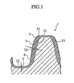
- FIG. 1 is a radial cross-sectional view of a part of the gear showing an embodiment of the sintered gear according to the present invention.
- a densified layer 11 is formed on the surface of a tooth of a gear 1, and a boundary surface 12 dividing the densified layer 11 from an interior 13 of the gear is provided.
- a tooth surface 2, that is, a tooth face 3 and a tooth flank 4 is processed so that a thickness 21 of the densified layer 11 is 300 to 1,000 microns, and specifically 500 microns in this embodiment.
- a bottom land 5 is processed so that a thickness 22 of the densified layer 11 is 10 to 300 microns, and specifically 150 microns in this embodiment.
- the porosity of the gear interior 13 is 11 to 13 % and that of the densified layer 11 is 0 to 11 %.
- the densified layer 11 is formed so that the thickness does not change steeply and the boundary surface 12 is smoothly continued from the side of the tooth face 3 to the side of the bottom land 5. In other words, the boundary face of the densified layers of the tooth face 3 and the bottom land 5 is continued seamlessly and has no substantial level difference.
- FIGs. 2(a) and 2(b) are sectional views illustrating an example of a manufacturing process of the sintered gear shown in FIG. 1 .
- FIG. 2(a) shows a tooth profile 31 of a gear material M before form rolling
- FIG. 2(b) shows a tooth profile 32 of a gear 1a after form rolling.
- the tooth profile 32 after form rolling is represented by a dashed line and the difference between the tooth profiles after and before form rolling means a form rolling allowance.
- Porosity of the gear material before form rolling exceeds 10 %. After form rolling, porosity of a densified layer 11a in FIG. 2(b) becomes 10 % or less.
- the thickness of the densified layer 11a gradually changes from 21a to 22b and a boundary surface 12a of the densified layer 11a is continuous (that is, smooth and non-angular). In other words, the boundary surface has no level difference caused by steeply changing the thickness of the densified layer.
- FIGs. 3(a) and 3(b) are cross-sectional views showing the case where the gear of the same tooth profile 32 is manufactured by form rolling of a tooth material M' of a different tooth profile 31'.
- FIG. 3(a) shows the tooth profile 31' of the tooth material M' before form rolling
- FIG. 3(b) shows a gear 1b after form rolling.
- the difference between the tooth profile 32 after form rolling and the tooth profile 31' before form rolling as shown in FIG. 3(a) means a form rolling allowance.
- the thickness of a densified layer 11b steeply changes also in the gear 1b after form rolling from 21b to 22b, and a level difference is made in the boundary surface 12b at a junction B between the densified layer 21b of the tooth surface and the densified layer 22b of the bottom land.
- the stress applied on the densified layer at the time of rolling contact concentrates to the level difference portion of the junction B, and the boundary surface between the level difference portion and its inner portion is likely to be damaged.
- the vibration generating on the tooth surface by rolling contact propagates through the densified layer 11b
- the vibration reflects on the boundary surface 12b at the level difference portion of the junction B and the ratio of the vibration propagating up to the densified layer of the bottom land is reduced due to a sudden narrowing in the vicinity of the level difference.
- vibratory wave energy concentrates into the vicinity of the level difference.
- a sintered gear having good strength and noise reduction characteristics is possibly obtained. Therefore, it is possible to effectively utilize a sintered gear having an overall density of about 6.7 to 7.1 g/cm 3 , taking advantage of lightness in weight as a merit of sintered alloy.
- a graphite powder was added to a ferroalloy powder having a composition by mass ratio of Fe-0.5%Ni-0.5%Mo (grain size: 80 mesh) to prepare a mixed powder (composition: Fe-0.5%Ni-0.5%Mo-0.3%C) in which the ratio of the graphite powder was 0.3 percent by mass.
- the following operation was performed using this mixed powder as a raw material powder.
- the raw material powder was pressed and compressed to form in a shape of a sprocket wheel. And it was sintered at 1,195 degrees C to obtain a gear material.
- This gear material was subjected to a form rolling process and then heated at 900 degrees C to obtain a sintered gear as Sample 1A having a densified layer as shown in FIG. 1 on the surface thereof.
- a form rolling allowance in the form rolling process was set to be 0.09 mm on the tooth surface and 0.02 mm on the bottom land and the tooth crest, and a form rolling pressure was set to be 3 ton.
- the raw material powder was formed in the same shape of a sprocket wheel as Sample 1A, by warm pressing, and sintered at 1,195 degrees C to obtain a gear material. This gear material was heated at 900 degrees C to obtain a sintered gear of Sample 1B.
- Example 2 The same raw material powder as in Example 1 was subjected to the pressing, sintering, form rolling and heating processes according to the same method as that used for Sample 1A, excepting that the form rolling allowance in form rolling process was changed case by case in the range of 0.02 to 0.12 mm, to manufacture sintered gears (of Samples 2A to 2F) each having a densified layer of the thickness shown in Table 2 over the tooth surface, bottom land and tooth crest.
- a sintered gear of Sample 2B' was manufactured by performing the pressing, sintering, form rolling and heating processes according to the same method as that used for Sample 2B, excepting that the shape of the sprocket of the formed compact had depression at its tooth flank as shown in FIG. 3 .
- Each of the sintered gears of Samples 2A to 2F and 2B' was subjected to a three-ball type pitching test to measure a bearing fatigue strength of the tooth surface. Moreover, a jig was contacted against the tooth face of the gear, and a load in the circumferential direction of the gear was applied repeatedly at 30 Hz until the tooth flank was broken, to determine the number of repetition when the tooth flank was broken. Based on the relationship between the load and the number of repetition at the time of breakage, a maximum load at which the tooth flank was not broken by the application of load of 10 7 times was then determined, thereby flexural fatigue strength of tooth flank was measured.
- Table 2 Sintered Gear Thickness of Densified Layer ( ⁇ m) Bearing Fatigue Strength (Mpa) Flexural Fatigue Strength of Tooth Flank (Mpa) Sample 2A 100 2800 330 Sample 2B 300 3400 333 Sample 2C 500 3450 335 Sample 2D 750 3500 339 Sample 2E 1000 3550 341 Sample 2F 1500 3550 341 Sample 2B' 300 3400 290
- Example 1 The same raw material powder as in Example 1 was subjected to pressing, sintering, form rolling and heating processes according to the same method as that used for Sample 1A, excepting that the form rolling allowance in form rolling process was changed case by case in the range of 0 to 0.06 mm, to manufacture sintered gears (of Samples 3A to 3F) each having a densified layer of the thickness shown in Table 3 over the bottom land.
- a sintered gear having good strength and noise reduction characteristics during driving operation can be achieved, using an inexpensive powder composed of Fe-Cu-C alloy or Fe-Ni-Mo-C alloy, and there is no need to adopt a raw material powder having a quality of special high grade. Accordingly, applicability of the sintered gear expands, and it can be utilized as means of reducing weight of devices equipped with a gear, cutting manufacturing costs and reducing noise.
Landscapes
- Engineering & Computer Science (AREA)
- Manufacturing & Machinery (AREA)
- Mechanical Engineering (AREA)
- Gears, Cams (AREA)
- Powder Metallurgy (AREA)
Claims (7)
- Gesintertes Zahnrad (1) bestehend aus einer gesinterten Legierung, die eine Metallmatrix und Poren aufweist, umfassend:eine erste verdichtete Schicht (11), die an einer Zahnoberfläche (2) mit einer Dicke (21) von 300 bis 1000 Mikrometer und einer Porosität von 10% oder weniger ausgebildet ist; undeine zweite verdichtete Schicht (11), die an einer Bodenfläche mit einer Dicke (22) von 10 bis 300 Mikrometer und einer Porosität von 10% oder weniger ausgebildet ist, bei dem eine Grenze (12) der ersten verdichteten Schicht mit einer Grenze (12) der zweiten verdichteten Schicht (11) ohne einen wesentlichen Niveauunterschied fortlaufend ist, bei dem der Porositätsunterschied zwischen einem inneren Kernabschnitt (13) des gesinterten Zahnrads und einer äußersten Oberfläche von sowohl der ersten verdichteten Schicht, als auch der zweiten verdichteten Schicht jeweils 7% oder größer in Bezug auf das Volumen ist.
- Gesintertes Zahnrad nach Anspruch 1, ferner umfassend:eine dritte verdichtete Schicht, die an einem Zahnkopf mit einer Dicke von 10 bis 300 Mikrometer ausgebildet ist und die Porosität von der gesinterten Legierung auf 10 % oder weniger reduziert ist, bei dem die Grenze der ersten verdichteten Schicht mit der Grenze der dritten verdichteten Schicht ohne einen wesentlichen Niveauunterschied fortlaufend ist.
- Gesintertes Zahnrad nach Anspruch 1, bei dem die Legierung ein Fe-Cu-C Legierung oder eine Fe-Ni-Mo-C Legierung ist.
- Gesintertes Zahnrad nach Anspruch 1, bei dem die gesinterte Legierung eine Zusammensetzung aus Fe - 0,5% Ni - 0,5% Mo - 0,3% C in Bezug auf die Masse aufweist.
- Gesintertes Zahnrad nach Anspruch 1, das eine allgemeine Dichte von 6,7 bis 7,1 g/cm3 aufweist.
- Verwendung des gesinterten Zahnrads nach Anspruch 1 für die Leistungsübertragung durch konvexe Zähne, die miteinander eingreifen.
- Verwendung des gesinterten Zahnrads nach Anspruch 1 als Kettenrad für die Leistungsübertragung an eine Kette.
Applications Claiming Priority (3)
| Application Number | Priority Date | Filing Date | Title |
|---|---|---|---|
| JP2002292287A JP2005344126A (ja) | 2002-10-04 | 2002-10-04 | 焼結歯車 |
| JP2002292287 | 2002-10-04 | ||
| PCT/JP2003/012723 WO2004030852A1 (ja) | 2002-10-04 | 2003-10-03 | 焼結歯車 |
Publications (3)
| Publication Number | Publication Date |
|---|---|
| EP1552895A1 EP1552895A1 (de) | 2005-07-13 |
| EP1552895A4 EP1552895A4 (de) | 2007-04-04 |
| EP1552895B1 true EP1552895B1 (de) | 2009-12-16 |
Family
ID=32063916
Family Applications (1)
| Application Number | Title | Priority Date | Filing Date |
|---|---|---|---|
| EP03751328A Expired - Lifetime EP1552895B1 (de) | 2002-10-04 | 2003-10-03 | Gesintertes getriebe |
Country Status (6)
| Country | Link |
|---|---|
| US (1) | US7556864B2 (de) |
| EP (1) | EP1552895B1 (de) |
| JP (2) | JP2005344126A (de) |
| CN (1) | CN1323785C (de) |
| DE (1) | DE60330585D1 (de) |
| WO (1) | WO2004030852A1 (de) |
Cited By (2)
| Publication number | Priority date | Publication date | Assignee | Title |
|---|---|---|---|---|
| DE102015201873A1 (de) | 2015-02-03 | 2016-08-18 | Gkn Sinter Metals Engineering Gmbh | Leises Zahnrad |
| DE102016103051A1 (de) | 2016-02-22 | 2017-08-24 | Gkn Sinter Metals Engineering Gmbh | Pumpenanordnung |
Families Citing this family (26)
| Publication number | Priority date | Publication date | Assignee | Title |
|---|---|---|---|---|
| JP2006233771A (ja) * | 2005-02-22 | 2006-09-07 | Mitsubishi Materials Pmg Corp | ポンプロータ |
| DE102005027137A1 (de) * | 2005-06-10 | 2006-12-14 | Gkn Sinter Metals Gmbh | Verzahnung aus Sintermaterial |
| DE102005027048A1 (de) * | 2005-06-10 | 2006-12-14 | Gkn Sinter Metals Gmbh | Gesintertes Verzahnungselement mit lokal-selektiver Oberflächenverdichtung |
| DE102005027142A1 (de) * | 2005-06-10 | 2006-12-14 | Gkn Sinter Metals Gmbh | Vorformgeometrie einer Verzahnung |
| DE102005027144A1 (de) * | 2005-06-10 | 2006-12-14 | Gkn Sinter Metals Gmbh | Oberflächenverdichtung einer Verzahnung |
| DE102005027050B4 (de) * | 2005-06-10 | 2021-12-30 | Gkn Sinter Metals Gmbh | Kraftfahrzeugbauteil mit Verzahnung |
| DE102005027054A1 (de) * | 2005-06-10 | 2006-12-28 | Gkn Sinter Metals Gmbh | Werkstück mit unterschiedlicher Beschaffenheit |
| DE102005027049A1 (de) * | 2005-06-10 | 2006-12-14 | Gkn Sinter Metals Gmbh | Belastbare Verzahnung |
| JP4804227B2 (ja) * | 2006-05-26 | 2011-11-02 | 日立粉末冶金株式会社 | 軸受複合歯車の製造方法 |
| US7722803B2 (en) * | 2006-07-27 | 2010-05-25 | Pmg Indiana Corp. | High carbon surface densified sintered steel products and method of production therefor |
| JP4618806B2 (ja) * | 2006-07-31 | 2011-01-26 | 株式会社エンプラス | 歯車 |
| AT505150B1 (de) * | 2006-10-24 | 2008-11-15 | Miba Sinter Austria Gmbh | Mehrfachrad |
| AT10838U1 (de) * | 2008-01-16 | 2009-11-15 | Miba Sinter Austria Gmbh | Sinterzahnrad |
| JP5276491B2 (ja) * | 2009-03-25 | 2013-08-28 | 住友電気工業株式会社 | 焼結体の表面緻密化方法 |
| AT508260B1 (de) * | 2009-05-20 | 2010-12-15 | Miba Sinter Austria Gmbh | Zahnrad |
| JP5485646B2 (ja) * | 2009-10-14 | 2014-05-07 | ポーライト株式会社 | 非含油性焼結歯車体 |
| AT509456B1 (de) * | 2010-08-31 | 2011-09-15 | Miba Sinter Austria Gmbh | Gesintertes zahnrad |
| AT510697B1 (de) | 2011-05-11 | 2012-06-15 | High Tech Coatings Gmbh | Bauteil mit einer adaptiven beschichtung |
| AT510282B1 (de) | 2011-05-11 | 2012-03-15 | High Tech Coatings Gmbh | Bauteil mit einer adaptiven beschichtung |
| CN102563009A (zh) * | 2012-02-06 | 2012-07-11 | 刘立文 | 一种防爆齿轮 |
| JP6226773B2 (ja) * | 2014-02-24 | 2017-11-08 | 株式会社椿本チエイン | スプロケット |
| US9599208B2 (en) * | 2015-02-12 | 2017-03-21 | Sram, Llc | Chainrings and crank assemblies |
| JP2020041191A (ja) * | 2018-09-11 | 2020-03-19 | トヨタ自動車株式会社 | 歯車の製造方法 |
| JP7299476B2 (ja) * | 2019-03-25 | 2023-06-28 | 株式会社椿本チエイン | スプロケット及び伝動機構 |
| JP7124230B2 (ja) * | 2019-08-30 | 2022-08-23 | 住友電気工業株式会社 | 焼結歯車、及び焼結歯車の製造方法 |
| EP4620624A3 (de) | 2022-06-16 | 2026-01-21 | Milwaukee Electric Tool Corporation | Kompaktes schlagwerkzeug |
Family Cites Families (9)
| Publication number | Priority date | Publication date | Assignee | Title |
|---|---|---|---|---|
| US5711187A (en) * | 1990-10-08 | 1998-01-27 | Formflo Ltd. | Gear wheels rolled from powder metal blanks and method of manufacture |
| CN2111154U (zh) * | 1991-12-12 | 1992-07-29 | 国营857厂 | 粉末冶金齿轮毛坯 |
| DE4211319C2 (de) * | 1992-04-04 | 1995-06-08 | Plansee Metallwerk | Verfahren zur Herstellung von Sintereisen-Formteilen mit porenfreier Zone |
| JP2000239710A (ja) | 1999-02-19 | 2000-09-05 | Tsubakimoto Chain Co | 焼結部品 |
| GB2360825B (en) * | 2000-03-30 | 2004-11-17 | Formflo Ltd | Gear wheels roll formed from powder metal blanks |
| SE0002448D0 (sv) * | 2000-06-28 | 2000-06-28 | Hoeganaes Ab | method of producig powder metal components |
| JP3698409B2 (ja) * | 2000-10-25 | 2005-09-21 | 本田技研工業株式会社 | 焼結スプロケット |
| US6517772B1 (en) * | 2001-09-26 | 2003-02-11 | Federal-Mogul World Wide, Inc. | Apparatus and method for forming powder metal gears |
| JP4166041B2 (ja) * | 2002-06-03 | 2008-10-15 | 株式会社椿本チエイン | 焼結スプロケット及びその製造方法 |
-
2002
- 2002-10-04 JP JP2002292287A patent/JP2005344126A/ja active Pending
-
2003
- 2003-10-03 US US10/529,866 patent/US7556864B2/en not_active Expired - Lifetime
- 2003-10-03 WO PCT/JP2003/012723 patent/WO2004030852A1/ja not_active Ceased
- 2003-10-03 DE DE60330585T patent/DE60330585D1/de not_active Expired - Lifetime
- 2003-10-03 JP JP2004541288A patent/JP4160561B2/ja not_active Expired - Lifetime
- 2003-10-03 EP EP03751328A patent/EP1552895B1/de not_active Expired - Lifetime
- 2003-10-03 CN CNB2003801008833A patent/CN1323785C/zh not_active Expired - Lifetime
Non-Patent Citations (1)
| Title |
|---|
| "Parallel-Axis Gear Terminology", AERO GEAR, INC, article "ANSI/AGMA Standard 1012-F90, Gear Nomenclature, Definitions with Terms and Symbols" * |
Cited By (3)
| Publication number | Priority date | Publication date | Assignee | Title |
|---|---|---|---|---|
| DE102015201873A1 (de) | 2015-02-03 | 2016-08-18 | Gkn Sinter Metals Engineering Gmbh | Leises Zahnrad |
| US10890241B2 (en) | 2015-02-03 | 2021-01-12 | Gkn Sinter Metals Engineering Gmbh | Quiet gear wheel and method for producing such a gear wheel |
| DE102016103051A1 (de) | 2016-02-22 | 2017-08-24 | Gkn Sinter Metals Engineering Gmbh | Pumpenanordnung |
Also Published As
| Publication number | Publication date |
|---|---|
| DE60330585D1 (de) | 2010-01-28 |
| EP1552895A1 (de) | 2005-07-13 |
| CN1323785C (zh) | 2007-07-04 |
| EP1552895A4 (de) | 2007-04-04 |
| JPWO2004030852A1 (ja) | 2006-02-02 |
| WO2004030852A1 (ja) | 2004-04-15 |
| CN1703292A (zh) | 2005-11-30 |
| US20050272545A1 (en) | 2005-12-08 |
| JP2005344126A (ja) | 2005-12-15 |
| JP4160561B2 (ja) | 2008-10-01 |
| US7556864B2 (en) | 2009-07-07 |
Similar Documents
| Publication | Publication Date | Title |
|---|---|---|
| US7556864B2 (en) | Sintered gear | |
| CA2121923C (en) | Gear making process | |
| US4059879A (en) | Method for the controlled mechanical working of sintered porous powder metal shapes to effect surface and subsurface densification | |
| US8337747B2 (en) | Process for manufacturing composite sintered machine components | |
| KR100311989B1 (ko) | 내치기어 | |
| EP2826577A1 (de) | Mechanische strukturkomponente, gesintertes getriebe und verfahren zur herstellung davon | |
| TW200526343A (en) | Method of flow forming a metal part | |
| KR20010052876A (ko) | 금속질 가루 성형 소재와 그 재압축 성형체 및 이 재압축성형체로부터 얻어지는 소결체 및 그들의 제조 방법 | |
| JP2007262536A (ja) | 焼結歯車およびその製造方法 | |
| JPS61129241A (ja) | プ−リ−の製造方法 | |
| WO2002034957A1 (en) | Sintered sprocket | |
| US6223437B1 (en) | Method for fabricating a friction bearing, and friction bearing | |
| JP2026011301A (ja) | 焼結歯車及びその製造方法 | |
| JP2520982Y2 (ja) | 歯付焼結プーリ | |
| JP2026011298A (ja) | 焼結歯車 | |
| KR20190126448A (ko) | 침탄 담금질재의 제조 방법 | |
| TW200534942A (en) | Method for the manufacturing of sintered metal parts | |
| Sigl et al. | Evolution of gear quality in helical P/M gears during processing | |
| US20240261881A1 (en) | Method for producing a component with a toothing | |
| Engström et al. | Surface densification and warm compaction lead to greater density in PM gears, resulting in higher strength and improved fatigue properties | |
| JPH06297143A (ja) | 浸炭鋼を用いた部材の製造方法 | |
| JP2015034610A (ja) | トルクコンバータ用ステータユニット | |
| JP2000034507A (ja) | 焼結転造歯車の製造方法 | |
| JPH09141374A (ja) | 転造歯車の製造方法 | |
| JPH1161204A (ja) | 摺動用メタルおよびその製造方法 |
Legal Events
| Date | Code | Title | Description |
|---|---|---|---|
| PUAI | Public reference made under article 153(3) epc to a published international application that has entered the european phase |
Free format text: ORIGINAL CODE: 0009012 |
|
| 17P | Request for examination filed |
Effective date: 20050426 |
|
| AK | Designated contracting states |
Kind code of ref document: A1 Designated state(s): AT BE BG CH CY CZ DE DK EE ES FI FR GB GR HU IE IT LI LU MC NL PT RO SE SI SK TR |
|
| RBV | Designated contracting states (corrected) |
Designated state(s): DE GB |
|
| A4 | Supplementary search report drawn up and despatched |
Effective date: 20070306 |
|
| 17Q | First examination report despatched |
Effective date: 20070702 |
|
| GRAP | Despatch of communication of intention to grant a patent |
Free format text: ORIGINAL CODE: EPIDOSNIGR1 |
|
| GRAS | Grant fee paid |
Free format text: ORIGINAL CODE: EPIDOSNIGR3 |
|
| GRAA | (expected) grant |
Free format text: ORIGINAL CODE: 0009210 |
|
| AK | Designated contracting states |
Kind code of ref document: B1 Designated state(s): DE GB |
|
| REG | Reference to a national code |
Ref country code: GB Ref legal event code: FG4D |
|
| REF | Corresponds to: |
Ref document number: 60330585 Country of ref document: DE Date of ref document: 20100128 Kind code of ref document: P |
|
| RAP2 | Party data changed (patent owner data changed or rights of a patent transferred) |
Owner name: HONDA GIKEN KOGYO KABUSHIKI KAISHA Owner name: HITACHI POWDERED METALS CO., LTD. |
|
| PLBE | No opposition filed within time limit |
Free format text: ORIGINAL CODE: 0009261 |
|
| STAA | Information on the status of an ep patent application or granted ep patent |
Free format text: STATUS: NO OPPOSITION FILED WITHIN TIME LIMIT |
|
| 26N | No opposition filed |
Effective date: 20100917 |
|
| PGFP | Annual fee paid to national office [announced via postgrant information from national office to epo] |
Ref country code: GB Payment date: 20220901 Year of fee payment: 20 |
|
| PGFP | Annual fee paid to national office [announced via postgrant information from national office to epo] |
Ref country code: DE Payment date: 20220831 Year of fee payment: 20 |
|
| REG | Reference to a national code |
Ref country code: DE Ref legal event code: R071 Ref document number: 60330585 Country of ref document: DE |
|
| REG | Reference to a national code |
Ref country code: GB Ref legal event code: PE20 Expiry date: 20231002 |
|
| PG25 | Lapsed in a contracting state [announced via postgrant information from national office to epo] |
Ref country code: GB Free format text: LAPSE BECAUSE OF EXPIRATION OF PROTECTION Effective date: 20231002 |