EP1552903B1 - Bandschleifmaschine, vorzugsweise für die Kombination mit einem Vorsatzgerät für das Ausschleifen von Rohrenden - Google Patents
Bandschleifmaschine, vorzugsweise für die Kombination mit einem Vorsatzgerät für das Ausschleifen von Rohrenden Download PDFInfo
- Publication number
- EP1552903B1 EP1552903B1 EP04030981A EP04030981A EP1552903B1 EP 1552903 B1 EP1552903 B1 EP 1552903B1 EP 04030981 A EP04030981 A EP 04030981A EP 04030981 A EP04030981 A EP 04030981A EP 1552903 B1 EP1552903 B1 EP 1552903B1
- Authority
- EP
- European Patent Office
- Prior art keywords
- belt
- motor
- grinding machine
- grinding
- screw spindle
- Prior art date
- Legal status (The legal status is an assumption and is not a legal conclusion. Google has not performed a legal analysis and makes no representation as to the accuracy of the status listed.)
- Expired - Lifetime
Links
- 230000000295 complement effect Effects 0.000 claims description 2
- 239000002826 coolant Substances 0.000 description 3
- 229910052751 metal Inorganic materials 0.000 description 2
- 239000002184 metal Substances 0.000 description 2
- XLYOFNOQVPJJNP-UHFFFAOYSA-N water Substances O XLYOFNOQVPJJNP-UHFFFAOYSA-N 0.000 description 2
- 229910000831 Steel Inorganic materials 0.000 description 1
- 238000010276 construction Methods 0.000 description 1
- 230000008878 coupling Effects 0.000 description 1
- 238000010168 coupling process Methods 0.000 description 1
- 238000005859 coupling reaction Methods 0.000 description 1
- 230000001419 dependent effect Effects 0.000 description 1
- 238000006073 displacement reaction Methods 0.000 description 1
- 238000004519 manufacturing process Methods 0.000 description 1
- 150000002739 metals Chemical class 0.000 description 1
- 230000001105 regulatory effect Effects 0.000 description 1
- 230000000284 resting effect Effects 0.000 description 1
- 230000000717 retained effect Effects 0.000 description 1
- 229910001220 stainless steel Inorganic materials 0.000 description 1
- 239000010935 stainless steel Substances 0.000 description 1
- 239000010959 steel Substances 0.000 description 1
- 230000001960 triggered effect Effects 0.000 description 1
Images




Classifications
-
- B—PERFORMING OPERATIONS; TRANSPORTING
- B24—GRINDING; POLISHING
- B24B—MACHINES, DEVICES, OR PROCESSES FOR GRINDING OR POLISHING; DRESSING OR CONDITIONING OF ABRADING SURFACES; FEEDING OF GRINDING, POLISHING, OR LAPPING AGENTS
- B24B21/00—Machines or devices using grinding or polishing belts; Accessories therefor
- B24B21/18—Accessories
- B24B21/20—Accessories for controlling or adjusting the tracking or the tension of the grinding belt
-
- B—PERFORMING OPERATIONS; TRANSPORTING
- B24—GRINDING; POLISHING
- B24B—MACHINES, DEVICES, OR PROCESSES FOR GRINDING OR POLISHING; DRESSING OR CONDITIONING OF ABRADING SURFACES; FEEDING OF GRINDING, POLISHING, OR LAPPING AGENTS
- B24B9/00—Machines or devices designed for grinding edges or bevels on work or for removing burrs; Accessories therefor
- B24B9/007—Machines or devices designed for grinding edges or bevels on work or for removing burrs; Accessories therefor for end faces of tubes
Definitions
- the invention relates to a belt grinding machine, preferably for combination with an attachment for grinding pipe ends and the like.
- a multi-functional belt grinding machine can be provided, which is suitable for a variety of diameters to be ground at various angles.
- Such belt grinders are used for work in railing production, frame and pipe constructions, shop fittings and much more.
- FIG. 2 A plan view of the belt grinding machine of the prior art is there in FIG. 2 shown.
- the sanding belt 2 is guided over a rear, connected to the motor 10 guide roller 5 and a front guide roller 4.
- the tension of the sanding belt 2 is held by means of a spring 9, which is designed as a spiral spring or spiral spring and lies outside of the tape run.
- the DE 295 04 077 U1 discloses a belt sander in which the distance between a rear drive roller and a diverting pulley is adjustable, the adjustability being achieved by adjusting the front part carrying the diverting pulley by a sprung tensioning device.
- the sprung tensioning device is arranged within the strip run.
- the DE 42 26 708 A1 relates to a belt sander which is controlled by a robot and whose programming is the movement of the workpiece.
- a contact roller is loaded by a pneumatic cylinder in the direction of the workpiece.
- the grinding belt is guided around four axially parallel rollers for contact, drive, deflection and clamping.
- a belt sander according to claim 1.
- Advantageous embodiments are the subject of the dependent claims. According to the invention it is provided that at a Belt grinder, which is preferably to be used in combination with a header for grinding pipe ends and the like, but also for other applications, a number of contact rollers with different diameter is provided around which the endlessly running abrasive belt is optionally placed, and that a device is provided for adjusting the belt tension within the belt run, which mechanically optimizes the belt tension of the sanding belt independently of the diameter of the contact roller.
- This has a gas spring, one end of which is retained and the second end is displaceably guided in one of at least two formed in the housing of the belt grinding and longitudinally extending slots and is pivotally mounted on a flat plate, wherein the sheet in at least two the slots is mounted and the motor flange is placed on the flat sheet metal.
- the belt sander may include a side regulating device having a threaded spindle eccentric to the motor rotation axis, operable from outside the belt grinder housing and disposed on a tab attached to the engine flange.
- This threaded spindle can easily tilt the motor with its flange in a rear position for adjusting the laterally correct tape running and the tape tension by exerting pressure on the cover plate.
- the adjustment is done by train in the direction of the cover plate or in the opposite direction. Both adjustment options complement each other because of the eccentricity.
- Essential to the invention is that a loading force is generated, which ensures the optimum tension of the abrasive belt.
- the coolant can be water.
- the housing of the belt sander and that of the attachment are preferably mechanically fixed to each other, for example by a connection by means of screws.
- FIG. 1 shows a belt sander 100, which is basically suitable for industrial indoor use in humid environments and is used for grinding, for example, steel, stainless steel and metals.
- a sanding belt is how better in FIG. 2 can be seen, powered by a motor 102.
- the respective resting abrasive belt can be laterally adjusted by means of an adjustment 104.
- the clamping and releasing of the respective sanding belt takes place via a lever mechanism 106.
- the motor 102 drives a drive pulley 108 around which the sanding belt (not visible in the drawing) is guided along a horizontal sanding table 110, which can be raised or lowered if necessary. and around a contact disk 112 back to the drive pulley 108th
- This per se known belt grinding machine is operated according to the invention with an attachment 200, which is fixed by means of a mechanical fixing device 224, preferably a simple screw connection to the belt grinding machine 100.
- the longer sanding belt is then guided accordingly to the attachment 200 and adjusted there and fixed, as will be explained in more detail below.
- the contact roller 206 can be adjusted by means of the height adjustment 202.
- An integrated spark box 204 is provided, which is filled with coolant, for example water, which absorbs the sparks generated during grinding.
- FIG. 3 shows a detailed view of the header 200.
- the contact roller 206 can be triggered and replaced by the release of the mechanical latch 208.
- a corresponding fixation ensures their secure fit.
- the side shift is via a cross slide actuated by the rotary lever 212, are operated.
- the feed is determined by the adjusting lever 214.
- the lever mechanism 216, 218 allows the adjustment of the center height of the contact roller 206.
- a vice 220 is provided to clamp the workpiece.
- a mechanism 222 is used to adjust the angles, with a large fissure of 10 ° and a small fissure of 5 °. Basically, any nicks in the range of 30 ° to 90 ° in the steps mentioned or also freely chosen.
- the assembly of belt grinder and attachment is done by first the electrical voltage at the main switch is disconnected and eye protection and thumbscrews, as far as disturbing and existing disassembled. Also sanding pad with spark box must be dismantled.
- FIG. 4 shows that the belt grinder and the attachment are assembled by means of 4 bolts 224.
- the previous sanding belt can be removed and the desired contact roller can be used in a holder. Then the new sanding belt is inserted and tensioned.
- FIG. 5 shows the positions of the tilt settings 226 that must be set in the first setup.
- FIG. 6 shows details of the mechanism for adjusting the tension of the abrasive belt in the belt grinding machine according to the present invention.
- a gas spring 130 is provided, one end 132 of which is fixed while the end 134 is slidably movable in a slot but fixedly mounted.
- FIG. 7 shows further details, for example, that under the drive pulley 108, a further slot 136 is provided which can serve for adjustment. Also several slots can be provided for guidance.
- FIG. 8 shows in sub-images (a), (b) and (c), as in spite of different diameters of contact rollers 206 and stationary contact disc 112 by displacing the drive pulley 108 (for example, in the in FIG. 7 shown slot 136), the same abrasive belt with optimized grinding voltage can be used. More specifically, the center distance between the contact roller 206 and the contact disk 112 is kept constant, while the drive pulley 108 can be moved accordingly. Once the position of the drive pulley 108 is fixed, the belt tension is optimized with a mechanism for adjusting the tension of the abrasive belt as described above.
Landscapes
- Engineering & Computer Science (AREA)
- Mechanical Engineering (AREA)
- Finish Polishing, Edge Sharpening, And Grinding By Specific Grinding Devices (AREA)
- Polishing Bodies And Polishing Tools (AREA)
- Grinding-Machine Dressing And Accessory Apparatuses (AREA)
Description
- Die Erfindung betrifft eine Bandschleifmaschine, vorzugsweise für die Kombination mit einem Vorsatzgerät für das Ausschleifen von Rohrenden und dergleichen. Mit der Erfindung kann eine multifunktionelle Bandschleifmaschine geschaffen werden, die für eine Vielzahl von zu schleifenden Durchmessern unter verschiedensten Winkeln geeignet ist. Solche Bandschleifmaschinen finden Einsatz für Arbeiten bei der Geländerfertigung, bei Rahmen- und Rohrkonstruktionen, Ladeneinrichtungen und vielem mehr.
- Bisher bekannt sind lediglich Komplettgeräte, die Motor, Schalter und andere teure Komponenten aufweisen. Eine solche Bandschleifmaschine ist aus der
DE 93 20 750 U1 bekannt. Eine Draufsicht auf die Bandschleifmaschine des Standes der Technik ist dort inFigur 2 gezeigt. Das Schleifband 2 wird dabei über eine hintere, mit dem Motor 10 verbundene Umlenkrolle 5 und eine vordere Umlenkrolle 4 geführt. Die Spannung des Schleifbandes 2 wird mittels einer Feder 9 gehalten, die als Spiralfeder bzw. Wendelfeder ausgebildet ist und außerhalb des Bandlaufes liegt. - Die
DE 295 04 077 U1 offenbart eine Bandschleifmaschine, bei der der Abstand zwischen einer hinteren Antriebsrolle und einer Umlenkrolle einstellbar ist, wobei die Verstellbarkeit dadurch erreicht wird, daß das Vorderteil, das die Umlenkrolle trägt, durch eine gefederte Spanneinrichtung justiert wird. Die gefederte Spanneinrichtung ist innerhalb des Bandlaufes angeordnet. - Die
DE 42 26 708 A1 betrifft eine Bandschleifmaschine, die von einem Roboter gesteuert wird und dessen Programmierung der Bewegung des Werkstückes. Dabei wird eine Kontaktrolle durch einen Pneumatikzylinder in Richtung des Werkstückes belastet. Das Schleifband wird um vier achsparallele Rollen für den Kontakt, den Antrieb, die Umlenkung und das Spannen geführt. - Es ist die Aufgabe der Erfindung, eine Bandschleifmaschine so zu gestalten, daß sie mit einer Anzahl von Kontaktrollen unterschiedlichen Durchmessers betrieben werden kann, wobei der Bandspannungsbereich entsprechend anzupassen ist.
- Diese Aufgabe wird durch ein Bandschleifgerät nach Anspruch 1 gelöst. Vorteilhafte Ausgestaltungen sind Gegenstand der Unteransprüche. Erfindungsgemäß ist vorgesehen, daß bei einer Bandschleifmaschine, die vorzugsweise in Kombination mit einem Vorsatzgerät für das Ausschleifen von Rohrenden und dergleichen, aber auch für andere Anwendungszwecke eingesetzt werden soll, eine Anzahl von Kontaktrollen mit unterschiedlichem Durchmesser zur Verfügung gestellt wird, um die das endlos laufende Schleifband wahlweise gelegt wird, und daß eine Einrichtung zum Anpassen der Bandspannung innerhalb des Bandlaufs vorgesehen ist, welche unabhängig vom Durchmesser der Kontaktrolle die Bandspannung des Schleifbandes mechanisch optimiert. Diese weist eine Gasfeder auf, deren eines Ende festgehalten ist und deren zweites Ende verschiebebeweglich in einem von mindestens zwei in dem Gehäuse der Bandschleifmaschine ausgebildeten und sich in Längsrichtung erstreckenden Langlöchern geführt ist und schwenkbar an einem flachen Blech montiert ist, wobei das Blech in mindestens zwei der Langlöcher angebracht ist und der Motorflansch auf das flache Blech aufgesetzt ist.
- Die Bandschleifmaschine kann eine Einrichtung für die Seitenregulierung mit einer zu der Motordrehachse exzentrischen Gewindespindel aufweisen, die von außerhalb des Gehäuses der Bandschleifmaschine betätigbar ist und auf einer an den Motorflansch angebrachten Lasche angeordnet ist.
- Diese Gewindespindel kann in einer hinteren Position zur Justierung des seitlich korrekten Bandlaufs und der Bandspannung durch Ausübung eines Drucks auf die Abdeckplatte den Motor mit seinem Flansch leicht kippen. In einer vorderen Position der Gewindespindel bei einer um 180° gedrehten Montage des Flansches mit dem Motor erfolgt die Justierung durch Zug in Richtung zur Abdeckplatte oder in Gegenrichtung. Beide Justiermöglichkeiten ergänzen sich dabei wegen der Exzentrizität.
- Wesentlich für die Erfindung ist, daß eine belastende Kraft erzeugt wird, die für die optimale Spannung des Schleifbandes sorgt.
- Dadurch, daß die Einrichtung zum Anpassen der Bandspannung in der Bandschleifmaschine vorgesehen ist, wird die Lage für die Antriebsscheibe des Schleifbandes entsprechend dem Durchmesser der Kontaktrolle geändert, während der Abstand zwischen Kontaktrolle und Kontaktscheibe konstant bleibt.
- Während des Schleifens entstehen Schleiffunken, die in einem vorzugsweise mit Kühlmittel befüllbaren Behälter aufgefangen werden. Das Kühlmittel kann Wasser sein.
- Das Gehäuse des Bandschleifgerätes und das des Vorsatzgerätes sind vorzugsweise mechanisch aneinander fixiert, beispielsweise durch eine Verbindung mittels Schrauben.
- Im folgenden soll die Erfindung lediglich beispielhaft anhand der beigefügten Zeichnung näher erläutert werden. Es zeigt:
- Figur 1
- eine Bandschleifmaschine, teilweise aufgerissen, mit einem Vorsatzgerät gemäß der vorliegenden Erfindung;
- Figur 2
- eine Bandschleifmaschine und ein Vorsatzgerät in entkoppelter Stellung;
- Figur 3
- eine Detailansicht des Vorsatzgerätes;
- Figur 4
- weitere bauliche Einzelheiten des Kopplungsmechanismus von Bandschleifmaschine und Vorsatzgerät;
- Figur 5
- eine perspektivische Darstellung von dem an die Bandschleifmaschine angekoppelten Vorsatzgerät;
- Figur 6
- eine Darstellung des Bandspannungsmechanismus;
- Figur 7
- weitere Einzelheiten des Bandspannungsmechanismus;
- Figur 8
- mit Teilbildern (a), (b) und (c) die Verlagerung der Antriebsscheibe entsprechend dem Durchmesser der Kontaktrolle.
- Figur 9
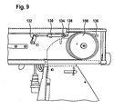
- Seitliche Ansicht der in einem Langloch verschiebbaren Gasfeder aus seitlichem Blickwinkel.
- Figur 10
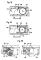
- Seitliche Ansicht der in einem Langloch verschiebbaren Gasfeder aus leicht nach hinten gedrehtem Blickwinkel.
- Figur 11
- Seitliche Ansicht der gespannten Gasfeder in vorderer Position des Langlochs.
- Figur 12
- Ansicht des flachen auf der Seite angebrachten Bleches in vier Langlöchern mit einer zur Gerätemitte hin angebrachten Stemschraube aus einem Blickwinkel von schräg hinten.
- Figur 13
- Ansicht des flachen auf der Seite angebrachten Bleches in vier Langlöchern mit einer zur Gerätemitte hin angebrachten Stemschraube aus einem Blickwinkel von schräg hinten.
- Figur 14
- Schematische Darstellungen des in zwei verschiedenen Anordnungen angebrachten Motors.
-
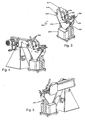
Figur 1 zeigt eine Bandschleifmaschine 100, die grundsätzlich zum industriellen Innengebrauch in feuchtfreien Umgebungen geeignet ist und zum Schleifen beispielsweise von Stahl, Edelstahl und Metallen eingesetzt wird. Ein Schleifband wird, wie besser inFigur 2 zu sehen ist, über einen Motor 102 angetrieben. Das jeweils aufliegende Schleifband kann dabei mittels einer Justierung 104 lateral eingerichtet werden. Das Spannen und Lösen des jeweiligen Schleifbandes erfolgt über einen Hebelmechanismus 106. Somit treibt der Motor 102 eine Antriebsscheibe 108, um die das - in der Zeichnung nicht sichtbare - Schleifband geführt ist, entlang eines waagerechten Schleiftisches 110, welcher gegebenenfalls angehoben oder abgesenkt werden kann, und um eine Kontaktscheibe 112 herum zurück zur Antriebsscheibe 108. - Diese an sich bekannte Bandschleifmaschine wird erfindungsgemäß mit einem Vorsatzgerät 200 betrieben, das mittels einer mechanischen Fixiereinrichtung 224, vorzugsweise einer einfachen Schraubenverbindung, an der Bandschleifmaschine 100 fixiert wird. Das längere Schleifband wird dann entsprechend bis zum Vorsatzgerät 200 geführt und dort justiert und fixiert, wie es im folgenden noch näher erläutert wird. Die Kontaktrolle 206 kann mittels der Höhenverstellung 202 angepaßt werden. Ein integrierter Funkenkasten 204 ist vorgesehen, der mit Kühlmittel, beispielsweise Wasser, gefüllt ist, welcher die beim Schleifen entstehenden Funken aufnimmt.
-
Figur 3 zeigt eine Detailansicht des Vorsatzgerätes 200. Die Kontaktrolle 206 kann über das Freigeben der mechanischen Verriegelung 208 ausgelöst und ausgetauscht werden. Eine entsprechende Fixierung sorgt für ihren sicheren Sitz. Mittels einer Stellschraube 210 kann der Tiefenanschlag des Werkstückes vorgegeben werden, die Seitenverschiebung wird über einen Querschlitten, betätigbar durch den Drehhebel 212, bedient werden. Der Vorschub wird durch den Stellhebel 214 bestimmt. Das Hebelwerk 216, 218 ermöglicht die Justierung der Mittenhöhe der Kontaktrolle 206. Schließlich ist ein Schraubstock 220 vorgesehen, um das Werkstück festzuspannen. Eine Mechanik 222 dient zur Einstellung der Winkel, mit einer großen Scharte von 10° und einer kleinen Scharte von 5°. Grundsätzlich können beliebige Scharten im Bereich von 30° bis zu 90° in den genannten Schritten oder auch frei gewählt eingestellt werden. - Der Zusammenbau von Bandschleifmaschine und Vorsatzgerät erfolgt, indem zunächst die elektrische Spannung beim Hauptschalter getrennt wird und Augenschutz und Rändelschrauben, soweit störend und vorhanden, demontiert werden. Auch Schleifauflage mit Funkenkasten müssen demontiert werden.
-
Figur 4 zeigt, daß die Bandschleifmaschine und das Vorsatzgerät mittels 4 Bolzen 224 zusammengebaut werden. Das bisherige Schleifband kann abgenommen werden und die gewünschte Kontaktrolle in eine Halterung eingesetzt werden. Dann wird das neue Schleifband eingelegt und gespannt. -
Figur 5 zeigt die Positionen der Kippeinstellungen 226, die bei der ersten Aufstellung eingestellt werden müssen. -
Figur 6 zeigt Einzelheiten des Mechanismus zum Einstellen der Spannung des Schleifbandes bei der Bandschleifmaschine gemäß der vorliegenden Erfindung. Eine Gasfeder 130 ist vorgesehen, deren eines Ende 132 festgelegt ist, während das Ende 134 in einem Langloch verschiebebeweglich, jedoch fest montierbar angeordnet ist. -
Figur 7 zeigt weitere Einzelheiten, beispielsweise, daß unter der Antriebsscheibe 108 ein weiteres Langloch 136 vorgesehen ist, das zur Justierung dienen kann. Auch mehrere Langlöcher können zur Führung vorgesehen sein. -
Figur 8 zeigt in Teilbildern (a), (b) und (c), wie trotz unterschiedlicher Durchmesser von Kontaktrollen 206 und feststehender Kontaktscheibe 112 durch Verlagern der Antriebsscheibe 108 (beispielsweise in dem inFigur 7 gezeigten Langloch 136) das gleiche Schleifband mit optimierter Schleifspannung verwendet werden kann. Genauer gesagt wird der Mittenabstand zwischen der Kontaktrolle 206 und der Kontaktscheibe 112 konstant gehalten, während sich die Antriebsscheibe 108 entsprechend verschieben läßt. Wenn einmal die Position der Antriebsscheibe 108 festgelegt ist, wird die Bandspannung mit einem Mechanismus zum Einstellen der Spannung des Schleifbandes, wie zuvor beschrieben, optimiert.
Claims (5)
- Bandschleifmaschine (100), vorzugsweise für die Kombination mit einem Vorsatzgerät (200) für das Ausschleifen von Rohrenden und dergleichen, bei der eine Anzahl von Kontaktrollen (206) mit unterschiedlichem Durchmesser zur Verfügung gestellt wird, um die das endlos laufende Schleifband wahlweise gelegt ist, wobei ein einen Motorflansch (116) aufweisender Motor (102) eine Antriebsscheibe (108) antreibt und innerhalb des Bandlaufs eine Einrichtung zum Anpassen der Bandspannung vorgesehen ist, welche unabhängig vom Durchmesser der Kontaktrolle (206) die Bandspannung des Schleifbandes mechanisch optimiert, dadurch gekennzeichnet, daß die Einrichtung zum Anpassen der Bandspannung eine Gasfeder (130) aufweist, deren eines Ende (132) festgehalten ist und deren zweites Ende (134) verschiebebeweglich in einem von mindestens zwei in dem Gehäuse der Bandschleifmaschine ausgebildeten sich in Längsrichtung erstreckenden Langlöchern (136) geführt ist und schwenkbar an einem flachen Blech montiert ist und wobei das Blech in mindestens zwei der Langlöcher (136) angebracht ist und der Motorflansch (116) auf das flache Blech aufgesetzt ist.
- Bandschleifmaschine (100) nach Anspruch 1, dadurch gekennzeichnet, daß eine Einrichtung für die Seitenregulierung des Bandlaufs vorgesehen ist, die eine zu der Motordrehachse exzentrische Gewindespindel (104) aufweist, die von außerhalb des Gehäuses der Bandschleifmaschine betätigbar ist und auf einer an dem Motorflansch (116) angebrachten Lasche (114) angeordnet ist.
- Bandschleifmaschine (100) nach Anspruch 2, dadurch gekennzeichnet, daß die Gewindespindel als Stemschraube ausgebildet ist.
- Bandschleifmaschine (100) nach Anspruch 2 oder 3, dadurch gekennzeichnet, daß der Motorflansch (116) in zwei Positionen montierbar ist und sich die Gewindespindel (104) in einem Fall hinter dem Motor (102) befindet und im anderen Fall vor dem Motor (102) und damit sich gegenseitig ergänzende Möglichkeiten der Justierung ergeben.
- Bandschleifmaschine (100) nach Anspruch 4, dadurch gekennzeichnet, daß die Justierung mit der Gewindespindel (104) in ihrer Position hinter dem Motor (102) durch Ausüben eines Drucks auf eine Abdeckplatte realisiert ist, während die Justierung mit der Gewindespindel (104) in ihrer Position vor dem Motor (102) durch Zug der Abdeckplatte ermöglicht wird.
Priority Applications (1)
| Application Number | Priority Date | Filing Date | Title |
|---|---|---|---|
| PL04030981T PL1552903T3 (pl) | 2004-01-06 | 2004-12-29 | Szlifierka taśmowa do kombinacji z przystawką do szlifowania końcówek rur |
Applications Claiming Priority (2)
| Application Number | Priority Date | Filing Date | Title |
|---|---|---|---|
| DE202004000104U | 2004-01-06 | ||
| DE202004000104U DE202004000104U1 (de) | 2004-01-06 | 2004-01-06 | Bandschleifmaschine, vorzugsweise für die Kombination mit einem Vorsatzgerät für das Ausschleifen von Rohrenden |
Publications (3)
| Publication Number | Publication Date |
|---|---|
| EP1552903A2 EP1552903A2 (de) | 2005-07-13 |
| EP1552903A3 EP1552903A3 (de) | 2005-09-07 |
| EP1552903B1 true EP1552903B1 (de) | 2008-07-02 |
Family
ID=32240747
Family Applications (1)
| Application Number | Title | Priority Date | Filing Date |
|---|---|---|---|
| EP04030981A Expired - Lifetime EP1552903B1 (de) | 2004-01-06 | 2004-12-29 | Bandschleifmaschine, vorzugsweise für die Kombination mit einem Vorsatzgerät für das Ausschleifen von Rohrenden |
Country Status (8)
| Country | Link |
|---|---|
| US (1) | US20050221735A1 (de) |
| EP (1) | EP1552903B1 (de) |
| CN (1) | CN1663743B (de) |
| AT (1) | ATE399619T1 (de) |
| DE (2) | DE202004000104U1 (de) |
| DK (1) | DK1552903T3 (de) |
| ES (1) | ES2310699T3 (de) |
| PL (1) | PL1552903T3 (de) |
Families Citing this family (11)
| Publication number | Priority date | Publication date | Assignee | Title |
|---|---|---|---|---|
| EP1688216A1 (de) * | 2005-02-02 | 2006-08-09 | Multi-Tool A/S | Bandschleifmaschine, vorzugsweise für die Kombination mit einem Vorsatzgerät für das Ausschleifen von Rohrenden |
| DE102005063241B4 (de) * | 2005-12-20 | 2025-08-07 | C. & E. Fein Gmbh | Bandschleifmaschine mit Aufsatzmodul |
| DE102006007709B4 (de) * | 2006-02-14 | 2019-01-31 | C. & E. Fein Gmbh | Bandschleifmaschine |
| DE102006013436B4 (de) | 2006-03-14 | 2018-10-31 | C. & E. Fein Gmbh | Bandschleifmaschine zum Außenrundschleifen von Rohren |
| CN102990494B (zh) * | 2011-09-08 | 2015-05-13 | 莱州市鑫岳机械有限公司 | 小型多功能砂带机 |
| DE102013111807A1 (de) | 2013-10-25 | 2015-04-30 | C. & E. Fein Gmbh | Bandschleifmaschine mit miteinander koppelbaren Bandschleifmodulen |
| CN103962919B (zh) * | 2014-04-25 | 2017-06-20 | 陈美青 | 一种抛光机 |
| DE102015205624A1 (de) * | 2015-03-27 | 2016-09-29 | Siemens Aktiengesellschaft | Schleifmaschine sowie Verfahren zum Bearbeiten einer Anstreifkante einer Laufschaufel |
| CN105538101A (zh) * | 2015-12-05 | 2016-05-04 | 芜湖山野电器有限公司 | 一种抛光机 |
| CN105500155A (zh) * | 2015-12-05 | 2016-04-20 | 芜湖山野电器有限公司 | 一种抛光装置 |
| CN112518523A (zh) * | 2020-12-02 | 2021-03-19 | 汤武义 | 一种薄壁冲压件的自动抛磨系统 |
Family Cites Families (10)
| Publication number | Priority date | Publication date | Assignee | Title |
|---|---|---|---|---|
| US3429077A (en) * | 1966-04-15 | 1969-02-25 | Lyndon V Grover | Sander |
| US4221081A (en) * | 1978-08-28 | 1980-09-09 | Everett Charles T | Dust collector system for belt sander |
| CH686350A5 (de) * | 1992-02-07 | 1996-03-15 | Sig Schweiz Industrieges | Bandschleifmaschine. |
| DE9320750U1 (de) * | 1993-04-02 | 1995-01-05 | Almi Machinefabriek B.V., Vriezenveen | Vorrichtung zum endseitigen Ausformen von rohrförmigen Werkstücken mit unterschiedlichen Durchmessern |
| DE4310887B4 (de) * | 1993-04-02 | 2004-09-09 | Almi Machinefabriek Vriezenveen B.V. | Vorrichtung zum endseitigen Ausformen von rohrförmigen Werkstücken mit unterschiedlichen Durchmessern |
| DE29504077U1 (de) * | 1995-03-10 | 1995-04-27 | Multi-Tool A/S, Jelling | Bandschleifmaschine |
| US5830046A (en) * | 1996-10-28 | 1998-11-03 | Vulcan Engineering Co. | Belt shifting idler pulley for reciprocating an abrasive belt |
| DE29904027U1 (de) * | 1999-03-05 | 1999-05-27 | Multi-Tool A/S, Jelling | Schleifmaschine |
| TW485857U (en) * | 2001-04-12 | 2002-05-01 | Shang-Zhang Liu | Adjustment device for emery belt of emery belt machine |
| ITRM20010677A1 (it) * | 2001-11-15 | 2003-05-15 | New Tech Srl | Levigatrice per incavi di estremita' di pezzi tubolari utilizzabile per la generica smerigliatura. |
-
2004
- 2004-01-06 DE DE202004000104U patent/DE202004000104U1/de not_active Expired - Lifetime
- 2004-12-29 PL PL04030981T patent/PL1552903T3/pl unknown
- 2004-12-29 AT AT04030981T patent/ATE399619T1/de not_active IP Right Cessation
- 2004-12-29 ES ES04030981T patent/ES2310699T3/es not_active Expired - Lifetime
- 2004-12-29 EP EP04030981A patent/EP1552903B1/de not_active Expired - Lifetime
- 2004-12-29 DE DE502004007481T patent/DE502004007481D1/de not_active Expired - Lifetime
- 2004-12-29 DK DK04030981T patent/DK1552903T3/da active
-
2005
- 2005-01-06 US US11/029,398 patent/US20050221735A1/en not_active Abandoned
- 2005-01-06 CN CN2005100517697A patent/CN1663743B/zh not_active Expired - Fee Related
Also Published As
| Publication number | Publication date |
|---|---|
| DK1552903T3 (da) | 2008-11-03 |
| PL1552903T3 (pl) | 2008-12-31 |
| US20050221735A1 (en) | 2005-10-06 |
| EP1552903A2 (de) | 2005-07-13 |
| ATE399619T1 (de) | 2008-07-15 |
| DE202004000104U1 (de) | 2004-04-29 |
| CN1663743B (zh) | 2012-08-08 |
| CN1663743A (zh) | 2005-09-07 |
| EP1552903A3 (de) | 2005-09-07 |
| DE502004007481D1 (de) | 2008-08-14 |
| ES2310699T3 (es) | 2009-01-16 |
Similar Documents
| Publication | Publication Date | Title |
|---|---|---|
| EP0623421B1 (de) | Vorrichtung zum endseitigen Ausformen von rohrförmigen Werkstücken mit unterschiedlichen Durchmessern | |
| EP2916984B1 (de) | Vorrichtung zum halten einer fräs- und/oder schleifmaschine | |
| EP1700647B1 (de) | Biegevorrichtung für stab- und rohrförmige Werkstücke und Faltenglätteranordnung | |
| EP1552903A2 (de) | Bandschleifmaschine, vorzugsweise für die Kombination mit einem Vorsatzgerät für das Ausschleifen von Rohrenden | |
| DE2519190C3 (de) | Kopierschleifgerät zum maßgerechten Schleifen von Schaufelblättern für Turbinen und Verdichter | |
| EP1688216A1 (de) | Bandschleifmaschine, vorzugsweise für die Kombination mit einem Vorsatzgerät für das Ausschleifen von Rohrenden | |
| EP0904907B1 (de) | Seilsäge mit Seilspeicherrolle | |
| DE102006007709B4 (de) | Bandschleifmaschine | |
| AT398051B (de) | Laufdraht-schneidmaschine | |
| DE202014100072U1 (de) | Bandschleifmaschine | |
| DE29504077U1 (de) | Bandschleifmaschine | |
| DE973395C (de) | Anleimmaschine fuer Vorsatzblaetter eines Buchblocks mit Vorleimvorrichtung fuer die auf den Vorsatzblaettern liegenden Laengsraender des Gazestreifens des Buchrueckens | |
| DE3921711C1 (de) | ||
| EP4461463A1 (de) | Rundschleifmaschinenzubehör zum spitzenlosen schleifen auf einer rundschleifmaschine | |
| DE20212135U1 (de) | Abwickelvorrichtung für bandförmiges Material | |
| DE9320750U1 (de) | Vorrichtung zum endseitigen Ausformen von rohrförmigen Werkstücken mit unterschiedlichen Durchmessern | |
| DE19721792C2 (de) | Vorrichtung zum Halten und Nachstellen eines Honsteins | |
| DD271870A1 (de) | Waelzlagerschleifmaschine | |
| DE19704088A1 (de) | Handbandschleifer | |
| DE2358928B2 (de) | Einrichtung zum Läppen von Werkzeugstählen o.dgl. mit Hartmetalleinlagen | |
| DE2158191C3 (de) | Vorrichtung zum Entgraten von geraden Blechbändern | |
| DE4038446C2 (de) | ||
| DE202025104573U1 (de) | Vorrichtung zur Aufnahme eines Stahlhalbzeuges | |
| DE29810731U1 (de) | Biegerichtmaschine | |
| DE3624742A1 (de) | Einrichtung zum einlegen von faserband in eine spinnkanne |
Legal Events
| Date | Code | Title | Description |
|---|---|---|---|
| PUAI | Public reference made under article 153(3) epc to a published international application that has entered the european phase |
Free format text: ORIGINAL CODE: 0009012 |
|
| AK | Designated contracting states |
Kind code of ref document: A2 Designated state(s): AT BE BG CH CY CZ DE DK EE ES FI FR GB GR HU IE IS IT LI LT LU MC NL PL PT RO SE SI SK TR |
|
| AX | Request for extension of the european patent |
Extension state: AL BA HR LV MK YU |
|
| PUAL | Search report despatched |
Free format text: ORIGINAL CODE: 0009013 |
|
| AK | Designated contracting states |
Kind code of ref document: A3 Designated state(s): AT BE BG CH CY CZ DE DK EE ES FI FR GB GR HU IE IS IT LI LT LU MC NL PL PT RO SE SI SK TR |
|
| AX | Request for extension of the european patent |
Extension state: AL BA HR LV MK YU |
|
| 17P | Request for examination filed |
Effective date: 20060204 |
|
| AKX | Designation fees paid |
Designated state(s): AT BE BG CH CY CZ DE DK EE ES FI FR GB GR HU IE IS IT LI LT LU MC NL PL PT RO SE SI SK TR |
|
| 17Q | First examination report despatched |
Effective date: 20060711 |
|
| 17Q | First examination report despatched |
Effective date: 20060711 |
|
| GRAP | Despatch of communication of intention to grant a patent |
Free format text: ORIGINAL CODE: EPIDOSNIGR1 |
|
| GRAS | Grant fee paid |
Free format text: ORIGINAL CODE: EPIDOSNIGR3 |
|
| GRAA | (expected) grant |
Free format text: ORIGINAL CODE: 0009210 |
|
| AK | Designated contracting states |
Kind code of ref document: B1 Designated state(s): AT BE BG CH CY CZ DE DK EE ES FI FR GB GR HU IE IS IT LI LT LU MC NL PL PT RO SE SI SK TR |
|
| REG | Reference to a national code |
Ref country code: GB Ref legal event code: FG4D Free format text: NOT ENGLISH |
|
| REG | Reference to a national code |
Ref country code: CH Ref legal event code: EP |
|
| REF | Corresponds to: |
Ref document number: 502004007481 Country of ref document: DE Date of ref document: 20080814 Kind code of ref document: P |
|
| REG | Reference to a national code |
Ref country code: IE Ref legal event code: FG4D Free format text: LANGUAGE OF EP DOCUMENT: GERMAN |
|
| REG | Reference to a national code |
Ref country code: RO Ref legal event code: EPE |
|
| PG25 | Lapsed in a contracting state [announced via postgrant information from national office to epo] |
Ref country code: SI Free format text: LAPSE BECAUSE OF FAILURE TO SUBMIT A TRANSLATION OF THE DESCRIPTION OR TO PAY THE FEE WITHIN THE PRESCRIBED TIME-LIMIT Effective date: 20080702 |
|
| REG | Reference to a national code |
Ref country code: DK Ref legal event code: T3 |
|
| REG | Reference to a national code |
Ref country code: PL Ref legal event code: T3 |
|
| REG | Reference to a national code |
Ref country code: ES Ref legal event code: FG2A Ref document number: 2310699 Country of ref document: ES Kind code of ref document: T3 |
|
| PG25 | Lapsed in a contracting state [announced via postgrant information from national office to epo] |
Ref country code: LT Free format text: LAPSE BECAUSE OF FAILURE TO SUBMIT A TRANSLATION OF THE DESCRIPTION OR TO PAY THE FEE WITHIN THE PRESCRIBED TIME-LIMIT Effective date: 20080702 Ref country code: PT Free format text: LAPSE BECAUSE OF FAILURE TO SUBMIT A TRANSLATION OF THE DESCRIPTION OR TO PAY THE FEE WITHIN THE PRESCRIBED TIME-LIMIT Effective date: 20081202 Ref country code: IS Free format text: LAPSE BECAUSE OF FAILURE TO SUBMIT A TRANSLATION OF THE DESCRIPTION OR TO PAY THE FEE WITHIN THE PRESCRIBED TIME-LIMIT Effective date: 20081102 |
|
| REG | Reference to a national code |
Ref country code: IE Ref legal event code: FD4D |
|
| PG25 | Lapsed in a contracting state [announced via postgrant information from national office to epo] |
Ref country code: BG Free format text: LAPSE BECAUSE OF FAILURE TO SUBMIT A TRANSLATION OF THE DESCRIPTION OR TO PAY THE FEE WITHIN THE PRESCRIBED TIME-LIMIT Effective date: 20081002 Ref country code: FI Free format text: LAPSE BECAUSE OF FAILURE TO SUBMIT A TRANSLATION OF THE DESCRIPTION OR TO PAY THE FEE WITHIN THE PRESCRIBED TIME-LIMIT Effective date: 20080702 |
|
| REG | Reference to a national code |
Ref country code: HU Ref legal event code: AG4A Ref document number: E004418 Country of ref document: HU |
|
| PG25 | Lapsed in a contracting state [announced via postgrant information from national office to epo] |
Ref country code: IE Free format text: LAPSE BECAUSE OF FAILURE TO SUBMIT A TRANSLATION OF THE DESCRIPTION OR TO PAY THE FEE WITHIN THE PRESCRIBED TIME-LIMIT Effective date: 20080702 Ref country code: EE Free format text: LAPSE BECAUSE OF FAILURE TO SUBMIT A TRANSLATION OF THE DESCRIPTION OR TO PAY THE FEE WITHIN THE PRESCRIBED TIME-LIMIT Effective date: 20080702 |
|
| PLBE | No opposition filed within time limit |
Free format text: ORIGINAL CODE: 0009261 |
|
| STAA | Information on the status of an ep patent application or granted ep patent |
Free format text: STATUS: NO OPPOSITION FILED WITHIN TIME LIMIT |
|
| PG25 | Lapsed in a contracting state [announced via postgrant information from national office to epo] |
Ref country code: SK Free format text: LAPSE BECAUSE OF FAILURE TO SUBMIT A TRANSLATION OF THE DESCRIPTION OR TO PAY THE FEE WITHIN THE PRESCRIBED TIME-LIMIT Effective date: 20080702 |
|
| 26N | No opposition filed |
Effective date: 20090403 |
|
| BERE | Be: lapsed |
Owner name: MULTI-TOOL A/S Effective date: 20081231 |
|
| PG25 | Lapsed in a contracting state [announced via postgrant information from national office to epo] |
Ref country code: MC Free format text: LAPSE BECAUSE OF NON-PAYMENT OF DUE FEES Effective date: 20081231 |
|
| REG | Reference to a national code |
Ref country code: CH Ref legal event code: PL |
|
| PG25 | Lapsed in a contracting state [announced via postgrant information from national office to epo] |
Ref country code: BE Free format text: LAPSE BECAUSE OF NON-PAYMENT OF DUE FEES Effective date: 20081231 |
|
| PG25 | Lapsed in a contracting state [announced via postgrant information from national office to epo] |
Ref country code: CH Free format text: LAPSE BECAUSE OF NON-PAYMENT OF DUE FEES Effective date: 20081231 Ref country code: LI Free format text: LAPSE BECAUSE OF NON-PAYMENT OF DUE FEES Effective date: 20081231 |
|
| PG25 | Lapsed in a contracting state [announced via postgrant information from national office to epo] |
Ref country code: SE Free format text: LAPSE BECAUSE OF FAILURE TO SUBMIT A TRANSLATION OF THE DESCRIPTION OR TO PAY THE FEE WITHIN THE PRESCRIBED TIME-LIMIT Effective date: 20081002 |
|
| PG25 | Lapsed in a contracting state [announced via postgrant information from national office to epo] |
Ref country code: AT Free format text: LAPSE BECAUSE OF NON-PAYMENT OF DUE FEES Effective date: 20081229 |
|
| PG25 | Lapsed in a contracting state [announced via postgrant information from national office to epo] |
Ref country code: CY Free format text: LAPSE BECAUSE OF FAILURE TO SUBMIT A TRANSLATION OF THE DESCRIPTION OR TO PAY THE FEE WITHIN THE PRESCRIBED TIME-LIMIT Effective date: 20080702 Ref country code: LU Free format text: LAPSE BECAUSE OF NON-PAYMENT OF DUE FEES Effective date: 20081229 |
|
| PG25 | Lapsed in a contracting state [announced via postgrant information from national office to epo] |
Ref country code: TR Free format text: LAPSE BECAUSE OF FAILURE TO SUBMIT A TRANSLATION OF THE DESCRIPTION OR TO PAY THE FEE WITHIN THE PRESCRIBED TIME-LIMIT Effective date: 20080702 |
|
| PG25 | Lapsed in a contracting state [announced via postgrant information from national office to epo] |
Ref country code: GR Free format text: LAPSE BECAUSE OF FAILURE TO SUBMIT A TRANSLATION OF THE DESCRIPTION OR TO PAY THE FEE WITHIN THE PRESCRIBED TIME-LIMIT Effective date: 20081003 |
|
| PGFP | Annual fee paid to national office [announced via postgrant information from national office to epo] |
Ref country code: ES Payment date: 20141111 Year of fee payment: 11 Ref country code: CZ Payment date: 20141208 Year of fee payment: 11 Ref country code: RO Payment date: 20141117 Year of fee payment: 11 Ref country code: GB Payment date: 20141224 Year of fee payment: 11 |
|
| PGFP | Annual fee paid to national office [announced via postgrant information from national office to epo] |
Ref country code: HU Payment date: 20141125 Year of fee payment: 11 Ref country code: NL Payment date: 20141210 Year of fee payment: 11 |
|
| PGFP | Annual fee paid to national office [announced via postgrant information from national office to epo] |
Ref country code: IT Payment date: 20141203 Year of fee payment: 11 |
|
| REG | Reference to a national code |
Ref country code: FR Ref legal event code: PLFP Year of fee payment: 12 |
|
| PGFP | Annual fee paid to national office [announced via postgrant information from national office to epo] |
Ref country code: DK Payment date: 20151210 Year of fee payment: 12 |
|
| PGFP | Annual fee paid to national office [announced via postgrant information from national office to epo] |
Ref country code: FR Payment date: 20151110 Year of fee payment: 12 Ref country code: PL Payment date: 20151102 Year of fee payment: 12 |
|
| PG25 | Lapsed in a contracting state [announced via postgrant information from national office to epo] |
Ref country code: CZ Free format text: LAPSE BECAUSE OF NON-PAYMENT OF DUE FEES Effective date: 20151229 |
|
| GBPC | Gb: european patent ceased through non-payment of renewal fee |
Effective date: 20151229 |
|
| PG25 | Lapsed in a contracting state [announced via postgrant information from national office to epo] |
Ref country code: RO Free format text: LAPSE BECAUSE OF NON-PAYMENT OF DUE FEES Effective date: 20151229 |
|
| REG | Reference to a national code |
Ref country code: NL Ref legal event code: MM Effective date: 20160101 |
|
| PG25 | Lapsed in a contracting state [announced via postgrant information from national office to epo] |
Ref country code: GB Free format text: LAPSE BECAUSE OF NON-PAYMENT OF DUE FEES Effective date: 20151229 Ref country code: NL Free format text: LAPSE BECAUSE OF NON-PAYMENT OF DUE FEES Effective date: 20160101 Ref country code: HU Free format text: LAPSE BECAUSE OF NON-PAYMENT OF DUE FEES Effective date: 20151230 |
|
| PG25 | Lapsed in a contracting state [announced via postgrant information from national office to epo] |
Ref country code: IT Free format text: LAPSE BECAUSE OF NON-PAYMENT OF DUE FEES Effective date: 20151229 |
|
| REG | Reference to a national code |
Ref country code: ES Ref legal event code: FD2A Effective date: 20170126 |
|
| PG25 | Lapsed in a contracting state [announced via postgrant information from national office to epo] |
Ref country code: ES Free format text: LAPSE BECAUSE OF NON-PAYMENT OF DUE FEES Effective date: 20151230 |
|
| REG | Reference to a national code |
Ref country code: DK Ref legal event code: EBP Effective date: 20161231 |
|
| REG | Reference to a national code |
Ref country code: FR Ref legal event code: ST Effective date: 20170831 |
|
| PG25 | Lapsed in a contracting state [announced via postgrant information from national office to epo] |
Ref country code: FR Free format text: LAPSE BECAUSE OF NON-PAYMENT OF DUE FEES Effective date: 20170102 |
|
| PG25 | Lapsed in a contracting state [announced via postgrant information from national office to epo] |
Ref country code: DK Free format text: LAPSE BECAUSE OF NON-PAYMENT OF DUE FEES Effective date: 20161231 |
|
| PG25 | Lapsed in a contracting state [announced via postgrant information from national office to epo] |
Ref country code: PL Free format text: LAPSE BECAUSE OF NON-PAYMENT OF DUE FEES Effective date: 20161229 |
|
| REG | Reference to a national code |
Ref country code: DE Ref legal event code: R082 Ref document number: 502004007481 Country of ref document: DE Representative=s name: HENTRICH PATENTANWAELTE PARTG MBB, DE Ref country code: DE Ref legal event code: R081 Ref document number: 502004007481 Country of ref document: DE Owner name: C. & E. FEIN GMBH, DE Free format text: FORMER OWNER: MULTI-TOOL A/S, JELLING, DK |
|
| REG | Reference to a national code |
Ref country code: DE Ref legal event code: R082 Ref document number: 502004007481 Country of ref document: DE |
|
| PGFP | Annual fee paid to national office [announced via postgrant information from national office to epo] |
Ref country code: DE Payment date: 20231214 Year of fee payment: 20 |
|
| REG | Reference to a national code |
Ref country code: DE Ref legal event code: R071 Ref document number: 502004007481 Country of ref document: DE |