EP1552909A1 - Schreitbewegungsvorrichtung und schreitsteuervorrichtung dafür sowie schreitsteuerverfahren - Google Patents
Schreitbewegungsvorrichtung und schreitsteuervorrichtung dafür sowie schreitsteuerverfahren Download PDFInfo
- Publication number
- EP1552909A1 EP1552909A1 EP03736033A EP03736033A EP1552909A1 EP 1552909 A1 EP1552909 A1 EP 1552909A1 EP 03736033 A EP03736033 A EP 03736033A EP 03736033 A EP03736033 A EP 03736033A EP 1552909 A1 EP1552909 A1 EP 1552909A1
- Authority
- EP
- European Patent Office
- Prior art keywords
- force
- foot
- contact
- force sensor
- gait
- Prior art date
- Legal status (The legal status is an assumption and is not a legal conclusion. Google has not performed a legal analysis and makes no representation as to the accuracy of the status listed.)
- Withdrawn
Links
Images



Classifications
-
- B—PERFORMING OPERATIONS; TRANSPORTING
- B25—HAND TOOLS; PORTABLE POWER-DRIVEN TOOLS; MANIPULATORS
- B25J—MANIPULATORS; CHAMBERS PROVIDED WITH MANIPULATION DEVICES
- B25J13/00—Controls for manipulators
- B25J13/08—Controls for manipulators by means of sensing devices, e.g. viewing or touching devices
- B25J13/085—Force or torque sensors
-
- A—HUMAN NECESSITIES
- A63—SPORTS; GAMES; AMUSEMENTS
- A63H—TOYS, e.g. TOPS, DOLLS, HOOPS OR BUILDING BLOCKS
- A63H11/00—Self-movable toy figures
- A63H11/18—Figure toys which perform a realistic walking motion
-
- B—PERFORMING OPERATIONS; TRANSPORTING
- B25—HAND TOOLS; PORTABLE POWER-DRIVEN TOOLS; MANIPULATORS
- B25J—MANIPULATORS; CHAMBERS PROVIDED WITH MANIPULATION DEVICES
- B25J19/00—Accessories fitted to manipulators, e.g. for monitoring, for viewing; Safety devices combined with or specially adapted for use in connection with manipulators
- B25J19/02—Sensing devices
-
- B—PERFORMING OPERATIONS; TRANSPORTING
- B25—HAND TOOLS; PORTABLE POWER-DRIVEN TOOLS; MANIPULATORS
- B25J—MANIPULATORS; CHAMBERS PROVIDED WITH MANIPULATION DEVICES
- B25J9/00—Program-controlled manipulators
- B25J9/16—Program controls
- B25J9/1628—Program controls characterised by the control loop
- B25J9/1633—Program controls characterised by the control loop compliant, force, torque control, e.g. combined with position control
-
- B—PERFORMING OPERATIONS; TRANSPORTING
- B62—LAND VEHICLES FOR TRAVELLING OTHERWISE THAN ON RAILS
- B62D—MOTOR VEHICLES; TRAILERS
- B62D57/00—Vehicles characterised by having other propulsion or other ground- engaging means than wheels or endless track, alone or in addition to wheels or endless track
- B62D57/02—Vehicles characterised by having other propulsion or other ground- engaging means than wheels or endless track, alone or in addition to wheels or endless track with ground-engaging propulsion means, e.g. walking members
- B62D57/032—Vehicles characterised by having other propulsion or other ground- engaging means than wheels or endless track, alone or in addition to wheels or endless track with ground-engaging propulsion means, e.g. walking members with alternately or sequentially lifted supporting base and legs; with alternately or sequentially lifted feet or skid
-
- Y—GENERAL TAGGING OF NEW TECHNOLOGICAL DEVELOPMENTS; GENERAL TAGGING OF CROSS-SECTIONAL TECHNOLOGIES SPANNING OVER SEVERAL SECTIONS OF THE IPC; TECHNICAL SUBJECTS COVERED BY FORMER USPC CROSS-REFERENCE ART COLLECTIONS [XRACs] AND DIGESTS
- Y10—TECHNICAL SUBJECTS COVERED BY FORMER USPC
- Y10S—TECHNICAL SUBJECTS COVERED BY FORMER USPC CROSS-REFERENCE ART COLLECTIONS [XRACs] AND DIGESTS
- Y10S901/00—Robots
- Y10S901/01—Mobile robot
Definitions
- the present invention relates to a walking mobile system, and more specifically to its walk control which can detect contact of foot sides.
- a conventional biped walking robot is so designed as to form a pre-determined walk pattern (hereinafter to be called gait) data, control walk according to said gait data, and move leg portions by pre-determined walk patterns, thereby to realize biped walking.
- gait a pre-determined walk pattern
- walking posture tends to be unstable due to, for example, road surface condition, or the errors of physical parameters of robots themselves and other factors, and even to fall down in some cases.
- walk control is conducted while recognizing the robot's walking state at real time without pre-determining gait data, it may be possible to stabilize walking posture, but, even in such cases, if unpredicted road surface conditions or the like are encountered, the walking posture goes unbalanced, and the robot falls down.
- ZMP Compensation is necessary, whereby the points on the sole of a foot of the robot at each of which the composite momentum of floor reaction force and gravity becomes zero are converged to the target value by walk control.
- controlling method for ZMP compensation such methods are known as that to accelerate and adjust the upper body of a robot by utilizing compliance control and converging ZMP to the target value, and that to adjust the landing position of the robot's foot, as disclosed in, for example, JP 5-305583 A.
- a conventional biped walking robot is provided with a force sensor at a foot sole, and measures therewith horizontal floor reaction force at a foot sole.
- the force sensor provided at a foot sole merely measures horizontal floor reaction force as was explained above, and if a foot side hits an obstacle while a foot portion is moved, for example, during walking motion of a biped walking robot, said robot can not recognize the contact of the foot side to such an obstacle, tries to continue walking, and thereby falls down in some cases.
- the walking mobile system which comprises a main body having at both sides of its lower part a pair of leg portions attached thereto so as to be each pivotally movable biaxially, each of the leg portions having a knee portion in its midway and a foot portion at its lower end, the foot portions being attached to their corresponding leg portions so as to be pivotally movable biaxially, drive means for pivotally moving leg, knee, and foot portions, respectively, a gait forming part to form gait data including target angle path, target angle velocity, and target angle acceleration corresponding to a required motion, and a walk controller for drive-controlling the drive means in accordance with the gait data, characterized by the walk controller comprising force sensors for sensing forces applied to each sole of foot portions, and a compensation part for adjusting the gait data from the gait forming part based on horizontal floor reaction force among the forces detected by the force sensors, and the force sensors are provided in the plurality of divided regions of sole
- the force sensor is preferably a 3-axis force sensor, and, in the regions next to the end edges of respective soles, at least a part of outer edges of soles as the detecting part of a corresponding force sensor forms a circular arc with said force sensor as its center.
- a walking mobile system in accordance with the present invention is preferably such that said force senor is a 3-axis force sensor, and the compensation part is provided with a hexaxial force computing part to compute forces of hexaxial direction based on detected signals from respective force sensors, and a contact detection part to detect the contact of foot sides by decomposition of force components.
- the contact detection part preferably judges if the detected signals from respective force sensors are by the force from a floor surface, or generated from the contact to a matter on the floor surface, and outputs the flag information to the compensation part which force sensor detected the contact of a foot side.
- the walk controller for the walking mobile system which comprises a main body having at both sides of its lower part a pair of leg portions attached thereto so as to be each pivotally movable biaxially, each of the leg portions having a knee portion in its midway and a foot portion at its lower end, the foot portions being attached to their corresponding leg portions so as to be pivotally movable biaxially, drive means for pivotally moving leg, knee, and foot portions, respectively, and drive-controls the drive means in accordance with gait data including target angle path, target angle velocity, and target angle acceleration corresponding to a required motion, as well as comprises a force sensor to detect forces applied to a sole of each foot portion, and a compensation part to adjust the gait data from a gait forming part based on horizontal floor reaction force among the forces detected by the force sensor, characterized in that, the force sensors are provided to regions, respectively, divided into a plurality at the soles of respective foot portions,
- the force sensor is preferably a 3-axis force sensor, and, in the regions next to the end edges of respective soles, at least a part of outer edges of soles as the detecting part of a corresponding force sensor forms a circular arc with said force sensor as its center.
- a walk controller for the walking mobile system in accordance with the present invention is preferably such that said force senor is a 3-axis force sensor, and the compensation part is provided with a hexaxial force computing part to compute forces of hexaxial direction based on detected signals from respective force sensors, and a contact detection part to detect the contact of foot sides by decomposition of force components.
- the contact detection part preferably judges if the detected signals from respective force sensors are by the force from a floor surface, or generated from the contact to a matter on the floor surface, and outputs the flag information to the compensation part which force sensor detected the contact of a foot side.
- the walk control method for the walking mobile system which comprises a main body having at both sides of its lower part a pair of leg portions attached thereto so as to be each pivotally movable biaxially, each of the leg portions having a knee portion in its midway and a foot portion at its lower end, the foot portions being attached to their corresponding leg portions so as to be pivotally movable biaxially, drive means for pivotally moving leg, knee, and foot portions, respectively, a gait forming part to form gait data including target angle path, target angle velocity, and target angle acceleration, corresponding to a required motion, and a walk controller to drive-control said drive means in accordance with said gait data, as well as detects the forces applied to a sole of each foot portion by force sensors, and adjusts the gait data from the gait forming part by a compensation part based on horizontal floor reaction force among the forces detected by the force sensor, characterized by including a first step to detect
- the force sensor is preferably a 3-axis force sensor, and, in the regions next to the end edges of respective soles, at least a part of outer edges of soles as the detecting part of a corresponding force sensor forms a circular arc with said force sensor as its center.
- a walk control method for the walking mobile system in accordance with the present invention is preferably such that said force senor is a 3-axis force sensor, and the compensation part is provided with a hexaxial force computing part to compute forces of hexaxial direction based on detected signals from respective force sensors, and a contact detection part to detect the contact of foot sides by decomposition of force components.
- the contact detection part preferably judges if the detected signals from respective force sensors are by the force from a floor surface, or generated from the contact to a matter on the floor surface, and outputs the flag information to the compensation part which force sensor detected the contact of a foot side.
- the drive means is drive-controlled by adjusting the gait data from the gait forming part by the compensation part.
- the compensation part adjusts the gait data with reference to the contact of foot sides detected by the force sensors provided in the region next to the end edges of respective foot soles among the force sensors.
- the gait data is adjusted based on the horizontal floor reaction force generated from the friction force of the sole with a floor surface, referring to the contact of the foot side, and a stability of a main body, preferably the robot's upper body is attempted.
- a robot's respective foot portions hit, for example, an obstacle on the floor surface or a step or others, the contact of a foot side is detected and adjusted by the force sensors, thereby the robot's stability is maintained, and walk control is assured without falling down.
- the force sensors provided in said respective divided parts are 3-axis force sensors, and at least a part of the outer edge of a sole as the detecting part of the corresponding force sensor forms a circular arc face with said force sensor as the center, since the distance between the contact point and the force sensor is always equal upon the contact of a matter to the part of said circular arc face of the outer edge of these regions, the calculation of the contact force based on the detected signal from the force sensor can be simplified, and the detection time can be shortened.
- the hexaxial directional force can be computed by at least two 3-axis force sensors by the hexaxial force computing part, each dividing part can detect the force in the hexaxial direction like a hexaxial force sensor by having cheap 3-axis force sensors, respectively, and hence the cost can be reduced. Also, by judging which force sensor detects the contact of a foot side based on the makeup of the force sensor by decomposition of force components by the contact detection part, the contact of a foot side can be detected.
- the compensation part can adjust the gait data from the gait forming part, referring to which force sensor detected the contact of a foot side based on the flag information.
- Fig.1 and Fig.2 show the makeup of an embodiment of a biped walking robot with a biped walking mobile system applied thereto in accordance with the present invention.
- a biped walking robot 10 includes an upper body 11 which is a main body having at both sides of its lower part a pair of leg portions 13L and 13R attached thereto, each of the leg portions having a knee portion 12L, 12R in its midway, and a foot portion 14L, 14R at its lower end.
- each of said leg portions 13L, 13R has six joint portions, namely in the order from above, the joint portions 15L, 15R for the leg portion rotation of a waist (around z axis) with respect to the upper body 11, the joint portions 16L, 16R for the roll direction of a waist (around x axis), the joint portions 17L, 17R for the pitch direction of a waist (around y axis), the joint portions 18L, 18R for the pitch direction of the knee portion 12L, 12R, the joint portions 19L, 19R for the pitch direction of an ankle portion with respect to the foot portion 14L, 14R, and the joint portions 20L, 20R for the roll direction of the ankle portion.
- each joint portion 15L, 15R to 20L, 20R is constituted with a joint driving motor.
- a waist joint comprises said joint portions 15L, 15R, 16L, 16R, 17L, and 17R
- a foot joint comprises joint portions 19L, 19R, 20L, and 20R. Further between a waist and a knee joints, they are connected with the thigh links 21L, 21R, and between a knee and a foot joints, they are connected with the lower thigh links 22L, 22R.
- leg portions 13L, 13R and the foot portions 14L, 14R at both sides, left and right, of the biped walking robot 10 have six degrees of freedom, respectively, and it is so made up to be capable of walking at will in a three dimensional space by drive-controlling these twelve joint portions during walk with respective drive motors at appropriate angles, and by giving desired motions to whole leg portions 13L, 13R, and foot portions 14L, 14R.
- said foot portions 14L, 14R are provided with force sensor parts 23L, 23R at the soles (bottom surfaces).
- the force sensor parts 23L, 23R detect, as described later, force at respective foot portions 14L, 14R, the horizontal floor reaction force in particular.
- said upper body 11 is illustrated like a mere box, but actually it may be provided with a head portion or two hands.
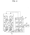
- Fig.2 illustrates the electrical makeup of the biped walking robot 10 shown in Fig.1.
- the biped walking robot 10 is provided with a gait forming part 24 to form gait data corresponding to the targeted motion, and a walk controller 30 to drive-control a drive means, namely the above-mentioned respective joint portions, that is, the joint driving motors 15L, 15R, to 20L, 20R based on the gait data.
- xyz coordinate system is used as that for the biped walking robot 10 with x direction as anteroposterior direction (forward as +), with y direction as horizontal direction (inner direction as +), and with z direction as vertical direction (upward direction as +).
- the gait forming part 24 forms the gait data, responding to the targeted motion input from the outside, including target angle path, target angle velocity, and target angle acceleration of respective joint portions 15L, 15R, to 20L, 20R required for the biped walking robot 10 to walk.
- the walk controller 30 comprises an angle measurement unit 31, a compensation part 32, a controlling part 33, and a motor controlling unit 34.
- the angle measurement unit 31 is to measure the angular positions of respective joint drive motors, that is, the state vector ⁇ about angle and angle velocity, and outputs to the compensation part 32, by inputting the angular information of respective joint drive motors from, for example, a rotary encoder or the like provided to the joint drive motors of respective joint portions 15L, 15R to 20L, 20R.
- the compensation part 32 as shown in Fig.3, is provided with a hexaxial force computing part 32a, a contact detection part 32b, and a main compensation unit 32c.
- the hexaxial force computing part 32a outputs the hexaxial force (Fx, Fy, Fz, Tx, Ty, and Tz) to the main compensation unit 32c based on the detected output from force sensor parts 23L, 23R.
- the contact detection part 32b also decomposes the force components based on the detected output from the force sensor parts 23L, 23R, judges if each detected output from each force sensor part 23L, 23R is by the force from the floor surface, or by the contact to a matter on the floor surface, and, referring to the sensor makeup information recorded in advance in a sensor makeup information part 32d, judges which force sensor 36a, 36b, 36c, or 36d (mentioned later) of respective force sensor part 23L, 23R detected the contact of a foot side, and then outputs the flag information of said force sensor to the main compensation unit 32c.
- the contact detection part 32b outputs the output signals ⁇ Swx(0), Swy(0), Swz(0); Swx(1), Swy(1), Swz(1); ⁇ , and outputs the flag information of respective force sensors by setting the flag of the output signal from a force sensor which detected the contact of a foot side, as, for example, from 0 to 1.
- the controlling part 33 forms control signals of respective joint drive motors, that is, torque vectors ⁇ based on the vector ( ⁇ i - ⁇ 0), by subtracting the angular vector ⁇ 0 at a robot's respective joint portions from the vector ⁇ i which is the gait data corrected by the compensation part 32. Further, the motor controlling unit 34 drive-controls respective joint drive motors according to the control signals (the torque vectors ⁇ ) from the controlling part 33.
- the force sensor part 23L comprises four force sensors 36a, 36b, 36c, and 36d, made up by horizontally divided, namely, two divisions in x direction and two divisions in y direction at the bottom of the sole plate 35 which is the bottom face of a foot portion 14L. Since each of the force sensors 36a, 36b, 36c, and 36d is of identical structure, explanation is made below of the force sensor 36a.
- the force sensor 36a is a 3-axis force sensor provided between a sole 37 above and a sole 38 below, and detects the force received by the lower sole 38.
- the lower sole 38 is supported pivotally movably to the front and behind, the left and right, with a sensor axis of the force sensor 36a as the center, and is so designed as to be capable of landing in all directions by pivoting, and is provided with a side wall 38a rising upward at a part next to the outer edge, namely, a foot side of a foot portion 14L. Therefore, when a foot portion 14L hits a side of a matter on the floor surface, the side wall 38a of the lower sole 38 collides on said matter, transmits its impact strength to the force sensor 36a, which can hence detect said contact.
- force sensor parts 23L and 23R are divided, respectively, into four force sensors 36a to 36d, but not limited as such, they may be divided at least into four at both sides of heel portions 14L, 14R, and both sides of toe portions of foot portions, and furthermore, may be divided into five or more. Also, each of the force sensors 36a to 36d is located in line at a sole, as illustrated in a figure, but not limited as such, may be located arbitrarily.
- the above-mentioned force sensors 36a to 36d are 3-axis force sensors, and with two or more 3-axis force sensors, the hexaxial directional force can be computed.
- Fig.5 of computation of hexaxial directional force from 3-axis force sensors of n in number in general.
- 3-axis force sensors of n in number S1, S2, S3, ---, Sn are arranged at a sole with respect to the origin O (Ox, Oy) of force measurement.
- the origin O of force measurement preferably better agrees, for example, to the drive coordinate system of a foot joint.
- the hexaxial force computing part 32a provided in the compensation part 32 based on the detected output from each of 3-axis force sensors 36a to 36d, and the forces in hexaxial direction are detected.
- the horizontal floor reaction force F is expressed as the force in horizontal direction generated from the friction between the floor surface and a robot 10's sole, namely, a resultant force of Fx in X direction and Fy in Y direction, and its vector Fc and its magnitude
- each of the 3-axis force sensors 36a to 36d has data dispersion in respective detected output, as well as the detected output varies by the environmental temperature and the secular distortion and others. Therefore, the detected output from each of the 3-axis force sensors 36a to 36d is automatically calibrated in the compensation part 32 by, for example, auto-calibration.
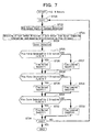
- the biped walking robot 10 in accordance with the embodiment of the present invention is constituted as described above, and its walking motion is conducted by the flowchart shown in Fig.6 as described below.
- the force sensor 23L, 23R provided to both foot portions 14L, 14R detect forces respectively, and output to the hexaxial force computing part 32a and the contact detection part 32b of the compensation part 32.
- the angle measurement unit 31 measures the state vector ⁇ of respective joint portions 15L, 15R to 20L, 20R, and outputs to the compensation part 32.
- the hexaxial force computing part 32a computes hexaxial force based on the detected output from respective force sensors 36a to 36d of force sensor parts 23L, 23R, and outputs to the main compensation unit 32c.
- the contact detection part 32b as described below based on the detected output from respective force sensors 36a to 36d of force sensor parts 23L, 23R, judges which of the force sensors 36a to 36d detects the contact of a foot side, and outputs the flag information of said force sensors 36a to 36d to the main compensation unit 32c.
- the main compensation unit 32c of the compensation part 32 computes horizontal floor reaction force F based on the hexaxial force from the hexaxial force computing part 32a.
- the main compensation unit 32c of the compensation part 32 adjusts the gait data, while referring to the flag information from the contact detection part 32b, based on said horizontal floor reaction force F and the state vector ⁇ of respective joint portions 15L, 15R to 20L, 20R from the angle measurement unit 31, and outputs the vector ⁇ i to the controlling part 33.
- the compensation part 32 may adjust the gait data by applying hexaxial force to the known ZMP compensation function.
- said known ZMP compensation function the international patent application (International Publication Number WO02/100606 A1) laid open on December 19, 2002 by the present applicant, for example, may be referred to.
- the gait data may be adjusted by applying hexaxial force to the conventional compensation function.
- the controlling part 33 subtracts an angle vector ⁇ 0 at respective joint portions from the vector ⁇ i, generates, based on the vector ( ⁇ i - ⁇ 0), the control signals for respective joint drive motors, namely, torque vectors ⁇ , and outputs to the motor control unit 34.
- the motor control unit 34 drive-controls the joint drive motors of respective joint portions based on the torque vectors ⁇ .
- the biped walking robot 10 conducts walk motions corresponding to the required motions.
- the direction of a foot center of the force sensor is obtained from the sensor composing information recorded in advance in the sensor composing information part 32d, and said direction is assumed as plus with respect to a three-axis.
- the force sensors 36a to 36d detect force
- the contact detection part 32b judges if the plus force is detected with respect to X direction (Fx(K)>0?)
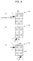
- the force sensors 36a and/or 36d are acting as touch sensors, respectively, thereby the contact detection is conducted by the contact detection part 32b.
- the gait data is adjusted, referring to the flag information showing the contact of a foot side by the contact detection part 32b, based on the horizontal floor reaction force F from the force sensor parts 23L, 23R provided to the soles of respective foot portions 14L, 14R in the main compensation unit 32c of the compensation part 32, and vector ⁇ i is generated, whereby the stability of the robot 10 is realized with said horizontal floor reaction force F as the reference model.
- the force sensor parts 23L, 23R provided to soles can detect the contact of foot sides, it would not continue walking motion as it has been doing, and fall down in some cases as in the prior cases, and it is possible to assuredly conduct walking motion according to the required motion.
- the biped walking robot 10 in accordance with this embodiment, by adjusting the gait data, based on the horizontal floor reaction force F computed from the detected signals from the force sensors 23L, 23R provided to the soles of respective foot portions 14L, 14R, namely, from the 3-axis force sensors 36a to 36d provided to the soles divided into plurality, and further referring to the detection of contact of foot sides by the contact detection part 32b, can conduct walk control with the horizontal floor reaction force F generated from the friction between a sole and the floor surface as the reference model.
- the force sensor parts 23L, 23R can be utilized as touch sensors about side faces, thereby contact of a foot side can be detected, the makeup is simplified, and the cost lowered, and the robot 10's walk stability can be realized even with an obstacle or a step on the floor surface.
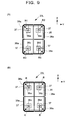
- the force sensor parts 23L, 23R have, as shown in Fig.4, the side wall 38a of the lower sole 38 of respective force sensors 36a to 36d having an outer shape of rectangle as a whole, but not limited as such as shown in Fig.9(A), at least a part of the side wall 38a of the lower sole 38 as a detecting part, the corner parts in case of illustration in the figure may be formed as circular arc planes with the radii R1, R2, R3, and R4 with respective force sensors 36a, 36b, 36c, and 36d as centers.
- the robot's stability can be maintained by detecting the contact of foot sides, and adjusting the gait data, and hence the walk control can be assuredly conducted without falling down, thereby an extremely superb biped walking mobile system, its walk controller, and the method of walk control are provided.
Landscapes
- Engineering & Computer Science (AREA)
- Mechanical Engineering (AREA)
- Robotics (AREA)
- Human Computer Interaction (AREA)
- Chemical & Material Sciences (AREA)
- Combustion & Propulsion (AREA)
- Transportation (AREA)
- Manipulator (AREA)
- Toys (AREA)
Applications Claiming Priority (3)
| Application Number | Priority Date | Filing Date | Title |
|---|---|---|---|
| JP2002172109 | 2002-06-12 | ||
| JP2002172109A JP3598507B2 (ja) | 2002-06-12 | 2002-06-12 | 歩行式移動装置及びその歩行制御装置及び歩行制御方法 |
| PCT/JP2003/007089 WO2003106112A1 (ja) | 2002-06-12 | 2003-06-04 | 歩行式移動装置及びその歩行制御装置並びに歩行制御方法 |
Publications (2)
| Publication Number | Publication Date |
|---|---|
| EP1552909A1 true EP1552909A1 (de) | 2005-07-13 |
| EP1552909A4 EP1552909A4 (de) | 2009-08-19 |
Family
ID=29727842
Family Applications (1)
| Application Number | Title | Priority Date | Filing Date |
|---|---|---|---|
| EP03736033A Withdrawn EP1552909A4 (de) | 2002-06-12 | 2003-06-04 | Schreitbewegungsvorrichtung und schreitsteuervorrichtung dafür sowie schreitsteuerverfahren |
Country Status (7)
| Country | Link |
|---|---|
| US (1) | US20050171635A1 (de) |
| EP (1) | EP1552909A4 (de) |
| JP (1) | JP3598507B2 (de) |
| KR (1) | KR100608983B1 (de) |
| CN (1) | CN100588509C (de) |
| TW (1) | TW589245B (de) |
| WO (1) | WO2003106112A1 (de) |
Cited By (2)
| Publication number | Priority date | Publication date | Assignee | Title |
|---|---|---|---|---|
| EP2033612A4 (de) * | 2006-06-12 | 2009-06-24 | Honda Motor Co Ltd | Kontrollvorrichtung für eine gehhilfevorrichtung |
| EP1792597A4 (de) * | 2004-08-27 | 2012-10-10 | Honda Motor Co Ltd | Kontrollvorrichtung für eine gehhilfe |
Families Citing this family (13)
| Publication number | Priority date | Publication date | Assignee | Title |
|---|---|---|---|---|
| JP5104355B2 (ja) * | 2008-02-01 | 2012-12-19 | 富士通株式会社 | ロボット制御装置、ロボット制御方法およびロボット制御プログラム |
| JP5379304B2 (ja) * | 2009-07-01 | 2013-12-25 | レックス バイオニクス リミテッド | 移動補助器械用制御システム |
| KR101262978B1 (ko) * | 2011-12-05 | 2013-05-08 | 현대자동차주식회사 | 보행로봇의 반발력 측정 모듈 및 방법 |
| DE112014006117T5 (de) * | 2014-01-07 | 2016-10-06 | Asahi Kasei Kabushiki Kaisha | Laufrichtung-Bestimmungsvorrichtung, Kartenabgleichvorrichtung, Laufrichtung-Bestimmungsverfahren und Programm |
| US9618937B1 (en) * | 2014-08-25 | 2017-04-11 | Google Inc. | Slip detection using robotic limbs |
| US9499218B1 (en) | 2014-12-30 | 2016-11-22 | Google Inc. | Mechanically-timed footsteps for a robotic device |
| US9778132B1 (en) * | 2015-12-16 | 2017-10-03 | X Development Llc | Methods and systems for force sensor calibration |
| CN106217352A (zh) * | 2016-08-17 | 2016-12-14 | 尖叫智能科技(上海)有限公司 | 基于压力传感器的外骨骼机器人步态控制方法 |
| US11498216B2 (en) * | 2017-09-22 | 2022-11-15 | Mitsubishi Electric Corporation | Remote control manipulator system and control device |
| CN109693236B (zh) * | 2017-10-23 | 2021-03-02 | 深圳市优必选科技有限公司 | 足式机器人着地控制方法及装置 |
| EP4011175A1 (de) * | 2019-08-06 | 2022-06-15 | Boston Dynamics, Inc. | Erfassung von trittstufenkontakt |
| CN111267993B (zh) * | 2020-01-19 | 2021-04-27 | 之江实验室 | 一种双足机器人的足部结构及其全地形路面适应方法 |
| CN114486037A (zh) * | 2022-02-18 | 2022-05-13 | 橙象医疗科技(广州)有限公司 | 一种具有测力装置的路况模拟设备及其控制方法 |
Family Cites Families (24)
| Publication number | Priority date | Publication date | Assignee | Title |
|---|---|---|---|---|
| US3655003A (en) * | 1970-09-23 | 1972-04-11 | Tanita Seisakusho Kk | Weighing machine |
| JP2520019B2 (ja) * | 1989-06-29 | 1996-07-31 | 本田技研工業株式会社 | 脚式移動ロボットの駆動制御装置 |
| US5255753A (en) * | 1989-12-14 | 1993-10-26 | Honda Giken Kogyo Kabushiki Kaisha | Foot structure for legged walking robot |
| JP2826858B2 (ja) * | 1989-12-14 | 1998-11-18 | 本田技研工業株式会社 | 脚式歩行ロボットの足部構造 |
| US5432417A (en) * | 1992-04-30 | 1995-07-11 | Honda Giken Kogyo Kabushiki Kaisha | Locomotion control system for legged mobile robot |
| JP3132156B2 (ja) * | 1992-05-22 | 2001-02-05 | 本田技研工業株式会社 | 脚式移動ロボットの歩容生成装置 |
| JP3269852B2 (ja) * | 1992-05-29 | 2002-04-02 | 本田技研工業株式会社 | 脚式移動ロボットの姿勢安定化制御装置 |
| JP3278467B2 (ja) * | 1992-08-18 | 2002-04-30 | 本田技研工業株式会社 | 移動ロボットの制御装置 |
| JP3055737B2 (ja) * | 1992-08-28 | 2000-06-26 | 本田技研工業株式会社 | 脚式移動ロボットの歩行制御装置 |
| FR2697492B1 (fr) * | 1992-11-05 | 1994-12-23 | Commissariat Energie Atomique | Pied de robot marcheur. |
| US5808433A (en) * | 1995-09-29 | 1998-09-15 | Honda Giken Kogyo Kabushiki Kaisha | Method of generating gait of legged walking robot and system for controlling its locomotion |
| JP3405868B2 (ja) | 1995-09-29 | 2003-05-12 | 本田技研工業株式会社 | 脚式歩行ロボットの歩容生成方法 |
| DE69725764T2 (de) * | 1996-07-25 | 2004-08-05 | Honda Giken Kogyo K.K. | Vorrichtung zur nachbildung des ganges für einen zweibeinigen robotor |
| US6243623B1 (en) * | 1997-01-31 | 2001-06-05 | Honda Giken Kogyo Kabushiki Kaisha | Leg type mobile robot control apparatus |
| US6625846B2 (en) * | 1998-03-06 | 2003-09-30 | Shigeo Takizawa | Caster for robot |
| DE69943148D1 (de) * | 1998-04-20 | 2011-03-03 | Honda Motor Co Ltd | Steuereinheit für einen mit beinen beweglichen roboter |
| JP3443077B2 (ja) * | 1999-09-20 | 2003-09-02 | ソニー株式会社 | ロボットの運動パターン生成装置及び運動パターン生成方法、並びにロボット |
| JP4279425B2 (ja) * | 1999-11-05 | 2009-06-17 | 本田技研工業株式会社 | 脚式歩行ロボットの足部構造 |
| JP3615702B2 (ja) * | 1999-11-25 | 2005-02-02 | ソニー株式会社 | 脚式移動ロボットの動作制御装置及び動作制御方法、並びに、脚式移動ロボット |
| JP2001239479A (ja) * | 1999-12-24 | 2001-09-04 | Sony Corp | 脚式移動ロボット及びロボットのための外装モジュール |
| JP3634238B2 (ja) * | 2000-05-19 | 2005-03-30 | 本田技研工業株式会社 | 脚式移動ロボットの床形状推定装置 |
| TW499349B (en) * | 2000-11-17 | 2002-08-21 | Sony Corp | Legged mobile robot, leg structure of legged mobile robot, and mobile leg unit for legged mobile robot |
| WO2002045913A1 (en) * | 2000-11-20 | 2002-06-13 | Sony Corporation | Device and method for controlling operation of legged robot, and robot device |
| US20020193045A1 (en) * | 2001-05-08 | 2002-12-19 | Lee James S. W. | Toy robot apparatus and method |
-
2002
- 2002-06-12 JP JP2002172109A patent/JP3598507B2/ja not_active Expired - Fee Related
-
2003
- 2003-06-04 WO PCT/JP2003/007089 patent/WO2003106112A1/ja not_active Ceased
- 2003-06-04 EP EP03736033A patent/EP1552909A4/de not_active Withdrawn
- 2003-06-04 KR KR1020047020023A patent/KR100608983B1/ko not_active Expired - Fee Related
- 2003-06-04 CN CN03813606A patent/CN100588509C/zh not_active Expired - Fee Related
- 2003-06-04 US US10/517,377 patent/US20050171635A1/en not_active Abandoned
- 2003-06-09 TW TW092115501A patent/TW589245B/zh not_active IP Right Cessation
Cited By (3)
| Publication number | Priority date | Publication date | Assignee | Title |
|---|---|---|---|---|
| EP1792597A4 (de) * | 2004-08-27 | 2012-10-10 | Honda Motor Co Ltd | Kontrollvorrichtung für eine gehhilfe |
| EP2033612A4 (de) * | 2006-06-12 | 2009-06-24 | Honda Motor Co Ltd | Kontrollvorrichtung für eine gehhilfevorrichtung |
| US8303521B2 (en) | 2006-06-12 | 2012-11-06 | Honda Motor Co., Ltd. | Control device for walking assistance device |
Also Published As
| Publication number | Publication date |
|---|---|
| KR20050016533A (ko) | 2005-02-21 |
| CN1659002A (zh) | 2005-08-24 |
| KR100608983B1 (ko) | 2006-08-03 |
| WO2003106112A1 (ja) | 2003-12-24 |
| JP2004017180A (ja) | 2004-01-22 |
| JP3598507B2 (ja) | 2004-12-08 |
| TW589245B (en) | 2004-06-01 |
| CN100588509C (zh) | 2010-02-10 |
| US20050171635A1 (en) | 2005-08-04 |
| TW200405844A (en) | 2004-04-16 |
| EP1552909A4 (de) | 2009-08-19 |
Similar Documents
| Publication | Publication Date | Title |
|---|---|---|
| EP1464451B1 (de) | Zweibeinige schreitbewegungsvorrichtung und schreitsteuervorrichtung und -verfahren dafür | |
| EP1477283A1 (de) | Zweibeinige schreit-fortbewegungsvorrichtung und ihre schreitsteuerung | |
| JP3634238B2 (ja) | 脚式移動ロボットの床形状推定装置 | |
| EP1053835B1 (de) | Steuergerät eines mit beinen beweglichen roboters | |
| EP1721711B1 (de) | Gangerzeuger für mobilen roboter | |
| EP1649983B1 (de) | Gangerzeugungsvorrichtung für beweglichen roboter mit beinen | |
| JP3901694B2 (ja) | 歩行式ロボット及びその位置移動方法 | |
| EP1291137A1 (de) | Vorrichtung zur feststellung des bodenprofils für bewegliche roboter mit beinen | |
| US20050171635A1 (en) | Walking type moving device and walking control device therefor and walking control method | |
| EP1842628B1 (de) | Mit beinen versehener mobiler roboter | |
| EP1844908B1 (de) | Mit beinen ausgestatteter mobiler roboter und steuerprogramm für den roboter | |
| EP1733852B1 (de) | Gangerzeugungsvorrichtung für beweglichen roboter | |
| EP1736286B1 (de) | Gangerzeugungsvorrichtung für beweglichen roboter | |
| EP1844907B1 (de) | Mit beinen ausgestatteter mobiler roboter und steuerprogramm für den roboter | |
| JP3167406B2 (ja) | 脚式移動ロボットの歩行制御装置 | |
| JP3024023B2 (ja) | 脚式移動ロボットの歩行制御装置 | |
| JP3760198B2 (ja) | 歩行式移動装置及びその歩行制御装置及び歩行制御方法 | |
| JP3183557B2 (ja) | 脚式移動ロボットの歩行制御装置 |
Legal Events
| Date | Code | Title | Description |
|---|---|---|---|
| PUAI | Public reference made under article 153(3) epc to a published international application that has entered the european phase |
Free format text: ORIGINAL CODE: 0009012 |
|
| 17P | Request for examination filed |
Effective date: 20050107 |
|
| AK | Designated contracting states |
Kind code of ref document: A1 Designated state(s): AT BE BG CH CY CZ DE DK EE ES FI FR GB GR HU IE IT LI LU MC NL PT RO SE SI SK TR |
|
| AX | Request for extension of the european patent |
Extension state: AL LT LV MK |
|
| DAX | Request for extension of the european patent (deleted) | ||
| RBV | Designated contracting states (corrected) |
Designated state(s): DE FR GB NL |
|
| A4 | Supplementary search report drawn up and despatched |
Effective date: 20090720 |
|
| 17Q | First examination report despatched |
Effective date: 20090915 |
|
| STAA | Information on the status of an ep patent application or granted ep patent |
Free format text: STATUS: THE APPLICATION IS DEEMED TO BE WITHDRAWN |
|
| 18D | Application deemed to be withdrawn |
Effective date: 20101111 |