EP1552970A1 - Aufhängung mit einstellbarer Kraft - Google Patents
Aufhängung mit einstellbarer Kraft Download PDFInfo
- Publication number
- EP1552970A1 EP1552970A1 EP04290026A EP04290026A EP1552970A1 EP 1552970 A1 EP1552970 A1 EP 1552970A1 EP 04290026 A EP04290026 A EP 04290026A EP 04290026 A EP04290026 A EP 04290026A EP 1552970 A1 EP1552970 A1 EP 1552970A1
- Authority
- EP
- European Patent Office
- Prior art keywords
- force
- vertical
- wheel support
- elastic
- suspended mass
- Prior art date
- Legal status (The legal status is an assumption and is not a legal conclusion. Google has not performed a legal analysis and makes no representation as to the accuracy of the status listed.)
- Withdrawn
Links
- 239000000725 suspension Substances 0.000 title claims abstract description 67
- 238000000034 method Methods 0.000 claims abstract description 23
- 238000006073 displacement reaction Methods 0.000 claims abstract description 22
- 238000013016 damping Methods 0.000 claims description 15
- 238000004364 calculation method Methods 0.000 claims description 12
- 230000008878 coupling Effects 0.000 claims description 6
- 238000010168 coupling process Methods 0.000 claims description 6
- 238000005859 coupling reaction Methods 0.000 claims description 6
- 239000003381 stabilizer Substances 0.000 abstract 1
- 230000003068 static effect Effects 0.000 description 10
- 238000005086 pumping Methods 0.000 description 7
- 239000006096 absorbing agent Substances 0.000 description 6
- 230000035939 shock Effects 0.000 description 6
- 238000001914 filtration Methods 0.000 description 5
- 230000005484 gravity Effects 0.000 description 5
- 238000005259 measurement Methods 0.000 description 5
- 230000006835 compression Effects 0.000 description 4
- 238000007906 compression Methods 0.000 description 4
- 238000004519 manufacturing process Methods 0.000 description 4
- 238000012937 correction Methods 0.000 description 3
- 230000000694 effects Effects 0.000 description 3
- 230000008569 process Effects 0.000 description 3
- 230000004044 response Effects 0.000 description 3
- 230000001133 acceleration Effects 0.000 description 2
- 230000009471 action Effects 0.000 description 2
- 238000006243 chemical reaction Methods 0.000 description 2
- 230000006872 improvement Effects 0.000 description 2
- 238000010606 normalization Methods 0.000 description 2
- 238000005096 rolling process Methods 0.000 description 2
- 238000012360 testing method Methods 0.000 description 2
- 230000009466 transformation Effects 0.000 description 2
- 230000000712 assembly Effects 0.000 description 1
- 238000000429 assembly Methods 0.000 description 1
- 238000012550 audit Methods 0.000 description 1
- 238000004422 calculation algorithm Methods 0.000 description 1
- 230000000295 complement effect Effects 0.000 description 1
- 230000001419 dependent effect Effects 0.000 description 1
- 238000009795 derivation Methods 0.000 description 1
- 239000012530 fluid Substances 0.000 description 1
- 238000002513 implantation Methods 0.000 description 1
- 238000007726 management method Methods 0.000 description 1
- 230000005226 mechanical processes and functions Effects 0.000 description 1
- 230000004048 modification Effects 0.000 description 1
- 238000012986 modification Methods 0.000 description 1
- 210000000056 organ Anatomy 0.000 description 1
- 210000004417 patella Anatomy 0.000 description 1
- 239000004033 plastic Substances 0.000 description 1
- 230000002040 relaxant effect Effects 0.000 description 1
- 238000005070 sampling Methods 0.000 description 1
- 238000000844 transformation Methods 0.000 description 1
- 230000001052 transient effect Effects 0.000 description 1
Images



Classifications
-
- B—PERFORMING OPERATIONS; TRANSPORTING
- B60—VEHICLES IN GENERAL
- B60G—VEHICLE SUSPENSION ARRANGEMENTS
- B60G17/00—Resilient suspensions having means for adjusting the spring or vibration-damper characteristics, for regulating the distance between a supporting surface and a sprung part of vehicle or for locking suspension during use to meet varying vehicular or surface conditions, e.g. due to speed or load
- B60G17/06—Characteristics of dampers, e.g. mechanical dampers
- B60G17/08—Characteristics of fluid dampers
-
- B—PERFORMING OPERATIONS; TRANSPORTING
- B60—VEHICLES IN GENERAL
- B60G—VEHICLE SUSPENSION ARRANGEMENTS
- B60G17/00—Resilient suspensions having means for adjusting the spring or vibration-damper characteristics, for regulating the distance between a supporting surface and a sprung part of vehicle or for locking suspension during use to meet varying vehicular or surface conditions, e.g. due to speed or load
- B60G17/015—Resilient suspensions having means for adjusting the spring or vibration-damper characteristics, for regulating the distance between a supporting surface and a sprung part of vehicle or for locking suspension during use to meet varying vehicular or surface conditions, e.g. due to speed or load the regulating means comprising electric or electronic elements
- B60G17/0152—Resilient suspensions having means for adjusting the spring or vibration-damper characteristics, for regulating the distance between a supporting surface and a sprung part of vehicle or for locking suspension during use to meet varying vehicular or surface conditions, e.g. due to speed or load the regulating means comprising electric or electronic elements characterised by the action on a particular type of suspension unit
Definitions
- the present invention relates to a method of control of a suspension actuator with adjustable force in a vehicle and a vehicle suspension device automobile.
- US-A-5510988 discloses a control method according to in the preamble of claim 1 and a suspension device according to the preamble of claim 7.
- This device produces control signals for the suspension actuators, which are semi-active dampers, in response to relative velocities between the wheels and the mass suspended at the four corners of the vehicle.
- the suspension device tends to reduce movements of the suspension mass of the vehicle in relation to a static reference, according to the principle of the "air cart”.
- Forces setback damping also called stress requests depreciation, are based on estimates of absolute speed of the suspended mass of the vehicle, namely the pumping speed, the angular rate of roll and pitch angular velocity.
- McPherson struts springs are used.
- the forces of the springs are not taken into account in the calculation of the requests for depreciation effort.
- the force provided by the damper is not largely preponderant on the strength of the springs, for example in the case of a strong vertical displacement amplitude of the wheel or in the case where the wheel support is coupled to relatively stiff springs. This results in some inaccuracy the control of the suspended mass.
- the present invention aims to improve control suspension actuators in the aforementioned situations.
- the invention is also intended to provide a vehicle suspension device improving the trim of the suspended mass of the vehicle.
- said at least one vertical elastic force is determined from predefined stiffness data, static or dynamic, of said at least one spring.
- said at least one spring includes a bar anti-roll coupling said wheel support to an opposite wheel support on the same axle of said vehicle, said method comprising the step determining a vertical displacement between said support opposite wheel and said suspended mass, said vertical elastic force exerted by said anti-roll bar being determined according to the vertical displacements of the two wheel supports.
- anti-roll bar the stiffness of which at the front of the vehicle is generally high, accentuates the improvement of mass control suspended in the roll movements.
- the vertical displacement is advantageously measured by a sensor responsive to a distance between said wheel support and said mass suspended.
- this displacement can also be calculated from the measurements provided by speed sensors or sensors acceleration.
- the force demand is calculated according to of the difference between a vertical setpoint force to be applied between said suspended mass and said wheel support and a elastic vertical force exerted by said at least one spring between said suspended mass and said wheel support.
- said minus a vertical setpoint force and said at least one force elastic vertical are determined modally according to at least a predetermined mode of movement of said suspended mass, the force demand being calculated according to the difference between said or each modal command vertical force and said or each force vertical modal elastic corresponding.
- the force determining means vertical elastic contain predefined stiffness data of said at least one spring.
- said at least one spring includes a spring mounted in parallel with said suspension actuator, such as for example that a strut spring.
- said at least one spring includes a bar antiroll coupling said wheel support to an opposite wheel support on the same axle of said vehicle, said device further comprising a sensor responsive to vertical movement between said suspended mass and said opposite wheel support, said force determining means elastic vertical being able to determine said vertical elastic force exerted by said antiroll bar according to displacements vertical of the two wheel supports.
- said adjustable force suspension actuator is a shock absorber to adjustable damping
- said control means further including a comparator for comparing the meaning of said demand for force and the direction of variation of the elongation of said damper, said means of control being able to adjust said damper according to the result of said comparison.
- FIG. 1 there is shown a motor vehicle 1 equipped with a semi-active suspension device that is a modification of the suspension device described in US-A-5510988.
- the vehicle 1 includes a rigid box 2 carried in a suspended manner by four 3 wheels via four struts 4 of known type.
- Each strut 4 comprises a suspension actuator 5 to adjustable force that can be controlled in real time, which is interposed between a corner area of the body 2 and a wheel support member 6, schematically represented in broken lines.
- the element 6 is a conventional suspension lower arm.
- the suspension actuator 5 is a semi-active damper to continuously variable electric drive, as described in US Patent 5,282,645.
- Many other types of semi-active dampers are known and suitable for the implementation of the invention, as the magneto-rheological fluid dampers.
- Each strut 4 also includes a spring helical 7 interposed directly or indirectly between the body 2 and the support element 6 in parallel with the suspension actuator 5.
- the spring 7 is mounted around the actuator of suspension 5 and constrained between the two parts with relative movement of the suspension actuator 5.
- Each strut 4 finally includes elastic end stops 10, typically made of rubber, which come into action during large-scale deflections of the strut 4. In addition to compression limit stops 10, there are also relaxing end stops in the cylinder of the suspension actuator 5.
- Each axle of the vehicle 1 also has a bar conventional anti-roll 8 with both ends coupled directly or indirectly to the two support elements 6 mutually opposed.
- the anti-roll bar 8 is moreover known manner to the box 2 at the level of fasteners 9.
- the configuration and the method of assembling the strut 4, the support member 6 and the anti-roll bar 8 can be of any type and therefore are not shown in detail in Figure 1.
- Each corner of the vehicle 1 includes a position sensor 11 which produces a measurement signal 12 indicating the vertical distance relative between the wheel support 6 and the body 2 of the vehicle.
- the sensor 11 includes a resistive device fixed to the body 2 at the corresponding wedge level and a coupled coupling member pivoting between the wheel support 6 and a swivel arm of the apparatus resistive, which produces an impedance signal that varies with the distance relative vertical line between the wheel support 6 and the body 2 of the vehicle at corresponding corner level.
- the measurement signals 12 of the position sensors 11 are entered a suspension control unit 13 provided with a microprocessor 14 which processes these signals to determine the state dynamic of the body 2 and generate control signals 15 for the suspension actuators 5.
- the control unit 13 transmits these control signals by appropriate electrical connections in time real.
- the control unit 13 can use other signals input, for example a lateral acceleration signal provided by a sensor 16, a pitch signal provided by a sensor 17, a signal of speed provided by a sensor 18 and a steering wheel angle signal of direction provided by a sensor 19.
- Such sensors are well known.
- the unit 13 includes a microcontroller 20 which is programmed to execute a calculation algorithm so as to produce the signals of order 15 for the suspension actuators 5.
- the unit 13, which is represented in the form of functional blocks in Figure 2 can be achieved by any suitable combination circuit elements and / or software elements.
- the upper half of FIG. 2 shows a portion of the control unit 13 devoted to calculating, from the signals 12 supplied by the position sensors 11, vertical forces from the setpoint FC 1 to FC 4 .
- the target forces FC 1 to FC 4 which are produced in the form of corresponding signals at the output of the reference force calculation module 21, are forces that it is desired to apply between the support elements 6 of the wheels and the body 2, in particular using the suspension actuators 5.
- These set forces FC 1 to FC 4 correspond to the desired forces F i obtained at the end of the step 173 shown in FIG. A-5,510,988. Since this part of the control unit produces the target forces FC 1 to FC 4 in the same way as the forces Fi in US-A-5,510,988 are calculated, it will be described briefly. below.
- the position signals 12 of the four sensors 11 are respectively subjected to a low pass filtering then to a derivation time by analog circuits 22.
- the resulting speed signals are respectively digitized by an analog / digital converter 23 of the microcontroller 20, and then subjected to high-pass filtering by filters 24 to eliminate any continuous offset introduced during the digitization.
- the resulting signals rv 1 , rv 2 , rv 3 and rv 4 respectively represent the instantaneous relative vertical speed between each wheel support member 6 and the corresponding corner area of the body 2.
- a geometrical transformation module 25 converts the relative speed rv 1 to rv 4 in the modal relative speed signals of the body 2, namely a relative pump speed signal RV H , a relative rotational angular velocity signal RV R , and a relative pitch angular velocity signal RV P.
- the calculation of the modal relative speeds of the body 2 is carried out according to the following equations:
- RV H (rv 1 + rv 2 ) * (b / a + b) / 2 + (rv 3 + rv 4 ) * (a / a + b) / 2, where a denotes the body length between the center of gravity G and the axis of the front wheels of the vehicle and b denotes the body length between the center of gravity G and the axis of the rear wheels of the vehicle.
- RV R (rv 1 -rv 2 + rv 4 -rv 3 ) / 2T, where T denotes the track width measured between the wheel centers of the same axle.
- RV P (Rv 3 rV + 4 -rv 1 -rv 2 ) / (2a + 2b).
- the modal relative speed signals RV H , RV R and RV P are respectively filtered by digital low-pass filters 26, 27 and 28 to obtain phase-corrected signals H ', R' and P ', which represent the modal speeds. of the body 2 according to the modes of pumping, rolling and pitching.
- the setpoint calculation module 21 uses the absolute speed signals H ', R' and P 'and the relative speed signals rv 1 to rv 4 to calculate the target forces FC 1 to FC 4 .
- each elastic force signal FE i represents the instantaneous vertical force exerted by the set of springs acting between one of the wheel support elements 6 and the body 2, namely in the embodiment shown: a spring 7, a torsion bar 8 and resilient stops 10 each time.
- An analog / digital converter 29 digitizes position signals 12.
- a normalization module 30 processes each position signal 12 so as to add a continuous shift then to apply an appropriate scale factor to the signal.
- the normalization module 30 serves to obtain, from each position signal 12 measured by the sensors 11, a signal representing the vertical position of the wheel support member 6 expressed in relation to a known predetermined reference fixed by referred to the box 2 and in a known predetermined measuring unit.
- the offset and scale factor to be applied to each signal were previously stored in the microcontroller 20 on the production line of the vehicle 1.
- the standard position signals 31F of the front wheels are transmitted to elastic force calculation modules 32D, 32G and 32B.
- the module 32D receives the normalized position signal of the element of 6 front right wheel support and uses stiffness data representing the elastic behavior of the spring 7 and the stops 10 for calculate, from this position signal, the vertical force exerted by the spring 7 and the stops 10 between the wheel support member 6 and the zone corresponding corner of the box 2.
- Figure 4 illustrates schematically this calculation.
- the abscissa Z represents the normalized position of the wheel support 6 relative to the body 2 and the ordinate FRD represents the elastic vertical force.
- the curve 33 represents the static stiffness of the combination spring 7 and stops 10. On the curve 33, the end stops 10 of the strut 4 only come into action beyond a displacement Z 1 , which explains the slope break at this point.
- the stiffness data used by the 32D module consist for example of the curve 33, or at least an appropriate sampling thereof. They were previously stored in the microcontroller 20 on the production line of the vehicle. These stiffness data can be determined, for a given vehicle model, by measurement in a test laboratory.
- a known positional reference of the support element of wheel 6 is necessary for the stiffness curve 33 is usable. In However, there is no obligation to fix this reference at the level of the position static balance of the spring 7.
- the position reference can be any. In practice, it is advantageous to set the reference of position by lifting the vehicle off the ground by means of an elevator for let the wheels hang under their own weight. Similarly, nothing obliges the stiffness curve 33 to be symmetrical, nor to be linear.
- the curve of stiffness 33 preferably represents the actual behavior or the most realistic possible of spring 7 and stops 10.
- dynamic stiffness data may be used to account for changes in the behavior of the springs as a function of the frequency of the exciter force.
- the modules 32 will be provided with additional inputs to receive the speeds rv i necessary for determining the corresponding frequencies.
- the 32G module operates in the same way as the element 32D, but for the front left wheel support member 6. In the case where the front struts are identical, the 32D and 32G modules can therefore be identical. This is not necessary, however.
- the module 32B receives the normalized position signals 31F of the two front wheel support members and uses data from stiffness representing the elastic behavior of the anti-roll bar 8 before to calculate the torque exerted by the anti-roll bar 8 on the body 2. As for springs 7 and stops 10, the stiffness data have been previously stored in the microcontroller 20 on the production line of the vehicle. Schematically, the anti-roll bar before 8 transmits a couple of body roll 2 in response to vertical differential movements two front wheel support elements 6.
- the anti-roll bar 8 does not necessarily act to the same areas of the box 2 that struts 4. In fact, each spring usually exerts his elastic force at a different point from the others springs. So that we can easily combine the efforts of different springs acting on a wheel support, modules 32D, 32G and 32B calculate each time an elastic force reported at the center of the wheel using corresponding geometric transformations.
- Signals representing elastic vertical forces FRD, FBG and FBD are pass-filtered to remove any component of continuous force, which may result for example from that the vehicle 1 is launched in a constant curve for a duration several seconds.
- the control of the actuators suspension described here aims to reduce transient movements of the box 2.
- the cutoff frequency of filtering can be chosen for example between about 0.1 and 0.5 Hz.
- the filtered signals are then subjected to phase correction. Filtering high pass and phase correction are performed by modules 34.
- an adder 35 summed the signals representing the vertical forces FRD and FBD. This gives a signal FE 1 representing the vertical elastic force exerted on the right front corner area of the body 2 by the combination of the elastic members coupling the wheel support member 6 right front to the body, namely a spring 7 , an anti-roll bar 8 and possibly stops 10.
- the signal FE 1 Since the calculation of the signal FE 1 has been described above, it is sufficient to refer to this description to obtain the other elastic vertical force signals FE 2 to FE 4 corresponding to the other three corner zones of the body 2. Only changes, each time, the stiffness data to be used and the corresponding calculation modules. Thus, the signal FE 2 is obtained from the position signals 31F and the signals FE 3 and FE 4 are obtained from the position signals 31R of the rear wheel support elements. In each case, the elastic vertical force FE i is evaluated as a deviation from the static equilibrium situation of the springs supporting the weight of the suspended mass of the vehicle 1.
- the sign convention used to calculate the set force signals FC i and the elastic force signals FE i is the same, that is, for example, that a positive force tends to lower the corresponding corner area of the body 2 and a negative force tends to make it rise.
- control signals 15, for example in the form of pulse width modulated signals are transmitted by lines 38 to an output interface circuit 39, which routes the signals 15 to the shock absorbers 5.
- the strut 4 compresses and the body 2 begins to rise.
- the damping force of the damper 5 is oriented upwards: the damper 5 is in an active working dial.
- the control unit 13 adjusts its damping force to a minimum, for example by opening at most one channel between the compression chamber and the rebound chamber of the damper.
- the vertical setpoint force FC i corresponding to the damper 5 considered here depends on the details of the program of module 21. However, it can be considered that it is generally positive in this type of circumstance, namely that the control program requires that the body 2 is pulled down to oppose its pumping movement. Qualitatively, the vertical force of setpoint FC i can therefore be considered in general as similar to curve 40.
- the interval of the instant t 1 at time t 2 corresponds to the rebound movement of the damper 5, while the body 2 continues to rise.
- the damper 5 is therefore in a passive working dial.
- the vertical force of setpoint FC i is positive.
- the control unit 13 adjusts the force of the damper 5 according to the corresponding force demand D i .
- the spring 7 is compressed beyond its static equilibrium position, so that the corresponding elastic vertical force FE i is negative, the torsion bar not being taken into account. account in the example shown.
- Area 43 thus corresponds to the situation
- the taking into account of the force of the spring 7 leads to control the damper 5 so as to provide a greater damping force than in the control method of the prior art, since the spring 7 acts to the against the damping force of the damper 5 over the entire area 43.
- FIG. 7 a second embodiment of the control unit 13, in which the micro controller 120 is modified with respect to the microcontroller 20.
- the same reference numerals designate elements identical to those of the first embodiment, so we can refer to the previous description in their regard.
- the standardized position signals 31F and 31R of the wheels are transmitted to a module for determining the elastic modal forces 132.
- the module 132 uses modal stiffness parameters which represent the reaction of the set of springs 7, anti-roll bars 8 and stops 10 to the movements of the body 2 according to the modes of pumping, rolling and pitching. These stiffness parameters can be acquired, for a given vehicle model, by measurement in a test laboratory. They are previously stored in the microcontroller 120, for example on the production line of the vehicle.
- the module 132 calculates a pumping elastic force FE h which represents, at the center of gravity G of the suspended mass of the vehicle, the resultant of the contributions of all the aforementioned elastic members to the pumping mode, in terms of deviation from the static equilibrium position of the body 2.
- the module 132 also calculates a roll elastic moment FE r which represents the resultant at the level of center of gravity G of the contributions of all the aforementioned elastic members to the roll mode and an elastic moment of pitch FE p which represents the resultant at the level of the center of gravity G of the contributions of all the aforementioned elastic members to the pitching mode.
- the force signals FE r , FE h and FE p are subjected to high-pass filtering and phase correction by modules 134 operating in a manner similar to the modules 34 of the first embodiment.
- the modified set force calculation module 121 uses the absolute speed signals H ', R' and P 'and the relative speed signals rv 1 to rv 4 to calculate modal reference forces FC h according to the mode pumping, FC r according to the roll mode and FC p according to the pitch mode.
- the calculation method is similar to that implemented by the module 21, but with gains selected differently.
- the modal force signals DF h , DF r and DF p are passed to a geometric conversion module 45 which calculates a corresponding force demand signal D ' i for each of the dampers 5.
- On 1 DF h -DF p * A / (a + b) + DF r * T / 2
- On 2 DF h -DF p * A / (a + b) -DF r * T / 2
- On 3 DF h DF + p * B / (a + b) -DF r * T / 2
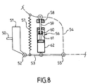
- Figure 8 schematically represents an example mechanical assembly involving several types of springs between a wheel and the body of a vehicle.
- the wheel not shown is fixed on the shaft 50 of the hub carrier 51 whose lower end is connected to a lower suspension arm 53 by a hinge 52, which can be a cylindrical elastic joint or patella.
- a suspension arm superior is not shown for clarity of the drawing.
- the arm of suspension 53 is connected to the body 54 by cylindrical elastic articulation 55.
- the semi-active damper 56 is interposed between the suspension arm 53 and the body 54, in parallel with a spring 57.
- the semi-active damper 56 has two types of stops: a compression stop 58 cylindrical, for example rubber, which is attached to the head of the rod shock absorber 59, and an expansion stop 60, for example made of plastic, which is mounted around the rod 59 in the cylinder 62 and supported by a washer 63 crimped on the rod 59.
- the stopper 60 can also take the form of a coil spring mounted around the rod 59 in the cylinder 62.
- several types of springs are likely to be solicited: the spring 57, the elastic articulation 55 and, the case the elastic articulation 52, and the stops 58 and 60.
- the effect of all will preferably be taken into account. these springs.
- the example shown in Figure 8 is not at all exhaustive. other types of springs may also be provided, like leaf springs, elastic bars, etc.
- the semi-active suspension device above has been described in details as to the control of the body of the vehicle according to the principle of "Air cart". However, such a suspension device can also fulfill other control functions, such as the control of wheels, stability control and energy management.
- the invention does not exclude the presence of these other controls having objectives complementary or alternative to the control of the fund according to the principle of the "air cart”.
- the implementation of multiple programs of control according to the internal and external events affecting the dynamic state of the vehicle is within the reach of the skilled person.
- Microcontrollers programmed 20 and 120, and more generally the control unit 13, can be made under the form of a combination of hardware and / or software components.
- a module can be realized in hardware and / or software, in one or several components.
- two modules do not match necessarily to two separate hardware or software components.
Landscapes
- Engineering & Computer Science (AREA)
- Mechanical Engineering (AREA)
- Vehicle Body Suspensions (AREA)
Priority Applications (1)
| Application Number | Priority Date | Filing Date | Title |
|---|---|---|---|
| EP04290026A EP1552970A1 (de) | 2004-01-07 | 2004-01-07 | Aufhängung mit einstellbarer Kraft |
Applications Claiming Priority (1)
| Application Number | Priority Date | Filing Date | Title |
|---|---|---|---|
| EP04290026A EP1552970A1 (de) | 2004-01-07 | 2004-01-07 | Aufhängung mit einstellbarer Kraft |
Publications (1)
| Publication Number | Publication Date |
|---|---|
| EP1552970A1 true EP1552970A1 (de) | 2005-07-13 |
Family
ID=34586006
Family Applications (1)
| Application Number | Title | Priority Date | Filing Date |
|---|---|---|---|
| EP04290026A Withdrawn EP1552970A1 (de) | 2004-01-07 | 2004-01-07 | Aufhängung mit einstellbarer Kraft |
Country Status (1)
| Country | Link |
|---|---|
| EP (1) | EP1552970A1 (de) |
Citations (10)
| Publication number | Priority date | Publication date | Assignee | Title |
|---|---|---|---|---|
| JPS6175008A (ja) * | 1984-09-20 | 1986-04-17 | Tokico Ltd | 懸架装置 |
| US4986568A (en) * | 1987-12-22 | 1991-01-22 | Automobiles Peugeot | Vehicle suspension with variable damping |
| FR2687201A1 (fr) * | 1992-02-10 | 1993-08-13 | Siemens Automotive Sa | Procede de commande d'un amortisseur et son utilisation dans un dispositif de suspension pour vehicule automobile. |
| US5282645A (en) | 1992-11-25 | 1994-02-01 | General Motors Corporation | Electro-hydraulic pressure regulating valve assembly mounted in a valve boss on a hydraulic damper |
| US5295074A (en) * | 1989-05-05 | 1994-03-15 | Group Lotus Plc | Vehicle suspension control system |
| US5510988A (en) | 1994-12-19 | 1996-04-23 | General Motors Corporation | Vehicle chassis control system |
| US5999868A (en) * | 1996-02-26 | 1999-12-07 | Board Of Regents The University Of Texas System | Constant force suspension, near constant force suspension, and associated control algorithms |
| US6206152B1 (en) * | 1998-03-06 | 2001-03-27 | Mannesmann Sachs Ag | Vibration damper with variable damping force |
| US6298293B1 (en) * | 1999-04-06 | 2001-10-02 | Toyoto Jidosha Kabushiki Kaisha | Kinetic state quantity estimating device and method for motor vehicle |
| US20020084599A1 (en) * | 2000-10-11 | 2002-07-04 | Jean-Jacques Charaudeau | Suspension device having electric actuator and spring in parallel |
-
2004
- 2004-01-07 EP EP04290026A patent/EP1552970A1/de not_active Withdrawn
Patent Citations (10)
| Publication number | Priority date | Publication date | Assignee | Title |
|---|---|---|---|---|
| JPS6175008A (ja) * | 1984-09-20 | 1986-04-17 | Tokico Ltd | 懸架装置 |
| US4986568A (en) * | 1987-12-22 | 1991-01-22 | Automobiles Peugeot | Vehicle suspension with variable damping |
| US5295074A (en) * | 1989-05-05 | 1994-03-15 | Group Lotus Plc | Vehicle suspension control system |
| FR2687201A1 (fr) * | 1992-02-10 | 1993-08-13 | Siemens Automotive Sa | Procede de commande d'un amortisseur et son utilisation dans un dispositif de suspension pour vehicule automobile. |
| US5282645A (en) | 1992-11-25 | 1994-02-01 | General Motors Corporation | Electro-hydraulic pressure regulating valve assembly mounted in a valve boss on a hydraulic damper |
| US5510988A (en) | 1994-12-19 | 1996-04-23 | General Motors Corporation | Vehicle chassis control system |
| US5999868A (en) * | 1996-02-26 | 1999-12-07 | Board Of Regents The University Of Texas System | Constant force suspension, near constant force suspension, and associated control algorithms |
| US6206152B1 (en) * | 1998-03-06 | 2001-03-27 | Mannesmann Sachs Ag | Vibration damper with variable damping force |
| US6298293B1 (en) * | 1999-04-06 | 2001-10-02 | Toyoto Jidosha Kabushiki Kaisha | Kinetic state quantity estimating device and method for motor vehicle |
| US20020084599A1 (en) * | 2000-10-11 | 2002-07-04 | Jean-Jacques Charaudeau | Suspension device having electric actuator and spring in parallel |
Non-Patent Citations (1)
| Title |
|---|
| PATENT ABSTRACTS OF JAPAN vol. 0102, no. 46 (M - 510) 23 August 1986 (1986-08-23) * |
Similar Documents
| Publication | Publication Date | Title |
|---|---|---|
| EP0780250B1 (de) | Feineinstellung eines MacPherson-Federbeines: Vorrichtung zur Einstellung auf dem Federbein und Bank zum Messen | |
| EP0878333B1 (de) | Aufhängungsvorrichtung mit Federkorrektureinheit | |
| FR2787066A1 (fr) | Systeme de suspension actif pour vehicules | |
| EP1197362B1 (de) | Aufhängungsvorrichtung mit einem elektrischen Stellantrieb mit einer parallelen Feder | |
| WO2004101311A1 (fr) | Suspension de siege active | |
| EP1363795A1 (de) | Aufhängungsvorrichtung für ein kraftfahrzeugrad | |
| FR2683185A1 (fr) | Appareil de reglage du coefficient d'amortissement des amortisseurs d'un vehicule. | |
| FR2784941A1 (fr) | Systeme de commande pour mecanisme de support elastique tel qu'un mecanisme de suspension pour vehicule | |
| FR2890904A1 (fr) | Dispositif de commande de suspension, vehicule muni de celui-ci, procede d'obtention et programme | |
| FR2719000A1 (fr) | Système de suspension actif, en particulier pour automobiles. | |
| FR2843194A1 (fr) | Procede et disposiitif de determination d'un effort exerce sur une roue par le sol | |
| FR2890902A1 (fr) | Dispositif de commande de suspension, vehicule muni de celui-ci, procede d'obtention et programme | |
| FR2890905A1 (fr) | Dispositif de commande de suspension, vehicule muni de celui-ci, procede d'obtention et programme. | |
| FR2798321A1 (fr) | Dispositif pour controler des amortisseurs de suspension de vehicules a l'aide de substituts virtuels places en biais | |
| EP3541644A1 (de) | Aufhängungsvorrichtung mit variabler fluidträgheit für eine fahrzeugachsensystem | |
| FR2945246A1 (fr) | Procede et dispositif de correction des vibrations d'un faisceau emis par un element optique de vehicule | |
| FR3084291A1 (fr) | Dispositif d'amortissement d'un vehicule et procede associe | |
| FR2935641A1 (fr) | Procede de configuration d'une caracteristique d'amortissement d'une suspension | |
| EP1552970A1 (de) | Aufhängung mit einstellbarer Kraft | |
| FR2971457A1 (fr) | Procede de pilotage simplifie d'amortisseurs | |
| FR2957306A3 (fr) | Amortisseur semi-actif de vehicule automobile et procede de commande correspondant | |
| EP0812271B1 (de) | Regelungsvorrichtung für eine aufhängung, wie eine hydropneumatische aufhängung für kraftfahrzeuge | |
| FR2687201A1 (fr) | Procede de commande d'un amortisseur et son utilisation dans un dispositif de suspension pour vehicule automobile. | |
| JP5488832B2 (ja) | サスペンション装置 | |
| FR2932416A3 (fr) | Procede et dispositif de controle de suspension de vehicule lors d'une prise de virage |
Legal Events
| Date | Code | Title | Description |
|---|---|---|---|
| PUAI | Public reference made under article 153(3) epc to a published international application that has entered the european phase |
Free format text: ORIGINAL CODE: 0009012 |
|
| 17P | Request for examination filed |
Effective date: 20050407 |
|
| AK | Designated contracting states |
Kind code of ref document: A1 Designated state(s): AT BE BG CH CY CZ DE DK EE ES FI FR GB GR HU IE IT LI LU MC NL PT RO SE SI SK TR |
|
| AX | Request for extension of the european patent |
Extension state: AL LT LV MK |
|
| 17Q | First examination report despatched |
Effective date: 20050629 |
|
| AKX | Designation fees paid |
Designated state(s): AT BE BG CH CY CZ DE DK EE ES FI FR GB GR HU IE IT LI LU MC NL PT RO SE SI SK TR |
|
| STAA | Information on the status of an ep patent application or granted ep patent |
Free format text: STATUS: THE APPLICATION IS DEEMED TO BE WITHDRAWN |
|
| 18D | Application deemed to be withdrawn |
Effective date: 20060404 |