EP1552971B1 - Heizungs-, Belüftungs- oder Klimaanlage mit einer Luftführungsvorrichtung - Google Patents
Heizungs-, Belüftungs- oder Klimaanlage mit einer Luftführungsvorrichtung Download PDFInfo
- Publication number
- EP1552971B1 EP1552971B1 EP04290057A EP04290057A EP1552971B1 EP 1552971 B1 EP1552971 B1 EP 1552971B1 EP 04290057 A EP04290057 A EP 04290057A EP 04290057 A EP04290057 A EP 04290057A EP 1552971 B1 EP1552971 B1 EP 1552971B1
- Authority
- EP
- European Patent Office
- Prior art keywords
- air guiding
- air
- heating
- housing
- ventilating
- Prior art date
- Legal status (The legal status is an assumption and is not a legal conclusion. Google has not performed a legal analysis and makes no representation as to the accuracy of the status listed.)
- Expired - Lifetime
Links
Images


Classifications
-
- B—PERFORMING OPERATIONS; TRANSPORTING
- B60—VEHICLES IN GENERAL
- B60H—ARRANGEMENTS OF HEATING, COOLING, VENTILATING OR OTHER AIR-TREATING DEVICES SPECIALLY ADAPTED FOR PASSENGER OR GOODS SPACES OF VEHICLES
- B60H1/00—Heating, cooling or ventilating devices
- B60H1/00507—Details, e.g. mounting arrangements, desaeration devices
- B60H1/00514—Details of air conditioning housings
- B60H1/00542—Modular assemblies
-
- B—PERFORMING OPERATIONS; TRANSPORTING
- B60—VEHICLES IN GENERAL
- B60H—ARRANGEMENTS OF HEATING, COOLING, VENTILATING OR OTHER AIR-TREATING DEVICES SPECIALLY ADAPTED FOR PASSENGER OR GOODS SPACES OF VEHICLES
- B60H1/00—Heating, cooling or ventilating devices
- B60H1/00507—Details, e.g. mounting arrangements, desaeration devices
- B60H2001/00628—Adaption for left or right hand drive
Definitions
- the invention relates to a heating, ventilating or air conditioning system with an air guiding device, in particular a motor vehicle heating, ventilation or air conditioning system, according to the preamble of claim 1.
- FIG. 3 an air guide housing 1 of a motor vehicle air conditioning system with blower 2, filter 3 and evaporator 4 is shown for a left-hand motor vehicle.
- air guide device Due to the different design of the air guide housing 1 for left and right-hand drive vehicles and the respective air guide device is designed differently.
- a heating, ventilation or air conditioning system with an air guide housing and with an air guide device is provided, on which a fan is arranged, wherein the air guide device is formed separately from the air guide housing and inserted through a housing opening in the air guide housing, which is opposite to a correspondingly formed housing opening where the blower is installed.
- the air guiding device is preferably formed by a filter cover, wherein the air guiding device causes a uniform air distribution to the filter arranged below.
- the air guide housing and the air guide device preferably have the same fastening devices, as for a blower of the other side steered type of motor vehicle.
- the fastening devices provided on the air duct housing can be used for both the blower and the air duct device, as needed, and no additional fastening devices are required, so that the same (also with regard to possible machining operations that follow the injection molding) air duct housing Left and right-hand drive vehicles can be used.
- the air guiding device is preferably formed in mirror image with respect to the median plane, so that not only the same air duct housing but also the same air ducting device can be used for left and right-hand drive vehicles.
- the air-guiding device preferably has the same profile over the entire width in the air-guiding region.
- An air guide housing 1 which can be used for left and right-hand drive vehicles due to a suitably designed air guide device, which will be discussed in more detail later, is designed such that the air guide housing 1 a blower 2 optional, ie depending on the arrangement Steering, flanged left or right can be.
- a blower 2 optional, ie depending on the arrangement Steering, flanged left or right can be.
- 1 opposing housing openings are provided in the air guide housing.
- the bellows 2 are arranged below a filter 3 and one or more heat exchangers, in this case an evaporator 4 and a heater (not shown), provided for conditioning the air flowing through.
- a laterally by the housing opening opposite the blower 2 has a filter cover 5 which is provided with a correspondingly aerodynamically optimized profile and which forms the air guiding device 6.
- the filter cover 5 is designed for its attachment to the air guide housing 1 corresponding to the blower 2 for the mirror-image variant, so that no additional devices for mounting on the air guide housing 1 are required, but the same air guide housing 1 can be used for both arrangements of the steering. Also in the present symmetry, the filter cover 5 is usable for both arrangements of the steering, so that left and right-steered vehicles can be equipped with the same elements, with only the arrangement of the fan 2 and filter cover 5 is different. In the present case, the filter cover 5 has over its entire width, ie in the direction of Fig. 1 and 2, the same profile in the air duct area.
Landscapes
- Physics & Mathematics (AREA)
- Thermal Sciences (AREA)
- Engineering & Computer Science (AREA)
- Mechanical Engineering (AREA)
- Air-Conditioning For Vehicles (AREA)
- Air-Conditioning Room Units, And Self-Contained Units In General (AREA)
- Central Air Conditioning (AREA)
Description
- Die Erfindung betrifft eine Heizungs-, Belüftungs- oder Klimaanlage mit einer Luftführungsvorrichtung, insbesondere eine Kraftfahrzeug-Heizungs-, Belüftungs- oder Klimaanlage, gemäß dem Oberbegriff des Anspruchs 1.
- Dokument US 6 178 764 B, das als nächstliegender Stand der Technik gilt, offenbart eine derartige Heizungs, Belüftungs- oder Klimaanlage.
- Herkömmlicherweise werden, wie in den Figuren 3 und 4 dargestellt, bei asymmetrisch ausgebildeten Luftführungsgehäusen 1, d.h. bei Verwendung spiegelbildlich aufgebauter Luftführungsgehäuse 1, zum Beispiel für links- und rechtsgelenkte Kraftfahrzeuge, unterschiedliche Bauteile verwendet. So ist in Fig. 3 ein Luftführungsgehäuse 1 einer Kraftfahrzeug-Klimaanlage mit Gebläse 2, Filter 3 und Verdampfer 4 für ein links gelenktes Kraftfahrzeug dargestellt. Im Umlenkbereich der Luftströmung nach dem Gebläse 2 und vor dem Filter 3 ist zur Optimierung der Luftverteilung über die gesamte Filterfläche am Luftführungsgehäuse 1 ein entsprechend strömungstechnisch optimiertes Profil ausgebildet, auf welches im Folgenden als Luftführungsvorrichtung Bezug genommen wird. Auf Grund der unterschiedlichen Ausgestaltung der Luftführungsgehäuse 1 für links- und rechtsgelenkte Kraftfahrzeuge ist auch die jeweilige Luftführungsvorrichtung unterschiedlich ausgebildet.
- Dies führt zu erheblichen Mehrkosten, da unter anderem Werkzeuge für relativ große Teile vorhanden sein müssen und diese jeweils für Rechts- bzw. Linkslenker zur Verfügung sein müssen.
- Es ist Aufgabe der Erfindung, eine verbesserte, kostengünstigere Heizungs-, Belüftungs- oder Klimaanlage zur Verfügung zu stellen.
- Diese Aufgabe wird gelöst durch eine Heizungs-, Belüftungs- oder Klimaanlage mit den Merkmalen des Anspruchs 1. Vorteilhafte Ausgestaltungen sind Gegenstand der Unteransprüche.
- Erfindungsgemäß ist eine Heizungs-, Belüftungs- oder Klimaanlage mit einem Luftführungsgehäuse und mit einer Luftführungsvorrichtung, vorgesehen, an dem ein Gebläse angeordnet ist, wobei die Luftführungsvorrichtung getrennt vom Luftführungsgehäuse ausgebildet und durch eine Gehäuseöffnung in das Luftführungsgehäuse eingeschoben ist, welche einer entsprechend ausgebildeten Gehäuseöffnung gegenüberliegt, bei der das Gebläse angebracht ist. Dies ermöglicht eine identische Ausgestaltung der Luftführungsgehäuse für links- und rechtsgelenkte Kraftfahrzeuge, so dass die Werkstückkosten verringert und auch die erforderliche Logistik vereinfacht werden kann.
- Die Luftführungsvorrichtung ist vorzugsweise durch einen Filterdeckel gebildet, wobei die Luftführungsvorrichtung eine gleichmäßige Luftverteilung auf den nachfolgend angeordneten Filter bewirkt.
- Das Luftführungsgehäuse und die Luftführungsvorrichtung weisen bevorzugt die gleichen Befestigungsvorrichtungen auf, wie für ein Gebläse des andersseitig gelenkten Kraftfahrzeug-Typs. Dadurch können die am Luftführungsgehäuse vorgesehen Befestigungsvorrichtungen sowohl für das Gebläse als auch für die Luftführungsvorrichtung verwendet werden, je nach Bedarf, und es sind keine zusätzlichen Befestigungsvorrichtungen erforderlich, so dass das gleiche (auch in Hinblick auf mögliche Bearbeitungsvorgänge, die dem Spritzgießen folgen) Luftführungsgehäuse für links- und rechtsgelenkte Kraftfahrzeuge verwendet werden kann.
- Die Luftführungsvorrichtung ist bevorzugt spiegelbildlich bezüglich der Mittelebene ausgebildet, so dass nicht nur das gleiche Luftführungsgehäuse sondern auch die gleiche Luftführungsvorrichtung für links- und rechtsgelenkte Kraftfahrzeuge verwendet werden kann. Dabei weist die Luftführungsvorrichtung vorzugsweise über die gesamte Breite im Luftführungsbereich das gleiche Profil auf.
- Im Folgenden wird die Erfindung anhand eines Ausführungsbeispiels unter Bezugnahme auf die Zeichnung im Einzelnen erläutert. In der Zeichnung zeigen:
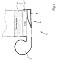
- Fig. 1
- eine schematische, geschnittene Darstellung einer erfindungsgemäßen Luftführungsvorrichtung für ein linksgelenktes Kraftfahrzeug,
- Fig. 2
- eine schematische, geschnittene Darstellung einer erfindungsgemäßen Luftführungsvorrichtung für ein rechtsgelenktes Kraftfahrzeug,
- Fig. 3
- eine schematische, geschnittene Darstellung einer herkömmlichen Luftführungsvorrichtung für ein linksgelenktes Kraftfahrzeug, und
- Fig. 4
- eine schematische, geschnittene Darstellung herkömmlichen Luftführungsvorrichtungen für ein links- und ein rechtsgelenktes Kraftfahrzeug in einer gemeinsamen Darstellung, wobei die Luftführungsvorrichtung für das rechtsgelenkte Kraftfahrzeug mit dünneren Linien dargestellt ist.
- Ein Luftführungsgehäuse 1, das auf Grund einer entsprechend ausgestalteten Luftführungsvorrichtung, auf die an späterer Stelle näher eingegangen wird, für links- und rechtsgelenkte Kraftfahrzeuge, verwendet werden kann, ist derart ausgebildet, dass am Luftführungsgehäuse 1 ein Gebläse 2 wahlweise, d.h. je nach Anordnung der Lenkung, links oder rechts angeflanscht werden kann. Hierfür sind im Luftführungsgehäuse 1 einander gegenüberliegende Gehäuseöffnungen vorgesehen. Dem Geläse 2 nachfolgend angeordnet ist ein Filter 3 und ein oder mehrere Wärmetauscher, vorliegend ein Verdampfer 4 und ein Heizer (nicht dargestellt), zur Klimatisierung der durchströmenden Luft vorgesehen.
- Im Umlenkbereich der Luftströmung nach dem Gebläse 2 und vor dem zur Filterung der Luft angeordneten Filter 3 ist zur Optimierung der Luftverteilung über die gesamte Filterfläche und somit zur möglichst gleichmäßigen Ausnutzung des Filters 3, wie auch zur gleichmäßigen Luftverteilung über den nachfolgenden Wärmetauscher, ein seitlich durch die dem Gebläse 2 gegenüberliegende Gehäuseöffnung ein mit einem entsprechend strömungstechnisch optimierten Profil versehener Filterdeckel 5 eingeschoben, welcher die Luftführungsvorrichtung 6 bildet.
- Der Filterdeckel 5 ist für seine Befestigung am Luftführungsgehäuse 1 entsprechend dem Gebläse 2 für die spiegelbildlich ausgebildete Variante ausgebildet, so dass keine zusätzlichen Vorrichtungen zur Befestigung am Luftführungsgehäuse 1 erforderlich sind, sondern das gleiche Luftführungsgehäuse 1 für beide Anordnungen der Lenkung verwendet werden kann. Ebenfalls ist bei der vorliegenden Symmetrie der Filterdeckel 5 für beide Anordnungen der Lenkung verwendbar, so dass links- und rechtsgelenkte Kraftfahrzeuge mit den gleichen Elementen ausgestattet werden können, wobei sich nur die Anordnung von Gebläse 2 und Filterdeckel 5 unterscheidet. Vorliegend hat der Filterdeckel 5 über seine gesamte Breite, d.h. in Blickrichtung von Fig. 1 bzw. 2 das gleiche Profil im Luftführungsbereich.
-
- 1
- Luftführungsgehäuse
- 2
- Gebläse
- 3
- Filter
- 4
- Verdampfer
- 5
- Filterdeckel
- 6
- Luftführungsvorrichtung
Claims (7)
- Heizungs-, Belüftungs- oder Klimaanlage mit einem Gebläse, gegebenenfalls einem Heizkörper und gegebenenfalls einem Verdampfer, mit einem Luftführungsgehäuse und mit einer Luftführungsvorrichtung, an dem ein Gebläse angeordnet ist, wobei die Luftführungsvorrichtung getrennt vom Luftführungsgehäuse ausgebildet ist, wobei sie durch eine Gehäuseöffnung in das Luftführungsgehäuse eingeschoben ist, dadurch gekennzeichnet, dass die Gehäuseöffnung einer weiteren Gehäuseöffnung gegenüberliegt, bei der das Gebläse angebracht ist.
- Heizungs-, Belüftungs- oder Klimaanlage nach Anspruch 1, dadurch gekennzeichnet, dass die Luftführungsvorrichtung durch einen Filterdeckel gebildet ist oder als Filterdeckel ausgebildet ist.
- Heizungs-, Belüftungs- oder Klimaanlage nach Anspruch 1 oder 2, dadurch gekennzeichnet, dass der Luftführungsvorrichtung in Luftströmungsrichtung gesehen nachgeordnet ein Filter angeordnet ist.
- Heizungs-, Belüftungs- oder Klimaanlage nach einem der vorhergehenden Ansprüche, dadurch gekennzeichnet, daß das Luftführungsgehäuse zumindest zwei gegenüberliegende Öffnungen aufweist, zur Aufnahme der Luftführungsvorrichtung bzw. zur Befestigung des Gebläses.
- Heizungs-, Belüftungs- oder Klimaanlage nach einem der vorhergehenden Ansprüche, dadurch gekennzeichnet, dass das Luftführungsgehäuse und die Luftführungsvorrichtung die gleichen Befestigungsvorrichtungen aufweist wie für ein Gebläse des beispielsweise andersseitig gelenkten Kraftfahrzeug-Typs.
- Heizungs-, Belüftungs- oder Klimaanlage nach einem der vorhergehenden Ansprüche, dadurch gekennzeichnet, dass das Luftführungsgehäuse oder die Luftführungsvorrichtung spiegelbildlich bezüglich der Mittelebene ausgebildet ist.
- Heizungs-, Belüftungs- oder Klimaanlage nach einem der vorhergehenden Ansprüche, dadurch gekennzeichnet, dass die Luftführungsvorrichtung über die gesamte Breite im Luftführungsbereich das gleiche Profil aufweist.
Priority Applications (4)
| Application Number | Priority Date | Filing Date | Title |
|---|---|---|---|
| AT04290057T ATE353784T1 (de) | 2004-01-08 | 2004-01-08 | Heizungs-, belüftungs- oder klimaanlage mit einer luftführungsvorrichtung |
| DE502004002901T DE502004002901D1 (de) | 2004-01-08 | 2004-01-08 | Heizungs-, Belüftungs- oder Klimaanlage mit einer Luftführungsvorrichtung |
| EP04290057A EP1552971B1 (de) | 2004-01-08 | 2004-01-08 | Heizungs-, Belüftungs- oder Klimaanlage mit einer Luftführungsvorrichtung |
| US11/031,347 US7147039B2 (en) | 2004-01-08 | 2005-01-10 | Air routing device for a motor vehicle air conditioning or heating system |
Applications Claiming Priority (1)
| Application Number | Priority Date | Filing Date | Title |
|---|---|---|---|
| EP04290057A EP1552971B1 (de) | 2004-01-08 | 2004-01-08 | Heizungs-, Belüftungs- oder Klimaanlage mit einer Luftführungsvorrichtung |
Publications (2)
| Publication Number | Publication Date |
|---|---|
| EP1552971A1 EP1552971A1 (de) | 2005-07-13 |
| EP1552971B1 true EP1552971B1 (de) | 2007-02-14 |
Family
ID=34586017
Family Applications (1)
| Application Number | Title | Priority Date | Filing Date |
|---|---|---|---|
| EP04290057A Expired - Lifetime EP1552971B1 (de) | 2004-01-08 | 2004-01-08 | Heizungs-, Belüftungs- oder Klimaanlage mit einer Luftführungsvorrichtung |
Country Status (4)
| Country | Link |
|---|---|
| US (1) | US7147039B2 (de) |
| EP (1) | EP1552971B1 (de) |
| AT (1) | ATE353784T1 (de) |
| DE (1) | DE502004002901D1 (de) |
Families Citing this family (3)
| Publication number | Priority date | Publication date | Assignee | Title |
|---|---|---|---|---|
| EP1820676A1 (de) * | 2006-02-17 | 2007-08-22 | DENSO THERMAL SYSTEMS S.p.A. | Modulare Wärmetauschanordnung für Kraftfahrzeuge und modulares System zum Herstellung unterschiedlicher Wärmetauschanordnungen |
| DE102009028522B4 (de) * | 2009-08-13 | 2017-05-11 | Hanon Systems | Kompakte Klimaanlage für ein Kraftfahrzeug |
| DE102020210330A1 (de) | 2020-08-13 | 2022-02-17 | Mahle International Gmbh | Luftführungsgehäuse einer Heizungs-, Belüftungs- oder Klimaanlage |
Family Cites Families (5)
| Publication number | Priority date | Publication date | Assignee | Title |
|---|---|---|---|---|
| GB2290864A (en) * | 1994-06-29 | 1996-01-10 | Fan Kuo Fu | Evaporator and filter assembly for a car air conditioner |
| DE19613345B4 (de) * | 1996-04-03 | 2004-09-30 | Behr Gmbh & Co. Kg | Heizungs- oder Klimaanlage für ein Kraftfahrzeug |
| JP3921795B2 (ja) * | 1998-03-31 | 2007-05-30 | 株式会社デンソー | 空調装置 |
| FR2789018B1 (fr) * | 1999-01-29 | 2002-02-01 | Valeo Climatisation | Dispositif de chauffage et/ou climatisation de vehicule automobile avec pulseur d'air lateral |
| DE10104907A1 (de) * | 2001-02-03 | 2002-08-08 | Behr Gmbh & Co | Klimagerät für ein Kraftfahrzeug |
-
2004
- 2004-01-08 EP EP04290057A patent/EP1552971B1/de not_active Expired - Lifetime
- 2004-01-08 AT AT04290057T patent/ATE353784T1/de not_active IP Right Cessation
- 2004-01-08 DE DE502004002901T patent/DE502004002901D1/de not_active Expired - Lifetime
-
2005
- 2005-01-10 US US11/031,347 patent/US7147039B2/en not_active Expired - Lifetime
Also Published As
| Publication number | Publication date |
|---|---|
| DE502004002901D1 (de) | 2007-03-29 |
| EP1552971A1 (de) | 2005-07-13 |
| US7147039B2 (en) | 2006-12-12 |
| ATE353784T1 (de) | 2007-03-15 |
| US20050170773A1 (en) | 2005-08-04 |
Similar Documents
| Publication | Publication Date | Title |
|---|---|---|
| EP0125562B1 (de) | Luftversorgungsvorrichtung für die Fahrerkabine eines Fahrzeuges | |
| EP0818338B1 (de) | Belüftungseinrichtung für eine Fahrzeugkabine und Filtergehäuse | |
| EP2347135B1 (de) | Gebläseeinrichtung für ein fahrzeug | |
| EP1228907B1 (de) | Klimagerät für ein Kraftfahrzeug | |
| DE3046336A1 (de) | Fahrzeug-klimaanlage | |
| DE19814581B4 (de) | Klimaanlage für ein Kraftfahrzeug | |
| DE69635030T2 (de) | Luftfilter und kraftwagen mit diesem filter | |
| EP1552971B1 (de) | Heizungs-, Belüftungs- oder Klimaanlage mit einer Luftführungsvorrichtung | |
| DE10256619B3 (de) | Klimagerät für Fahrzeuge | |
| DE102008052112B4 (de) | Klimatisierungsanordnung für einen Führerstand | |
| DE19540020A1 (de) | Baueinheit für ein Kraftfahrzeug | |
| DE3818666A1 (de) | Luftkanal fuer ein kraftfahrzeug | |
| EP1531068B1 (de) | Kraftfahrzeug-Klimaanlage | |
| DE10147113B4 (de) | Vorrichtung zum Temperieren und Belüften von Kraftfahrzeugen | |
| DE69112734T2 (de) | Gebläse für Heizungs- und/oder Klimaanlagen für Kraftfahrzeuge und Einrichtung ausgerüstet mit zwei solchen Gebläsen. | |
| EP0266767A2 (de) | Anordnung zur Frischluftzufuhr für die Belüftung und/oder Klimatisierung eines Personenkraftwagens | |
| EP1747108B1 (de) | System zur kraftfahrzeug-belüftung und/oder -temperierung | |
| EP1636056B1 (de) | Bauanordnung für eine klimaanlage | |
| DE102021101511B4 (de) | Elektrofahrzeug | |
| DE102008010182A1 (de) | Gehäuse für eine Gasfördereinrichtung | |
| DE19821683B4 (de) | Anordnung zur Kühlung eines in eine Fahrzeugkabine eingebauten elektronischen Geräts | |
| DE3333064A1 (de) | Von einem gehaeuse aufgenommenes heizungs- lueftungs- und/oder klimageraet | |
| DE102021102754A1 (de) | Klimatisierungseinrichtung für einen Kraftwagen sowie Kraftwagen | |
| EP1468850B1 (de) | Modular aufgebaute Heizungs- oder Klimaanlage | |
| DE102012108070A1 (de) | Klimaanlage für ein Kraftfahrzeug |
Legal Events
| Date | Code | Title | Description |
|---|---|---|---|
| PUAI | Public reference made under article 153(3) epc to a published international application that has entered the european phase |
Free format text: ORIGINAL CODE: 0009012 |
|
| AK | Designated contracting states |
Kind code of ref document: A1 Designated state(s): AT BE BG CH CY CZ DE DK EE ES FI FR GB GR HU IE IT LI LU MC NL PT RO SE SI SK TR |
|
| AX | Request for extension of the european patent |
Extension state: AL LT LV MK |
|
| RAP1 | Party data changed (applicant data changed or rights of an application transferred) |
Owner name: BEHR FRANCE ROUFFACH SAS |
|
| 17P | Request for examination filed |
Effective date: 20060113 |
|
| AKX | Designation fees paid |
Designated state(s): AT BE BG CH CY CZ DE DK EE ES FI FR GB GR HU IE IT LI LU MC NL PT RO SE SI SK TR |
|
| GRAP | Despatch of communication of intention to grant a patent |
Free format text: ORIGINAL CODE: EPIDOSNIGR1 |
|
| GRAC | Information related to communication of intention to grant a patent modified |
Free format text: ORIGINAL CODE: EPIDOSCIGR1 |
|
| RTI1 | Title (correction) |
Free format text: HEATING, VENTILATING OR COOLING DEVICE WITH AN AIR GUIDING ARRANGEMENT |
|
| GRAS | Grant fee paid |
Free format text: ORIGINAL CODE: EPIDOSNIGR3 |
|
| GRAA | (expected) grant |
Free format text: ORIGINAL CODE: 0009210 |
|
| AK | Designated contracting states |
Kind code of ref document: B1 Designated state(s): AT BE BG CH CY CZ DE DK EE ES FI FR GB GR HU IE IT LI LU MC NL PT RO SE SI SK TR |
|
| PG25 | Lapsed in a contracting state [announced via postgrant information from national office to epo] |
Ref country code: IE Free format text: LAPSE BECAUSE OF FAILURE TO SUBMIT A TRANSLATION OF THE DESCRIPTION OR TO PAY THE FEE WITHIN THE PRESCRIBED TIME-LIMIT Effective date: 20070214 Ref country code: FI Free format text: LAPSE BECAUSE OF FAILURE TO SUBMIT A TRANSLATION OF THE DESCRIPTION OR TO PAY THE FEE WITHIN THE PRESCRIBED TIME-LIMIT Effective date: 20070214 Ref country code: NL Free format text: LAPSE BECAUSE OF FAILURE TO SUBMIT A TRANSLATION OF THE DESCRIPTION OR TO PAY THE FEE WITHIN THE PRESCRIBED TIME-LIMIT Effective date: 20070214 Ref country code: SI Free format text: LAPSE BECAUSE OF FAILURE TO SUBMIT A TRANSLATION OF THE DESCRIPTION OR TO PAY THE FEE WITHIN THE PRESCRIBED TIME-LIMIT Effective date: 20070214 Ref country code: DK Free format text: LAPSE BECAUSE OF FAILURE TO SUBMIT A TRANSLATION OF THE DESCRIPTION OR TO PAY THE FEE WITHIN THE PRESCRIBED TIME-LIMIT Effective date: 20070214 |
|
| REG | Reference to a national code |
Ref country code: GB Ref legal event code: FG4D Free format text: NOT ENGLISH |
|
| REG | Reference to a national code |
Ref country code: CH Ref legal event code: EP |
|
| REF | Corresponds to: |
Ref document number: 502004002901 Country of ref document: DE Date of ref document: 20070329 Kind code of ref document: P |
|
| REG | Reference to a national code |
Ref country code: IE Ref legal event code: FG4D Free format text: LANGUAGE OF EP DOCUMENT: GERMAN |
|
| PG25 | Lapsed in a contracting state [announced via postgrant information from national office to epo] |
Ref country code: SE Free format text: LAPSE BECAUSE OF FAILURE TO SUBMIT A TRANSLATION OF THE DESCRIPTION OR TO PAY THE FEE WITHIN THE PRESCRIBED TIME-LIMIT Effective date: 20070514 |
|
| PG25 | Lapsed in a contracting state [announced via postgrant information from national office to epo] |
Ref country code: BG Free format text: LAPSE BECAUSE OF FAILURE TO SUBMIT A TRANSLATION OF THE DESCRIPTION OR TO PAY THE FEE WITHIN THE PRESCRIBED TIME-LIMIT Effective date: 20070515 |
|
| PG25 | Lapsed in a contracting state [announced via postgrant information from national office to epo] |
Ref country code: ES Free format text: LAPSE BECAUSE OF FAILURE TO SUBMIT A TRANSLATION OF THE DESCRIPTION OR TO PAY THE FEE WITHIN THE PRESCRIBED TIME-LIMIT Effective date: 20070525 |
|
| PG25 | Lapsed in a contracting state [announced via postgrant information from national office to epo] |
Ref country code: PT Free format text: LAPSE BECAUSE OF FAILURE TO SUBMIT A TRANSLATION OF THE DESCRIPTION OR TO PAY THE FEE WITHIN THE PRESCRIBED TIME-LIMIT Effective date: 20070716 |
|
| NLV1 | Nl: lapsed or annulled due to failure to fulfill the requirements of art. 29p and 29m of the patents act | ||
| ET | Fr: translation filed | ||
| GBV | Gb: ep patent (uk) treated as always having been void in accordance with gb section 77(7)/1977 [no translation filed] |
Effective date: 20070214 |
|
| REG | Reference to a national code |
Ref country code: IE Ref legal event code: FD4D |
|
| PG25 | Lapsed in a contracting state [announced via postgrant information from national office to epo] |
Ref country code: SK Free format text: LAPSE BECAUSE OF FAILURE TO SUBMIT A TRANSLATION OF THE DESCRIPTION OR TO PAY THE FEE WITHIN THE PRESCRIBED TIME-LIMIT Effective date: 20070214 Ref country code: GB Free format text: LAPSE BECAUSE OF FAILURE TO SUBMIT A TRANSLATION OF THE DESCRIPTION OR TO PAY THE FEE WITHIN THE PRESCRIBED TIME-LIMIT Effective date: 20070214 |
|
| PLBE | No opposition filed within time limit |
Free format text: ORIGINAL CODE: 0009261 |
|
| STAA | Information on the status of an ep patent application or granted ep patent |
Free format text: STATUS: NO OPPOSITION FILED WITHIN TIME LIMIT |
|
| PG25 | Lapsed in a contracting state [announced via postgrant information from national office to epo] |
Ref country code: RO Free format text: LAPSE BECAUSE OF FAILURE TO SUBMIT A TRANSLATION OF THE DESCRIPTION OR TO PAY THE FEE WITHIN THE PRESCRIBED TIME-LIMIT Effective date: 20070214 Ref country code: CZ Free format text: LAPSE BECAUSE OF FAILURE TO SUBMIT A TRANSLATION OF THE DESCRIPTION OR TO PAY THE FEE WITHIN THE PRESCRIBED TIME-LIMIT Effective date: 20070214 |
|
| 26N | No opposition filed |
Effective date: 20071115 |
|
| PG25 | Lapsed in a contracting state [announced via postgrant information from national office to epo] |
Ref country code: IT Free format text: LAPSE BECAUSE OF FAILURE TO SUBMIT A TRANSLATION OF THE DESCRIPTION OR TO PAY THE FEE WITHIN THE PRESCRIBED TIME-LIMIT Effective date: 20070214 Ref country code: GR Free format text: LAPSE BECAUSE OF FAILURE TO SUBMIT A TRANSLATION OF THE DESCRIPTION OR TO PAY THE FEE WITHIN THE PRESCRIBED TIME-LIMIT Effective date: 20070515 |
|
| BERE | Be: lapsed |
Owner name: BEHR FRANCE ROUFFACH SAS Effective date: 20080131 |
|
| PG25 | Lapsed in a contracting state [announced via postgrant information from national office to epo] |
Ref country code: MC Free format text: LAPSE BECAUSE OF NON-PAYMENT OF DUE FEES Effective date: 20080131 |
|
| REG | Reference to a national code |
Ref country code: CH Ref legal event code: PL |
|
| PG25 | Lapsed in a contracting state [announced via postgrant information from national office to epo] |
Ref country code: LI Free format text: LAPSE BECAUSE OF NON-PAYMENT OF DUE FEES Effective date: 20080131 Ref country code: CH Free format text: LAPSE BECAUSE OF NON-PAYMENT OF DUE FEES Effective date: 20080131 |
|
| PG25 | Lapsed in a contracting state [announced via postgrant information from national office to epo] |
Ref country code: EE Free format text: LAPSE BECAUSE OF FAILURE TO SUBMIT A TRANSLATION OF THE DESCRIPTION OR TO PAY THE FEE WITHIN THE PRESCRIBED TIME-LIMIT Effective date: 20070214 |
|
| PG25 | Lapsed in a contracting state [announced via postgrant information from national office to epo] |
Ref country code: BE Free format text: LAPSE BECAUSE OF NON-PAYMENT OF DUE FEES Effective date: 20080131 |
|
| PG25 | Lapsed in a contracting state [announced via postgrant information from national office to epo] |
Ref country code: AT Free format text: LAPSE BECAUSE OF NON-PAYMENT OF DUE FEES Effective date: 20080108 |
|
| PG25 | Lapsed in a contracting state [announced via postgrant information from national office to epo] |
Ref country code: CY Free format text: LAPSE BECAUSE OF FAILURE TO SUBMIT A TRANSLATION OF THE DESCRIPTION OR TO PAY THE FEE WITHIN THE PRESCRIBED TIME-LIMIT Effective date: 20070214 |
|
| PG25 | Lapsed in a contracting state [announced via postgrant information from national office to epo] |
Ref country code: HU Free format text: LAPSE BECAUSE OF FAILURE TO SUBMIT A TRANSLATION OF THE DESCRIPTION OR TO PAY THE FEE WITHIN THE PRESCRIBED TIME-LIMIT Effective date: 20070815 Ref country code: LU Free format text: LAPSE BECAUSE OF NON-PAYMENT OF DUE FEES Effective date: 20080108 |
|
| PG25 | Lapsed in a contracting state [announced via postgrant information from national office to epo] |
Ref country code: TR Free format text: LAPSE BECAUSE OF FAILURE TO SUBMIT A TRANSLATION OF THE DESCRIPTION OR TO PAY THE FEE WITHIN THE PRESCRIBED TIME-LIMIT Effective date: 20070214 |
|
| PGFP | Annual fee paid to national office [announced via postgrant information from national office to epo] |
Ref country code: FR Payment date: 20110209 Year of fee payment: 8 |
|
| PGFP | Annual fee paid to national office [announced via postgrant information from national office to epo] |
Ref country code: DE Payment date: 20120207 Year of fee payment: 9 |
|
| REG | Reference to a national code |
Ref country code: FR Ref legal event code: ST Effective date: 20120928 |
|
| PG25 | Lapsed in a contracting state [announced via postgrant information from national office to epo] |
Ref country code: FR Free format text: LAPSE BECAUSE OF NON-PAYMENT OF DUE FEES Effective date: 20120131 |
|
| PG25 | Lapsed in a contracting state [announced via postgrant information from national office to epo] |
Ref country code: DE Free format text: LAPSE BECAUSE OF NON-PAYMENT OF DUE FEES Effective date: 20130801 |
|
| REG | Reference to a national code |
Ref country code: DE Ref legal event code: R119 Ref document number: 502004002901 Country of ref document: DE Effective date: 20130801 |