EP1553034A2 - Method and device for controlling events synchronous with a running web - Google Patents
Method and device for controlling events synchronous with a running web Download PDFInfo
- Publication number
- EP1553034A2 EP1553034A2 EP05000156A EP05000156A EP1553034A2 EP 1553034 A2 EP1553034 A2 EP 1553034A2 EP 05000156 A EP05000156 A EP 05000156A EP 05000156 A EP05000156 A EP 05000156A EP 1553034 A2 EP1553034 A2 EP 1553034A2
- Authority
- EP
- European Patent Office
- Prior art keywords
- brand
- web
- signal
- pattern
- brightness
- Prior art date
- Legal status (The legal status is an assumption and is not a legal conclusion. Google has not performed a legal analysis and makes no representation as to the accuracy of the status listed.)
- Withdrawn
Links
Images
Classifications
-
- B—PERFORMING OPERATIONS; TRANSPORTING
- B65—CONVEYING; PACKING; STORING; HANDLING THIN OR FILAMENTARY MATERIAL
- B65H—HANDLING THIN OR FILAMENTARY MATERIAL, e.g. SHEETS, WEBS, CABLES
- B65H23/00—Registering, tensioning, smoothing or guiding webs
- B65H23/04—Registering, tensioning, smoothing or guiding webs longitudinally
- B65H23/18—Registering, tensioning, smoothing or guiding webs longitudinally by controlling or regulating the web-advancing mechanism, e.g. mechanism acting on the running web
- B65H23/188—Registering, tensioning, smoothing or guiding webs longitudinally by controlling or regulating the web-advancing mechanism, e.g. mechanism acting on the running web in connection with running-web
- B65H23/1882—Registering, tensioning, smoothing or guiding webs longitudinally by controlling or regulating the web-advancing mechanism, e.g. mechanism acting on the running web in connection with running-web and controlling longitudinal register of web
-
- B—PERFORMING OPERATIONS; TRANSPORTING
- B65—CONVEYING; PACKING; STORING; HANDLING THIN OR FILAMENTARY MATERIAL
- B65H—HANDLING THIN OR FILAMENTARY MATERIAL, e.g. SHEETS, WEBS, CABLES
- B65H2511/00—Dimensions; Position; Numbers; Identification; Occurrences
- B65H2511/50—Occurence
- B65H2511/51—Presence
- B65H2511/512—Marks, e.g. invisible to the human eye; Patterns
-
- B—PERFORMING OPERATIONS; TRANSPORTING
- B65—CONVEYING; PACKING; STORING; HANDLING THIN OR FILAMENTARY MATERIAL
- B65H—HANDLING THIN OR FILAMENTARY MATERIAL, e.g. SHEETS, WEBS, CABLES
- B65H2553/00—Sensing or detecting means
- B65H2553/40—Sensing or detecting means using optical, e.g. photographic, elements
- B65H2553/43—Bar code reader
Definitions
- the invention relates to a method and a device for Control of events synchronous to a moving Material web according to the preamble of claim 1 or claim 11.
- Such an event or series of Events that synchronize to a high accuracy moved material web to be controlled for example, an observation of a moving printing web represent by means of a video camera, in which the recorded Picture frozen by a flash lighting and is recorded. The moment of triggering the flash determines which image content has been captured on the camera is.
- Another improvement uses an ID code brand, which is recognized on the basis of its given pattern and can be used as a fixed point on the track. It will Although possible, the brand in an environment of print motifs However, the disadvantage remains that the brand must be relatively large in order to lateral Trajectories still to be found.
- the printing web On the material web, in particular the printing web, is of a printing cylinder periodically (usually per Cylinder revolution once) a trademark (code mark) printed using dashes and spaces different dimensions. Over the track, in the this mark pattern is printed is the invention Device arranged.
- the trade mark pattern becomes recorded in the subsequent evaluation process preferably a brand recognition for the connected Process reached quickly enough.
- This training is advantageous in that as the Influence of brightness fluctuations, for example caused by ambient light changes, as well as the Background to the signal formation is significantly reduced.
- the emergence of the output signals is practically a local differentiation of the gray value curve, by the only at the brightness transitions a signal peak formed becomes.
- About a threshold operation are preferably all Signals are cut below a defined level, so that only significant light / dark transitions be marked.
- the distances between the light / dark transitions are with the corresponding known distances from an ID code mark put into proportion and directly with a previously determined Ratio compared.
- the device according to the invention has a measuring head, with a lighting device, a cell sensor element, that is preferably a photodiode double line represents, in which both cells are parallel to each other and are arranged perpendicular to the direction of movement, a Calculator with a memory, which signals the two Evaluates photodiode lines at high speed and an output which, upon detection of a Match of current code and pattern a signal emits.
- a cell sensor element that is preferably a photodiode double line represents, in which both cells are parallel to each other and are arranged perpendicular to the direction of movement
- a Calculator with a memory, which signals the two Evaluates photodiode lines at high speed and an output which, upon detection of a Match of current code and pattern a signal emits.
- This signal is synchronous with high accuracy and can for controlling, for example, an image recording of a Video camera, to be used.
- the code mark is made of bars of alternating brightness (Alternatively, changing colors can be provided, the perceived as brightness change of the sensor array are) and is preferably a previously known Pattern of light / dark arrangements and thus transitions.
- the preferably provided beams lie in the web running direction seen one behind the other and thereby run when moving the Trace under the sensor array through.
- controller according to the method or the device according to the invention in a running web, which is also printed with other print motifs, permanent must be done is preferably a calculator structure provided, which performs the evaluation practically continuously and in the described application, the output signal with only very short delay, preferably less than 6 ⁇ s is.
- the arithmetic unit may preferably be constructed so that the comparison process is parallel for all sensor elements the sensor arrangement is executed and thus almost immediately, if a coincidence is reached in a lane, the Output signal is formed.
- the model can also be a calculator and a method chosen be in the recorded signals first cached and then processed sequentially.
- this can Process part be formed so that when parallel Reading out the lines immediately this difference value is formed and then proceed as described above.
- a further method step is inserted, accordingly the in signal formed in a preceding process step is further processed if it is below a defined Threshold is.
- Sensor element consisting of a number of individual sensors be used.
- a standard distance can be in the inventive method of Distance between at least two previous signals to be used.
- the standard distance is the distance between any two selected distances from the Signal sequence used.
- Illumination device preferably a constant light source be provided for adequate illumination of the Recording field provides.
- a LED lighting is used.
- a source consists of discrete ones Light-emitting surfaces.
- This training can be used others, the brightness distribution on the sensor affecting effects, e.g. the edge drop of an optic, to compensate.
- This can be done, for example happen that driving the luminescent diodes with according to different currents, so that individual diodes also shine differently strong and thus cause a non-homogeneous illumination on the measurement object, but their distribution is precisely designed so that they, superimposed with the edge drop of the lens, a uniform Signal generated on the sensor.
- the same can also be done be achieved that the arrangement of the light emitting elements in a different surface density (diodes each Area unit) or in a respectively adapted different distance from the measuring field.
- the passing object in particular the material web, becomes advantageously via an optical system on the sensor level displayed.
- the arrangement of the light source and the Sensor arrangement depends on which type of Underground (reflective, transparent, pronounced ...) the Trademark or Code mark has been and can be printed to serve different lighting principles, such as for example, a dark field illumination or a Bright field illumination.
- the calculator is integrated with the measuring head such that such a unit only needs a power supply as well an output line and possibly a bus interface to Communication needed.
- inventive method and the Device according to the invention a training, the Real-time recognition process.
- the device according to the invention preferably also has Sensor elements, which at an angle to the web running direction of> 0 ° are arranged.
- the angle between the web running direction and the sensor elements here at 90 °.
- the sensor cells in which the sensor elements are arranged, parallel are arranged.
- the sensor lines integrated in a sensor.
- the arithmetic unit is a freely programmable logic device (FPGA device), which includes all operations.
- FPGA device freely programmable logic device
- the individual sensor elements can in the inventive Device further consist of lines that are not more than 128 Include sensor elements.
- the exist Sensor elements themselves in turn from a number of Individual sensors.
- two CCD cells Charged Couple Devices
- the sensor elements can be a CMOS area sensor is provided, of which at least selected two lines are provided for evaluation.
- the device according to the invention can be constructed in this way be that the light-emitting elements individually so be controlled that the emitted light power through other assemblies or elements caused known compensated for local inhomogeneities.
- the arrangement of the light-emitting elements can Preferably, be chosen such that they by a different density in the arrangement by others Assemblies or elements caused known local Inhomogeneities compensated.
- the arrangement of the light-emitting elements so it is chosen by a different distance the light emitting elements of the illuminated surface is suitable, by other assemblies or elements caused known local inhomogeneities compensate.
- the lighting device may preferably have a Light stripes parallel to the arrangement of the sensor lines produce.
- a device for Signal preprocessing be arranged between the sensor arrangement and the calculating unit.
- the Signal processing devices of the invention Device a controller for controlling or regulating the Calculator, the lighting control device and the Has interfaces.
- the device 1 shown in the drawing has first a lighting device 1a, which in the particular preferred embodiment shown with a Lighting control 1b is connected.
- the Lighting device 1a is used to illuminate one measuring material web image area of a material web 10.
- the image area is in Example trap provided with a brand pattern 3 that off three arranged in the web running direction L one behind the other Brand elements 3a, 3b and 3c is constructed. in principle However, it would also be possible to have only two brand elements or to provide a greater number of these elements.
- the device 1 has a Signal processing device, which in the illustrated Embodiment an arithmetic unit 4a, an interface 7 and a Controller or a control / regulating device 9 has. Between the material web 10 and a sensor arrangement 2, the in the illustrated embodiment as a line sensor element is formed, an optic 5 is arranged. Between the Sensor assembly 2 and the calculator 4a is in the particular preferred embodiment according to the drawing a Device 4b arranged for signal preprocessing.
- the arithmetic unit 4a is also in mutual relationship with an output (trigger) 6 and the controller 9 coupled. Of the Controller 9 in turn is connected to the device 1b for Lighting control and the interface 7 coupled. Finally, the device 1 according to the invention has a Power supply 8 on.
- the one shown in the figure Embodiment of the device 1 according to the invention is used preferably for carrying out the initially described Method for controlling events synchronous to the moving web of material 10 by means of a comparison of on the Material web 10 located brand pattern 3 with a predetermined brand pattern.
Landscapes
- Length Measuring Devices By Optical Means (AREA)
- Inking, Control Or Cleaning Of Printing Machines (AREA)
- Accessory Devices And Overall Control Thereof (AREA)
- Controlling Sheets Or Webs (AREA)
Abstract
Description
Die Erfindung betrifft ein Verfahren und eine Vorrichtung zur Steuerung von Ereignissen synchron zu einer bewegten Materialbahn entsprechend dem Oberbegriff des Anspruches 1 bzw. des Anspruches 11.The invention relates to a method and a device for Control of events synchronous to a moving Material web according to the preamble of claim 1 or claim 11.
Ein derartiges Ereignis oder eine derartige Reihe von Ereignissen, die mit hoher Genauigkeit synchron zu einer bewegten Materialbahn gesteuert werden sollen, kann beispielsweise eine Beobachtung einer bewegten Druckbahn mittels einer Videokamera darstellen, bei der das aufgenommene Bild durch eine Blitzlichtbeleuchtung eingefroren und aufgenommen wird. Der Moment der Auslösung des Blitzlichtes bestimmt, welcher Bildinhalt auf der Kamera erfasst worden ist.Such an event or series of Events that synchronize to a high accuracy moved material web to be controlled for example, an observation of a moving printing web represent by means of a video camera, in which the recorded Picture frozen by a flash lighting and is recorded. The moment of triggering the flash determines which image content has been captured on the camera is.
Um einen genau definierten Punkt auf der Druckbahn treffen zu können, muss ein Hilfsmittel installiert sein, das einen Bezug zu einem Punkt der Druckbahn herstellt.To hit a well-defined point on the web You must have a resource installed that has a reference to a point of the printing line manufactures.
Üblicherweise werden Bahnen durch Walzen transportiert, sodass diese Walzen als Ausgangspunkt eine Zuordnung zu einem bestimmten Ort der Materialbahn erlauben. Im Falle einer Applikation in einer Druckmaschine oder einer Maschine, die ein durch Druck hergestelltes Muster verarbeitet, stellt insbesondere die Druckform einen sehr guten Bezug zum gedruckten Motiv dar. Dies wird üblicherweise ausgenutzt, indem an einem solchen Zylinder ein Drehgeber angebaut wird, dessen Impulse einen guten Bezug zur Bahn aufweisen.Usually, webs are transported by rollers, so these rollers as a starting point an assignment to a allow specific location of the material web. In case of a Application in a printing machine or a machine that Processes a pattern produced by printing especially the printing form a very good reference to printed motif. This is usually exploited, by fitting a rotary encoder to such a cylinder, whose pulses have a good relation to the web.
Nachteilig hierbei ist, dass durch Schlupf und Dehnung der Materialbahn sich dieser Bezug verschiebt und damit das Ziel der punktgenauen Triggerung nicht mehr erreicht wird. The disadvantage here is that by slippage and elongation of Material web moves this relation and thus the goal the pinpoint triggering is no longer achieved.
Eine Verbesserung dieser Situation kann dadurch erreicht werden, dass eine Blockmarke mitgedruckt wird, die dann zur Synchronisation mittels eines üblichen punktförmig abtastenden Lichttasters abgetastet wird. Nachteilig an dieser verbesserten Lösung ist jedoch, dass diese Marke eine beachtliche Größe (insbesondere Breite) aufweisen muss, um auch bei seitlichen Bahnlaufschwankungen noch sicher erkannt werden zu können. Der Druck einer solchen Marke erfordert einen zusätzlichen Materialaufwand an Papier, auf dem die Marke angeordnet ist.An improvement of this situation can be achieved be that a block mark is printed, which then to Synchronization by means of a conventional punctiform scanning Scanned light button. A disadvantage of this improved solution, however, is that this brand is a considerable size (especially width) must have to Even with lateral web run fluctuations still reliably recognized to be able to. The pressure of such a brand requires an additional cost of paper, on which the Brand is arranged.
Eine weitere Verbesserung bedient sich einer ID-Code-Marke, die aufgrund ihres vorgegebenen Musters wiedererkannt wird und als Fixpunkt auf der Bahn verwendet werden kann. Damit wird es zwar möglich, die Marke an einer Umgebung von Druckmotiven unterzubringen, allerdings bleibt der Nachteil, dass die Marke relativ groß ausgebildet sein muss, um bei seitlichen Bahnverläufen noch gefunden zu werden.Another improvement uses an ID code brand, which is recognized on the basis of its given pattern and can be used as a fixed point on the track. It will Although possible, the brand in an environment of print motifs However, the disadvantage remains that the brand must be relatively large in order to lateral Trajectories still to be found.
Bei der Verwendung von kameraähnlich arbeitender Sensorik ist es erforderlich, das gesamte Bild mit einer Aufnahme zu erfassen. Dies führt dazu, dass für längere Codes entweder mehrere Bilder aufgenommen und verarbeitet werden müssen oder über eine Zoom-Funktion jeweils eine Anpassung erfolgen muss, was wiederum zu erheblichen Kosten führt.When using camera-like working sensors is It requires the entire image with a shot too to capture. This leads to longer codes for either several pictures have to be taken and processed or an adjustment must be made via a zoom function, which in turn leads to considerable costs.
Es ist daher Aufgabe der vorliegenden Erfindung, ein Verfahren und eine Vorrichtung zur Steuerung von Ereignissen synchron zu einer bewegten Materialbahn entsprechend dem Oberbegriff des Anspruches 1 bzw. des Anspruches 11 zu schaffen, die es ermöglicht, eine Steuerung mit hoher Genauigkeit bei vergleichsweise geringem Aufwand durchzuführen.It is therefore an object of the present invention, a method and a device for controlling events synchronous to a moving material web according to the preamble of Claim 1 or claim 11 to provide it allows to provide a controller with high accuracy To carry out comparatively little effort.
Die Lösung dieser Aufgabe erfolgt durch die Merkmale des Anspruches 1 bzw. des Anspruches 11. Die Unteransprüche 2 bis 9 haben vorteilhafte Weiterbildungen des erfindungsgemäßen Verfahrens und die Unteransprüche 12 bis 14 haben vorteilhafte Weiterbildungen der erfindungsgemäßen Vorrichtung zu Inhalt.The solution to this problem is provided by the features of Claim 1 or claim 11. The dependent claims 2 to 9 have advantageous developments of the invention Method and subclaims 12 to 14 have advantageous Further developments of the device according to the invention to content.
Gemäß den Prinzipien vorliegender Erfindung wird ein neuartiges Verfahren und eine neuartige Vorrichtung zur Aufnahme und Auswertung von Signalen geschaffen, die von einer vorzugsweise kleinen Marke stammen und vorzugsweise mit einer festen Brennweite und konstanten Abbildungseigenschaften aufgenommen werden können.According to the principles of the present invention is a novel method and a novel device for Recording and evaluation of signals created by a preferably come from a small brand and preferably with a fixed focal length and constant imaging characteristics can be included.
Auf der Materialbahn, insbesondere der Druckbahn, wird von einem Druckzylinder periodisch (in der Regel pro Zylinderumdrehung ein Mal) ein Markenmuster (Code-Marke) gedruckt, das aus Strichen und Zwischenräumen mit unterschiedlichen Dimensionen besteht. Über der Spur, in der dieses Markenmuster gedruckt wird, ist die erfindungsgemäße Vorrichtung angeordnet.On the material web, in particular the printing web, is of a printing cylinder periodically (usually per Cylinder revolution once) a trademark (code mark) printed using dashes and spaces different dimensions. Over the track, in the this mark pattern is printed is the invention Device arranged.
Gemäß dem erfindungsgemäßen Verfahren wird das Markenmuster erfasst und im anschließenden Auswerteverfahren wird vorzugsweise eine Markenerkennung für den angeschlossenen Prozess ausreichend schnell erreicht.According to the method of the invention, the trade mark pattern becomes recorded in the subsequent evaluation process preferably a brand recognition for the connected Process reached quickly enough.
Dies erfolgt vorzugsweise durch Verwendung einer entsprechenden Sensoreinrichtung mit zumindest zwei Zellen, die in einem sehr kurzen Abstand hintereinander angeordnet sind, wobei jeweils ein Helligkeits-Differenzsignal zwischen zwei hintereinander liegenden Sensorelementen der einen und anderen Zeile gebildet wird.This is preferably done by using a corresponding sensor device with at least two cells, arranged in a very short distance one behind the other are, each having a brightness difference signal between two successive sensor elements of the one and other line is formed.
Diese Ausbildung ist insofern vorteilhaft, als damit der Einfluss von Helligkeitsschwankungen, beispielsweise hervorgerufen durch Umgebungslichtänderungen, sowie des Untergrundes auf die Signalbildung erheblich verringert wird. This training is advantageous in that as the Influence of brightness fluctuations, for example caused by ambient light changes, as well as the Background to the signal formation is significantly reduced.
Das Entstehen der Ausgangssignale stellt praktisch eine örtliche Differenzierung des Grauwertverlaufes dar, durch die nur noch an den Helligkeitsübergängen ein Signal-Peak gebildet wird. Über eine Schwellwertoperation werden vorzugsweise alle Signale unterhalb eines definierten Pegels abgeschnitten, sodass nur noch signifikante Hell-/Dunkel-Übergänge gekennzeichnet werden.The emergence of the output signals is practically a local differentiation of the gray value curve, by the only at the brightness transitions a signal peak formed becomes. About a threshold operation are preferably all Signals are cut below a defined level, so that only significant light / dark transitions be marked.
Die Abstände zwischen den Hell-/Dunkel-Übergängen werden mit den entsprechenden bekannten Abständen aus einer ID-Code-Marke ins Verhältnis gesetzt und direkt mit einem zuvor ermittelten Verhältnis verglichen.The distances between the light / dark transitions are with the corresponding known distances from an ID code mark put into proportion and directly with a previously determined Ratio compared.
Durch die Anzahl der nutzbaren Hell-/Dunkel-Übergänge, die aus der ID-Code-Marke resultieren, entsteht auf diese Weise eine Folge von Verhältnissen, die bei Gleichheit den Muster-Code repräsentieren. Bei ausreichender Übereinstimmung wird dann ein Ausgangssignal ausgelöst. Diese Ausgangssignalbildung erfolgt dann, wenn durch mindestens eine Paarung von Sensoren das gesuchte Muster erkannt worden ist.By the number of usable light / dark transitions that out resulting in the ID code mark, this creates one Consequence of relationships that, if equal, the pattern code represent. If there is sufficient agreement then an output signal is triggered. This output signal formation occurs when through at least one pair of sensors the wanted pattern has been recognized.
Bei einer besonders bevorzugten Ausführungsform der erfindungsgemäßen Vorrichtung weist diese einen Messkopf auf, der mit einer Beleuchtungseinrichtung, einem Zellen-Sensorelement, das vorzugsweise eine Photodioden-Doppelzeile darstellt, bei der beide Zellen zueinander parallel und senkrecht zur Bewegungsrichtung angeordnet sind, einem Rechenwerk mit einem Speicher, der die Signale der beiden Photodiodenzeilen mit hoher Geschwindigkeit auswertet und einem Ausgang versehen ist, der bei Feststellung einer Übereinstimmung von aktuellem Code und Muster ein Signal abgibt.In a particularly preferred embodiment of the The device according to the invention has a measuring head, with a lighting device, a cell sensor element, that is preferably a photodiode double line represents, in which both cells are parallel to each other and are arranged perpendicular to the direction of movement, a Calculator with a memory, which signals the two Evaluates photodiode lines at high speed and an output which, upon detection of a Match of current code and pattern a signal emits.
Dieses Signal ist mit hoher Genauigkeit bahnsynchron und kann zur Steuerung, beispielsweise einer Bildaufnahme einer Videokamera, verwendet werden. This signal is synchronous with high accuracy and can for controlling, for example, an image recording of a Video camera, to be used.
Die Code-Marke ist aus Balken von wechselnder Helligkeit (alternativ können auch wechselnde Farben vorgesehen sein, die als Helligkeitsänderung von der Sensoranordnung wahrgenommen werden) aufgebaut und ist vorzugsweise ein vorher bekanntes Muster von Hell-/Dunkel-Anordnungen und damit -Übergängen. Die vorzugsweise vorgesehenen Balken liegen in Bahnlaufrichtung gesehen hintereinander und laufen dadurch bei Bewegung der Bahn unter der Sensoranordnung hindurch.The code mark is made of bars of alternating brightness (Alternatively, changing colors can be provided, the perceived as brightness change of the sensor array are) and is preferably a previously known Pattern of light / dark arrangements and thus transitions. The preferably provided beams lie in the web running direction seen one behind the other and thereby run when moving the Trace under the sensor array through.
Dementsprechend erzeugen sie in den Sensorelementen, die sie passieren, jeweils eine Helligkeitsänderung.Accordingly, they generate in the sensor elements that they happen, each a brightness change.
Da die Steuerung gemäß dem erfindungsgemäßen Verfahren bzw. der erfindungsgemäßen Vorrichtung bei einer laufenden Bahn, die auch mit anderen Druckmotiven bedruckt ist, permanent erfolgen muss, ist vorzugsweise eine Rechenwerkstruktur vorgesehen, die die Auswertung praktisch fortlaufend erledigt und bei der beschriebenen Anwendung das Ausgangssignal mit nur sehr kurzer Verzögerung abgibt, die vorzugsweise weniger als 6 µs beträgt.Since the controller according to the method or the device according to the invention in a running web, which is also printed with other print motifs, permanent must be done, is preferably a calculator structure provided, which performs the evaluation practically continuously and in the described application, the output signal with only very short delay, preferably less than 6 μs is.
Hierzu kann das Rechenwerk vorzugsweise so aufgebaut sein, dass der Vergleichsprozess parallel für alle Sensorelemente der Sensoranordnung ausgeführt wird und damit nahezu sofort, wenn in einer Spur eine Koinzidenz erreicht ist, das Ausgangssignal gebildet wird.For this purpose, the arithmetic unit may preferably be constructed so that the comparison process is parallel for all sensor elements the sensor arrangement is executed and thus almost immediately, if a coincidence is reached in a lane, the Output signal is formed.
Für geringere Anforderungen an Verzögerung bis zur Erkennung des Musters kann auch ein Rechenwerk und ein Verfahren gewählt werden, in dem aufgenommene Signale zunächst zwischengespeichert und dann nacheinander abgearbeitet werden. Bei Verwendung von CCD-Zeilensensoren kann dieser Verfahrensteil so ausgebildet werden, dass beim parallelen Auslesen der Zeilen sofort dieser Differenzwert gebildet und dann, wie oben beschrieben, weiter verfahren wird. For lower delay requirements until detection The model can also be a calculator and a method chosen be in the recorded signals first cached and then processed sequentially. When using CCD line sensors this can Process part be formed so that when parallel Reading out the lines immediately this difference value is formed and then proceed as described above.
Gleichermaßen kann mit einer gemischten Arbeitsweise eine begrenzte Parallelverarbeitung mit Zwischenspeicherung von Teilbereichen aus den Zeilen gearbeitet werden, wenn die akzeptierte Verzögerungszeit dies erlaubt.Similarly, with a mixed mode of operation one can limited parallel processing with caching of Subareas are worked out of the lines when the accepted delay time allows this.
Vorzugsweise ist bei dem erfindungsgemäßen Verfahren ferner ein weiterer Verfahrensschritt eingefügt, demgemäß das in einem vorhergehenden Verfahrensschritt gebildete Signal nicht weiterverarbeitet wird, falls es unterhalb einer definierten Schwelle liegt.Preferably, in the method according to the invention further a further method step is inserted, accordingly the in signal formed in a preceding process step is further processed if it is below a defined Threshold is.
Bevorzugterweise kann bei dem Verfahren der Erfindung ein Sensorelement, bestehend aus einer Anzahl von Einzelsensoren verwendet werden.Preferably, in the method of the invention Sensor element consisting of a number of individual sensors be used.
Als Normabstand kann bei dem erfindungsgemäßen Verfahren der Abstand zwischen zumindestens zwei vorausgegangenen Signalen benutzt werden. Vorzugsweise wird als Normabstand der Abstand zwischen zwei beliebig ausgewählten Abständen aus der Signalfolge verwendet.As a standard distance can be in the inventive method of Distance between at least two previous signals to be used. Preferably, the standard distance is the distance between any two selected distances from the Signal sequence used.
Alternativ ist es möglich, den Normabstand aus einer von einem bahnsynchron angetriebenen Impulsgeber stammenden Impulsfolge zu bilden.Alternatively, it is possible to change the standard distance from one of a track synchronous driven pulse originating pulse train to build.
Als weitere Alternative ist es möglich, dass der Normabstand aus der an sich bekannten Bewegungsgeschwindigkeit der Materialbahn und der an sich bekannten geometrischen Länge des Code-Musters rechnerisch ermittelt wird.As another alternative, it is possible that the standard distance from the known movement speed of the Material web and the known geometric length of the Code pattern is calculated.
Bei der erfindungsgemäßen Vorrichtung kann als Beleuchtungseinrichtung vorzugsweise eine Konstant-Lichtquelle vorgesehen sein, die für eine ausreichende Ausleuchtung des Aufnahmefeldes sorgt. In the apparatus according to the invention can as Illumination device preferably a constant light source be provided for adequate illumination of the Recording field provides.
Eine andere vorteilhafte Ausbildung der Beleuchtungseinrichtung besteht darin, dass eine LED-Beleuchtung verwendet wird. Eine solche Quelle besteht aus diskreten Lichtemissionsflächen. Diese Ausbildung kann dazu benutzt werden, andere, die Helligkeitsverteilung auf dem Sensor beeinflussende Effekte, wie z.B. den Randabfall einer Optik, zu kompensieren. Dies wiederum kann beispielsweise dadurch geschehen, dass die Ansteuerung der Luminiszensdioden mit entsprechend unterschiedlichen Strömen erfolgt, sodass einzelne Dioden auch unterschiedlich stark leuchten und damit eine nichthomogene Beleuchtung auf dem Messobjekt hervorrufen, deren Verteilung aber genau so ausgebildet ist, dass sie, überlagert mit dem Randabfall des Objektivs, ein gleichmäßiges Signal auf dem Sensor erzeugt. Gleiches kann auch dadurch erreicht werden, dass die Anordnung der Lichtemissionselemente in einer unterschiedlichen Flächendichte (Dioden je Flächeneinheit) erfolgt oder in einem jeweils angepassten unterschiedlichen Abstand vom Messfeld.Another advantageous embodiment of the lighting device is that a LED lighting is used. Such a source consists of discrete ones Light-emitting surfaces. This training can be used others, the brightness distribution on the sensor affecting effects, e.g. the edge drop of an optic, to compensate. This, in turn, can be done, for example happen that driving the luminescent diodes with according to different currents, so that individual diodes also shine differently strong and thus cause a non-homogeneous illumination on the measurement object, but their distribution is precisely designed so that they, superimposed with the edge drop of the lens, a uniform Signal generated on the sensor. The same can also be done be achieved that the arrangement of the light emitting elements in a different surface density (diodes each Area unit) or in a respectively adapted different distance from the measuring field.
Das vorbeilaufende Objekt, insbesondere die Materialbahn, wird vorteilhafter Weise über eine Optik auf die Sensorebene abgebildet. Die Anordnung der Lichtquelle und der Sensoranordnung hängt dabei davon ab, auf welche Art von Untergrund (reflektierend, durchsichtig, remittierend ...) die Markenmuster bzw. Code-Marke gedruckt worden ist und kann sich dazu unterschiedlicher Beleuchtungsprizipien bedienen, wie beispielsweise einer Dunkelfeldbeleuchtung oder einer Hellfeldbeleuchtung.The passing object, in particular the material web, becomes advantageously via an optical system on the sensor level displayed. The arrangement of the light source and the Sensor arrangement depends on which type of Underground (reflective, transparent, reminiscent ...) the Trademark or Code mark has been and can be printed to serve different lighting principles, such as for example, a dark field illumination or a Bright field illumination.
Eine besonders vorteilhafte Weiterbildung ist gegeben, wenn das Rechenwerk mit dem Messkopf derart integriert ist, dass eine solche Einheit nur noch eine Spannungsversorgung sowie eine Ausgangsleitung und ggf. ein Bus-Interface zur Kommunikation benötigt. A particularly advantageous development is given if the calculator is integrated with the measuring head such that such a unit only needs a power supply as well an output line and possibly a bus interface to Communication needed.
Bei der zuvor beschriebenen, besonders bevorzugten Ausführungsform kann beispielsweise über ein integriertes BusSystem das zu detektierende Markenmuster von einem anderen externen Rechnersystem, dass ebenfalls mit einem gleichen Bus-Interface ausgerüstet ist, übertragen werden. Damit wird es möglich, situationsangepasste, unterschiedliche Codes mit dem System zu erkennen.In the previously described, particularly preferred Embodiment, for example, via an integrated bus system the brand pattern to be detected by another external computer system, which also has a same bus interface equipped to be transmitted. It will possible, situation-adapted, different codes with the System to recognize.
Mit dem zuvor beschriebenen erfindungsgemäßen Verfahren und der erfindungsgemäßen Vorrichtung ist es grundsätzlich auch möglich, beliebig lange Codes auszuwerten, ohne dass ein Code vollständig und gleichzeitig erfasst werden muss.With the previously described inventive method and The device according to the invention is in principle also possible to evaluate arbitrarily long codes without a code must be recorded completely and simultaneously.
Ferner ist es erfindungsgemäß möglich, im Vergleich zu üblichen Techniken kleinere ID-Code-Marken bzw. Markenmuster zu erkennen, auch wenn das Objektiv durch verfahrensbedingte seitliche Bewegungen einen Sensor an unterschiedlicher Stelle passiert. Störeffekte bei der Erkennung, hervorgerufen durch Beleuchtungsschwankungen oder Schwankungen im Untergrund, können mit dem erfindungsgemäßen Verfahren weitgehend aus der Messwertgewinnung eliminiert werden, sodass die Arbeitsweise gegenüber herkömmlichen reinen Grauwert basierenden Verfahren deutlich verbessert werden kann. Gegen ein Flattern der Materialbahn, dass sich sowohl in Helligkeitsschwankungen, als auch Abbildungsgrößenänderungen äußert, ist das erfindungsgemäße Verfahren weitgehend unempfindlich.Furthermore, it is possible according to the invention, in comparison to usual techniques smaller ID code brands or brand designs to recognize, even if the lens by procedural lateral movements a sensor at different location happens. Disturbing effects on detection, caused by Lighting fluctuations or fluctuations in the subsurface, can with the inventive method largely from the Measurement results are eliminated, so the way of working compared to conventional pure gray scale based methods can be significantly improved. Against a flutter of the Material web, resulting in both brightness variations, as also expresses picture size changes, that is Inventive method largely insensitive.
Ferner ermöglichen das erfindungsgemäße Verfahren und die erfindungsgemäße Vorrichtung eine Ausbildung, die den Erkennungsvorgang in Echtzeit leisten können.Furthermore, the inventive method and the Device according to the invention a training, the Real-time recognition process.
Die erfindungsgemäße Vorrichtung weist ferner vorzugsweise Sensorelemente auf, die in einem Winkel zur Bahnlaufrichtung von > 0° angeordnet sind. The device according to the invention preferably also has Sensor elements, which at an angle to the web running direction of> 0 ° are arranged.
Bevorzugterweise ist der Winkel zwischen Bahnlaufrichtung und den Sensorelementen hier bei 90°.Preferably, the angle between the web running direction and the sensor elements here at 90 °.
Ferner ist es erfindungsgemäß möglich, dass die Sensorzellen, in denen die Sensorelemente angeordnet sind, parallel angeordnet sind.Furthermore, it is possible according to the invention that the sensor cells, in which the sensor elements are arranged, parallel are arranged.
Ferner ist es bevorzugterweise möglich, dass die Sensorzeilen in einem Sensor integriert sind.Furthermore, it is preferably possible that the sensor lines integrated in a sensor.
Bevorzugterweise ist es ferner möglich, ein Interface vorzusehen, das die vorgegebene Impulsfolge einem Rechenwerk übermittelt. Bevorzugterweise ist das Rechenwerk aus einem frei programmierbaren Logikbaustein (FPGA-Baustein) aufgebaut, der alle Operationen beinhaltet.Preferably, it is also possible to have an interface provide that the predetermined pulse train an arithmetic unit transmitted. Preferably, the arithmetic unit is a freely programmable logic device (FPGA device), which includes all operations.
Die einzelnen Sensorelemente können bei der erfindungsgemäßen Vorrichtung ferner aus Zeilen bestehen, die nicht mehr als 128 Sensorelemente beinhalten. Bevorzugterweise bestehen die Sensorelemente selbst wiederum aus einer Anzahl von Einzelsensoren. Bevorzugterweise können als Sensorelemente zwei CCD-Zellen (Charged Couple Devices) vorgesehen sein.The individual sensor elements can in the inventive Device further consist of lines that are not more than 128 Include sensor elements. Preferably, the exist Sensor elements themselves in turn from a number of Individual sensors. Preferably, as sensor elements two CCD cells (Charged Couple Devices) may be provided.
Alternativ ist es möglich, dass als Sensorelemente eine CMOS-Flächensensor vorgesehen ist, von dem mindestens selektierte zwei Zeilen zur Auswertung vorgesehen sind.Alternatively, it is possible for the sensor elements to be a CMOS area sensor is provided, of which at least selected two lines are provided for evaluation.
Bei einer weiteren bevorzugten Ausführungsform ist in das Sensorelement für jeweils zwei Zeilen eine an sich bekannte Hardware-Struktur integriert.In a further preferred embodiment is in the Sensor element for each two lines a known per se Hardware structure integrated.
Ferner kann die erfindungsgemäße Vorrichtung so aufgebaut sein, dass die lichtemittierenden Elemente einzeln so angesteuert werden, dass die emittierte Lichtleistung durch andere Baugruppen oder Elemente hervorgerufene bekannte örtliche Inhomogenitäten kompensiert. Furthermore, the device according to the invention can be constructed in this way be that the light-emitting elements individually so be controlled that the emitted light power through other assemblies or elements caused known compensated for local inhomogeneities.
Die Anordnung der lichtemittierenden Elemente kann bevorzugterweise derart gewählt werden, dass sie durch eine unterschiedliche Dichte in der Anordnung durch andere Baugruppen oder Elemente hervorgerufene bekannte örtliche Inhomogenitäten kompensiert.The arrangement of the light-emitting elements can Preferably, be chosen such that they by a different density in the arrangement by others Assemblies or elements caused known local Inhomogeneities compensated.
Bei einer weiteren bevorzugten Ausführungsform kann vorgesehen sein, dass die Anordnung der lichtemittierenden Elemente so gewählt ist, dass sie durch einen unterschiedlichen Abstand der lichtemittierenden Elemente von der beleuchteten Fläche geeignet ist, durch andere Baugruppen oder Elemente hervorgerufene bekannte örtliche Inhomogenitäten zu kompensieren.In a further preferred embodiment can be provided be that the arrangement of the light-emitting elements so it is chosen by a different distance the light emitting elements of the illuminated surface is suitable, by other assemblies or elements caused known local inhomogeneities compensate.
Die Beleuchtungseinrichtung kann vorzugsweise einen Lichtstreifen parallel zur Anordnung der Sensorzeilen erzeugen.The lighting device may preferably have a Light stripes parallel to the arrangement of the sensor lines produce.
Ferner ist es möglich, dass zwischen der Sensoranordnung und der Materialbahn eine Optikanordnung vorgesehen ist.Furthermore, it is possible that between the sensor arrangement and the material web is provided an optical arrangement.
Bei einer weiteren bevorzugten Ausführungsform kann zwischen der Sensoranordnung und dem Rechenwerk eine Einrichtung zur Signalvorverarbeitung angeordnet sein.In a further preferred embodiment, between the sensor arrangement and the calculating unit, a device for Signal preprocessing be arranged.
Schließlich ist es grundsätzlich denkbar, dass die Signalverarbeitungseinrichtungen der erfindungsgemäßen Vorrichtung einen Controller zur Steuerung bzw. Regelung des Rechenwerks, der Beleuchtungssteuerungseinrichtung und des Interfaces aufweist.Finally, it is basically conceivable that the Signal processing devices of the invention Device a controller for controlling or regulating the Calculator, the lighting control device and the Has interfaces.
Weitere Einzelheiten, Merkmale und Vorteile der Erfindung ergeben sich aus nachfolgender Beschreibung eines Ausführungsbeispiels. Further details, features and advantages of the invention result from the following description of a Embodiment.
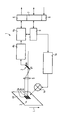
Die einzige Figur der Zeichnung zeigt eine schematisch stark vereinfachte Blockdarstellung einer erfindungsgemäßen Vorrichtung.The sole figure of the drawing shows a schematic strong simplified block diagram of an inventive Contraption.
Die in der Zeichnung dargestellte Vorrichtung 1 weist zunächst eine Beleuchtungseinrichtung 1a auf, die bei der besonders bevorzugten dargestellten Ausführungsform mit einer Beleuchtungssteuerung 1b verbunden ist. Die Beleuchtungseinrichtung 1a dient zur Beleuchtung eines zu vermessenden Materialbahnbildbereiches einer Materialbahn 10. Wie die Figur verdeutlicht, ist der Bildbereich im Beispielsfalle mit einem Markenmuster 3 versehen, dass aus drei in Bahnlaufrichtung L hintereinander angeordneten Markenelementen 3a, 3b und 3c aufgebaut ist. Grundsätzlich wäre es jedoch auch möglich, lediglich zwei Markenelemente oder eine größere Anzahl dieser Elemente vorzusehen.The device 1 shown in the drawing has first a lighting device 1a, which in the particular preferred embodiment shown with a Lighting control 1b is connected. The Lighting device 1a is used to illuminate one measuring material web image area of a material web 10. As the figure illustrates, the image area is in Example trap provided with a brand pattern 3 that off three arranged in the web running direction L one behind the other Brand elements 3a, 3b and 3c is constructed. in principle However, it would also be possible to have only two brand elements or to provide a greater number of these elements.
Ferner weist die erfindungsgemäße Vorrichtung 1 eine
Signalverarbeitungseinrichtung auf, die bei der dargestellten
Ausführungsform ein Rechenwerk 4a, ein Interface 7 sowie einen
Controller bzw. eine Steuer-/Regeleinrichtung 9 aufweist.
Zwischen der Materialbahn 10 und einer Sensoranordnung 2, die
bei der dargestellten Ausführungsform als Zeilensensorelement
ausgebildet ist, ist eine Optik 5 angeordnet. Zwischen der
Sensoranordnung 2 und dem Rechenwerk 4a ist bei der besonders
bevorzugten Ausführungsform gemäß der Zeichnung eine
Einrichtung 4b zur Signalvorverarbeitung angeordnet.Furthermore, the device 1 according to the invention has a
Signal processing device, which in the illustrated
Embodiment an arithmetic unit 4a, an interface 7 and a
Controller or a control / regulating device 9 has.
Between the material web 10 and a sensor arrangement 2, the
in the illustrated embodiment as a line sensor element
is formed, an optic 5 is arranged. Between the
Sensor assembly 2 and the calculator 4a is in the particular
preferred embodiment according to the drawing a
Das Rechenwerk 4a ist ferner in wechselseitiger Beziehung mit einem Ausgang (Trigger) 6 und dem Controller 9 gekoppelt. Der Controller 9 wiederum ist mit der Einrichtung 1b zur Beleuchtungssteuerung sowie dem Interface 7 gekoppelt. Schließlich weist die erfindungsgemäße Vorrichtung 1 eine Spannungsversorgung 8 auf. Das in der Figur dargestellte Ausführungsbeispiel der erfindungsgemäßen Vorrichtung 1 dient vorzugsweise zur Durchführung des einleitend beschriebenen Verfahrens zur Steuerung von Ereignissen synchron zu der bewegten Materialbahn 10 mittels eines Vergleiches von auf der Materialbahn 10 befindlicher Markenmuster 3 mit einem vorgegebenen Markenmuster.The arithmetic unit 4a is also in mutual relationship with an output (trigger) 6 and the controller 9 coupled. Of the Controller 9 in turn is connected to the device 1b for Lighting control and the interface 7 coupled. Finally, the device 1 according to the invention has a Power supply 8 on. The one shown in the figure Embodiment of the device 1 according to the invention is used preferably for carrying out the initially described Method for controlling events synchronous to the moving web of material 10 by means of a comparison of on the Material web 10 located brand pattern 3 with a predetermined brand pattern.
- 11
- Vorrichtungcontraption
- 1a1a
- Beleuchtungseinrichtunglighting device
- 1b1b
- Beleuchtungssteuerunglighting control
- 22
- Sensoranordnungsensor arrangement
- 33
- Markenmustermark pattern
- 3a-3c3a-3c
- Markenelementebrand elements
- 4a4a
- Rechenwerkcalculator
- 4b4b
- Signalvorverarbeitungsignal preprocessing
- 55
- Optikoptics
- 66
- Ausgangexit
- 77
- Interfaceinterface
- 88th
- Spannungsversorgungpower supply
- 99
- Controllercontroller
- 1010
- Materialbahnweb
- LL
- Laufrichtung der MaterialbahnRunning direction of the material web
Claims (14)
Applications Claiming Priority (2)
| Application Number | Priority Date | Filing Date | Title |
|---|---|---|---|
| DE102004001338A DE102004001338A1 (en) | 2004-01-08 | 2004-01-08 | Method and device for controlling events in synchronism with a moving material web |
| DE102004001338 | 2004-01-08 |
Publications (2)
| Publication Number | Publication Date |
|---|---|
| EP1553034A2 true EP1553034A2 (en) | 2005-07-13 |
| EP1553034A3 EP1553034A3 (en) | 2009-04-29 |
Family
ID=34585362
Family Applications (1)
| Application Number | Title | Priority Date | Filing Date |
|---|---|---|---|
| EP05000156A Withdrawn EP1553034A3 (en) | 2004-01-08 | 2005-01-05 | Method and device for controlling events synchronous with a running web |
Country Status (3)
| Country | Link |
|---|---|
| US (1) | US20050200862A1 (en) |
| EP (1) | EP1553034A3 (en) |
| DE (1) | DE102004001338A1 (en) |
Families Citing this family (4)
| Publication number | Priority date | Publication date | Assignee | Title |
|---|---|---|---|---|
| DE102006050743A1 (en) * | 2006-10-27 | 2008-04-30 | Koenig & Bauer Aktiengesellschaft | Inline sensor's e.g. spectral, densitometric measuring sensor, measuring clock pulse preadjusting method for e.g. sheet-feed offset rotary printing machine, involves finding rotational angle for measuring clock pulse from strips position |
| DE102007049679B4 (en) * | 2007-10-17 | 2013-10-17 | Robert Bosch Gmbh | Marking sensor and method for evaluating marks |
| DE102008002387B3 (en) * | 2008-06-12 | 2009-07-09 | Koenig & Bauer Aktiengesellschaft | Reference determination method for adjusting clock in rotary printing machine, involves obtaining information serving for determination of reference from scanning processes executed with detection device transverse to transport direction |
| DE102017109469A1 (en) * | 2017-05-03 | 2018-11-08 | Sick Ag | contrast sensor |
Family Cites Families (9)
| Publication number | Priority date | Publication date | Assignee | Title |
|---|---|---|---|---|
| IT1121978B (en) * | 1978-06-29 | 1986-04-23 | Moulton Successors | IMPROVEMENTS AT OR RELATING TO REGISTER CONTROL |
| US5434629A (en) * | 1993-12-20 | 1995-07-18 | Focus Automation Systems Inc. | Real-time line scan processor |
| USH1616H (en) * | 1994-05-31 | 1996-12-03 | Minnesota Mining And Manufacturing Company | Web inspection system having enhanced video signal preprocessing |
| US6043840A (en) * | 1996-04-19 | 2000-03-28 | Alliedsignal Inc. | Apparatus and method for characterizing fiber crimps |
| US5999636A (en) * | 1997-10-10 | 1999-12-07 | Printprobe Technology, Llc | Apparatus and process for inspecting print material |
| US6955733B2 (en) * | 1997-12-19 | 2005-10-18 | The Procter & Gamble Company | Method and system for registering pre-produced webs with variable pitch length |
| US6266437B1 (en) * | 1998-09-04 | 2001-07-24 | Sandia Corporation | Sequential detection of web defects |
| US6206263B1 (en) * | 1999-05-13 | 2001-03-27 | Gerber Scientific Products, Inc. | Material advance tracking system |
| US6566670B1 (en) * | 2000-04-13 | 2003-05-20 | Accuweb, Inc. | Method and system for guiding a web of moving material |
-
2004
- 2004-01-08 DE DE102004001338A patent/DE102004001338A1/en not_active Withdrawn
-
2005
- 2005-01-05 EP EP05000156A patent/EP1553034A3/en not_active Withdrawn
- 2005-01-07 US US11/031,446 patent/US20050200862A1/en not_active Abandoned
Also Published As
| Publication number | Publication date |
|---|---|
| US20050200862A1 (en) | 2005-09-15 |
| DE102004001338A1 (en) | 2005-08-04 |
| EP1553034A3 (en) | 2009-04-29 |
Similar Documents
| Publication | Publication Date | Title |
|---|---|---|
| EP0228500B2 (en) | Method of and device for contactless measurement of the wheel profile of the wheels of railway wheel sets | |
| DE102015105656B4 (en) | Control module for a camera, camera, production system and method for capturing images using such a camera | |
| DE1941680A1 (en) | Method for forming a pattern by controlling the formation of a large number of small liquid droplets and apparatus for carrying out the method | |
| EP0892280A2 (en) | Method for operating an opto-electronic sensor device | |
| DE3830732A1 (en) | METHOD FOR MONITORING AND / OR CONTROLLING THE DAMPING AGENT IN AN OFFSET PRINTING MACHINE | |
| DE2850117A1 (en) | DATA INPUT TABLET CONTROL | |
| DE102005031490A1 (en) | Cost-effective multi-sensor surface inspection | |
| EP2619525A1 (en) | Method for optically scanning an edge in or on a surface region | |
| DE102009018464A1 (en) | Optical sensor for use in automation engineering for quality control in production process, has evaluation unit to evaluate output signals of flat camera, where information of surface and form detection are brought together in unit | |
| EP2559010B1 (en) | Sensor for verifying value documents | |
| DE2302731A1 (en) | DEVICE FOR OPTICAL SCANNING OF A PATTERN AND GENERATING A CODE SIGNAL | |
| EP1845336A1 (en) | Method and device for the optical detection of moving objects | |
| EP1553034A2 (en) | Method and device for controlling events synchronous with a running web | |
| EP0860276B1 (en) | Device and method for quality control | |
| DE102004061951B4 (en) | Quality control procedure for surface variable printed matter | |
| EP3312595B1 (en) | Method and device for compensating for a material web offset in the material web inspection | |
| EP2258552A2 (en) | Device for recording a mark on a flat object and corresponding method as well as device for separating sections of a flat object | |
| DE10215548B4 (en) | Method and device for detecting scanning positions in printed images | |
| DE102016118291B3 (en) | METHOD FOR DETECTING RELATIVE MOVEMENTS | |
| DE1413857B2 (en) | PROCEDURE FOR CONTROLLING THE COMPLETE REGISTER OF RAILWAY FOERMIGEN GUTES | |
| DE102013223852B4 (en) | Method for creating at least two images with a camera device and camera device | |
| DE102016109131B4 (en) | Method for the three-dimensional detection of an object | |
| EP1862309A2 (en) | Sensor device | |
| DE10303282A1 (en) | Quality control system for printed and/or embossed sheet material, includes on-line measurement device for magnetic properties | |
| EP1894728A1 (en) | Controlling the working condition of inkjet printheads in digital printing machines |
Legal Events
| Date | Code | Title | Description |
|---|---|---|---|
| PUAI | Public reference made under article 153(3) epc to a published international application that has entered the european phase |
Free format text: ORIGINAL CODE: 0009012 |
|
| AK | Designated contracting states |
Kind code of ref document: A2 Designated state(s): AT BE BG CH CY CZ DE DK EE ES FI FR GB GR HU IE IS IT LI LT LU MC NL PL PT RO SE SI SK TR |
|
| AX | Request for extension of the european patent |
Extension state: AL BA HR LV MK YU |
|
| PUAL | Search report despatched |
Free format text: ORIGINAL CODE: 0009013 |
|
| AK | Designated contracting states |
Kind code of ref document: A3 Designated state(s): AT BE BG CH CY CZ DE DK EE ES FI FR GB GR HU IE IS IT LI LT LU MC NL PL PT RO SE SI SK TR |
|
| AX | Request for extension of the european patent |
Extension state: AL BA HR LV MK YU |
|
| 17P | Request for examination filed |
Effective date: 20090911 |
|
| AKX | Designation fees paid |
Designated state(s): DE ES FR GB IT |
|
| 17Q | First examination report despatched |
Effective date: 20110413 |
|
| STAA | Information on the status of an ep patent application or granted ep patent |
Free format text: STATUS: THE APPLICATION IS DEEMED TO BE WITHDRAWN |
|
| 18D | Application deemed to be withdrawn |
Effective date: 20110824 |