EP1553052A2 - Nanotube de carbone et pile à combustible utilisant ce dernier - Google Patents
Nanotube de carbone et pile à combustible utilisant ce dernier Download PDFInfo
- Publication number
- EP1553052A2 EP1553052A2 EP04027819A EP04027819A EP1553052A2 EP 1553052 A2 EP1553052 A2 EP 1553052A2 EP 04027819 A EP04027819 A EP 04027819A EP 04027819 A EP04027819 A EP 04027819A EP 1553052 A2 EP1553052 A2 EP 1553052A2
- Authority
- EP
- European Patent Office
- Prior art keywords
- carbon nanotube
- catalyst
- impregnated
- fuel cell
- carbon
- Prior art date
- Legal status (The legal status is an assumption and is not a legal conclusion. Google has not performed a legal analysis and makes no representation as to the accuracy of the status listed.)
- Ceased
Links
Images


Classifications
-
- B—PERFORMING OPERATIONS; TRANSPORTING
- B41—PRINTING; LINING MACHINES; TYPEWRITERS; STAMPS
- B41M—PRINTING, DUPLICATING, MARKING, OR COPYING PROCESSES; COLOUR PRINTING
- B41M5/00—Duplicating or marking methods; Sheet materials for use therein
- B41M5/50—Recording sheets characterised by the coating used to improve ink, dye or pigment receptivity, e.g. for ink-jet or thermal dye transfer recording
- B41M5/502—Recording sheets characterised by the coating used to improve ink, dye or pigment receptivity, e.g. for ink-jet or thermal dye transfer recording characterised by structural details, e.g. multilayer materials
-
- H—ELECTRICITY
- H01—ELECTRIC ELEMENTS
- H01M—PROCESSES OR MEANS, e.g. BATTERIES, FOR THE DIRECT CONVERSION OF CHEMICAL ENERGY INTO ELECTRICAL ENERGY
- H01M4/00—Electrodes
- H01M4/86—Inert electrodes with catalytic activity, e.g. for fuel cells
- H01M4/90—Selection of catalytic material
- H01M4/92—Metals of platinum group
- H01M4/925—Metals of platinum group supported on carriers, e.g. powder carriers
- H01M4/926—Metals of platinum group supported on carriers, e.g. powder carriers on carbon or graphite
-
- B—PERFORMING OPERATIONS; TRANSPORTING
- B01—PHYSICAL OR CHEMICAL PROCESSES OR APPARATUS IN GENERAL
- B01J—CHEMICAL OR PHYSICAL PROCESSES, e.g. CATALYSIS OR COLLOID CHEMISTRY; THEIR RELEVANT APPARATUS
- B01J21/00—Catalysts comprising the elements, oxides, or hydroxides of magnesium, boron, aluminium, carbon, silicon, titanium, zirconium, or hafnium
- B01J21/18—Carbon
- B01J21/185—Carbon nanotubes
-
- B—PERFORMING OPERATIONS; TRANSPORTING
- B01—PHYSICAL OR CHEMICAL PROCESSES OR APPARATUS IN GENERAL
- B01J—CHEMICAL OR PHYSICAL PROCESSES, e.g. CATALYSIS OR COLLOID CHEMISTRY; THEIR RELEVANT APPARATUS
- B01J23/00—Catalysts comprising metals or metal oxides or hydroxides, not provided for in group B01J21/00
- B01J23/38—Catalysts comprising metals or metal oxides or hydroxides, not provided for in group B01J21/00 of noble metals
- B01J23/40—Catalysts comprising metals or metal oxides or hydroxides, not provided for in group B01J21/00 of noble metals of the platinum group metals
- B01J23/42—Platinum
-
- B—PERFORMING OPERATIONS; TRANSPORTING
- B01—PHYSICAL OR CHEMICAL PROCESSES OR APPARATUS IN GENERAL
- B01J—CHEMICAL OR PHYSICAL PROCESSES, e.g. CATALYSIS OR COLLOID CHEMISTRY; THEIR RELEVANT APPARATUS
- B01J35/00—Catalysts, in general, characterised by their form or physical properties
- B01J35/60—Catalysts, in general, characterised by their form or physical properties characterised by their surface properties or porosity
-
- B—PERFORMING OPERATIONS; TRANSPORTING
- B82—NANOTECHNOLOGY
- B82Y—SPECIFIC USES OR APPLICATIONS OF NANOSTRUCTURES; MEASUREMENT OR ANALYSIS OF NANOSTRUCTURES; MANUFACTURE OR TREATMENT OF NANOSTRUCTURES
- B82Y30/00—Nanotechnology for materials or surface science, e.g. nanocomposites
-
- B—PERFORMING OPERATIONS; TRANSPORTING
- B82—NANOTECHNOLOGY
- B82Y—SPECIFIC USES OR APPLICATIONS OF NANOSTRUCTURES; MEASUREMENT OR ANALYSIS OF NANOSTRUCTURES; MANUFACTURE OR TREATMENT OF NANOSTRUCTURES
- B82Y40/00—Manufacture or treatment of nanostructures
-
- C—CHEMISTRY; METALLURGY
- C01—INORGANIC CHEMISTRY
- C01B—NON-METALLIC ELEMENTS; COMPOUNDS THEREOF; METALLOIDS OR COMPOUNDS THEREOF NOT COVERED BY SUBCLASS C01C
- C01B32/00—Carbon; Compounds thereof
- C01B32/15—Nano-sized carbon materials
- C01B32/158—Carbon nanotubes
- C01B32/16—Preparation
- C01B32/162—Preparation characterised by catalysts
-
- H—ELECTRICITY
- H01—ELECTRIC ELEMENTS
- H01M—PROCESSES OR MEANS, e.g. BATTERIES, FOR THE DIRECT CONVERSION OF CHEMICAL ENERGY INTO ELECTRICAL ENERGY
- H01M4/00—Electrodes
- H01M4/86—Inert electrodes with catalytic activity, e.g. for fuel cells
- H01M4/88—Processes of manufacture
- H01M4/8825—Methods for deposition of the catalytic active composition
- H01M4/8846—Impregnation
-
- H—ELECTRICITY
- H01—ELECTRIC ELEMENTS
- H01M—PROCESSES OR MEANS, e.g. BATTERIES, FOR THE DIRECT CONVERSION OF CHEMICAL ENERGY INTO ELECTRICAL ENERGY
- H01M4/00—Electrodes
- H01M4/86—Inert electrodes with catalytic activity, e.g. for fuel cells
- H01M4/90—Selection of catalytic material
- H01M4/92—Metals of platinum group
- H01M4/921—Alloys or mixtures with metallic elements
-
- B—PERFORMING OPERATIONS; TRANSPORTING
- B01—PHYSICAL OR CHEMICAL PROCESSES OR APPARATUS IN GENERAL
- B01J—CHEMICAL OR PHYSICAL PROCESSES, e.g. CATALYSIS OR COLLOID CHEMISTRY; THEIR RELEVANT APPARATUS
- B01J35/00—Catalysts, in general, characterised by their form or physical properties
- B01J35/60—Catalysts, in general, characterised by their form or physical properties characterised by their surface properties or porosity
- B01J35/64—Pore diameter
- B01J35/657—Pore diameter larger than 1000 nm
-
- C—CHEMISTRY; METALLURGY
- C01—INORGANIC CHEMISTRY
- C01B—NON-METALLIC ELEMENTS; COMPOUNDS THEREOF; METALLOIDS OR COMPOUNDS THEREOF NOT COVERED BY SUBCLASS C01C
- C01B2202/00—Structure or properties of carbon nanotubes
- C01B2202/02—Single-walled nanotubes
-
- C—CHEMISTRY; METALLURGY
- C01—INORGANIC CHEMISTRY
- C01B—NON-METALLIC ELEMENTS; COMPOUNDS THEREOF; METALLOIDS OR COMPOUNDS THEREOF NOT COVERED BY SUBCLASS C01C
- C01B2202/00—Structure or properties of carbon nanotubes
- C01B2202/06—Multi-walled nanotubes
-
- C—CHEMISTRY; METALLURGY
- C01—INORGANIC CHEMISTRY
- C01B—NON-METALLIC ELEMENTS; COMPOUNDS THEREOF; METALLOIDS OR COMPOUNDS THEREOF NOT COVERED BY SUBCLASS C01C
- C01B2202/00—Structure or properties of carbon nanotubes
- C01B2202/20—Nanotubes characterized by their properties
- C01B2202/34—Length
-
- C—CHEMISTRY; METALLURGY
- C01—INORGANIC CHEMISTRY
- C01B—NON-METALLIC ELEMENTS; COMPOUNDS THEREOF; METALLOIDS OR COMPOUNDS THEREOF NOT COVERED BY SUBCLASS C01C
- C01B2202/00—Structure or properties of carbon nanotubes
- C01B2202/20—Nanotubes characterized by their properties
- C01B2202/36—Diameter
-
- H—ELECTRICITY
- H01—ELECTRIC ELEMENTS
- H01M—PROCESSES OR MEANS, e.g. BATTERIES, FOR THE DIRECT CONVERSION OF CHEMICAL ENERGY INTO ELECTRICAL ENERGY
- H01M8/00—Fuel cells; Manufacture thereof
- H01M8/10—Fuel cells with solid electrolytes
- H01M2008/1095—Fuel cells with polymeric electrolytes
-
- Y—GENERAL TAGGING OF NEW TECHNOLOGICAL DEVELOPMENTS; GENERAL TAGGING OF CROSS-SECTIONAL TECHNOLOGIES SPANNING OVER SEVERAL SECTIONS OF THE IPC; TECHNICAL SUBJECTS COVERED BY FORMER USPC CROSS-REFERENCE ART COLLECTIONS [XRACs] AND DIGESTS
- Y02—TECHNOLOGIES OR APPLICATIONS FOR MITIGATION OR ADAPTATION AGAINST CLIMATE CHANGE
- Y02E—REDUCTION OF GREENHOUSE GAS [GHG] EMISSIONS, RELATED TO ENERGY GENERATION, TRANSMISSION OR DISTRIBUTION
- Y02E60/00—Enabling technologies; Technologies with a potential or indirect contribution to GHG emissions mitigation
- Y02E60/30—Hydrogen technology
- Y02E60/50—Fuel cells
Definitions
- the invention relates to a carbon nanotube, in particular a short carbon nanotube for a catalyst support, and a fuel cell using the carbon nanotube in a catalyst impregnated form.
- a carbon nanotube is a very fine cylindrical material having a diameter of between several and tens of nanometers, a length of between several and tens of micrometers, strong anisotropy, and various structures, such as single-walled, multi-walled, or a rope structure.
- the carbon nanotube one carbon atom bonds to three other carbon atoms so as to form a hexagonal honeycomb.
- the carbon nanotube may have a metallic or semiconductor property according to its structure, is mechanically strong (about 100 times stronger than steel), has chemical stability, high thermal conductivity, and a hollow structure. Thus, it can be variously applied in microscopic and macroscopic view.
- Fuel cells are power generating systems that convert energy produced through the electrochemical reaction of fuel and oxidative gas directly into electric energy.
- Such fuel cells can be categorized into electrolyte fuel cells containing molten carbonate salt, which are operable at high temperatures, for example temperatures of 500-700°C, electrolyte fuel cells containing phosphoric acid, which are operable around 200°C, and alkaline electrolyte fuel cells and polymer electrolyte fuel cells, which are operable between room temperature and 100°C.
- the polymer electrolyte fuel cells include proton exchange membrane fuel cells (PEMFCs) using hydrogen gas as a fuel source and direct methanol fuel cells (DMFCs) using liquid methanol directly applied to an anode as a fuel source.
- PEMFCs proton exchange membrane fuel cells
- DMFCs direct methanol fuel cells
- the polymer electrolyte fuel cells which are emerging as a next generation clean energy source alternative to fossil fuels, have high power density and high energy conversion efficiency.
- the polymer electrolyte fuel cells function at an ambient temperature and are easy to hermetically seal and miniaturize, so they can be extensively applied to zero emission vehicles, power generating systems for home use, mobile telecommunications equipment, medical equipment, military equipment, space equipment, and the like.
- a PEMFC as a power generator producing a direct current through the electrochemical reaction of hydrogen and oxygen is shown in FIG. 1.
- a PEMFC includes a proton-exchange membrane 11 interposed between an anode and a cathode.
- the proton-exchange membrane 11 is composed of a solid polymer electrolyte with a thickness of 50 ⁇ m to 200 ⁇ m.
- the anode and cathode respectively include anode and cathode backing layers 14 and 15 for supplying reaction gases, and catalyst layers 12 and 13, in which oxidation/reduction of reaction gases occurs, forming gas diffusion electrodes (hereinafter, the anode and cathode will be referred to as "gas diffusion electrodes").
- a carbon sheet 16 has gas injection grooves and acts as a current collector. Hydrogen, as a reactant gas, is supplied to the PEMFC, and hydrogen molecules decompose into protons and electrons through an oxidation reaction in the anode. These protons reach the cathode via the proton-exchange membrane 11.
- the cathode oxygen molecules receive the electrons from the anode and are reduced to oxygen ions. These oxygen ions react with the protons from the anode to produce water.
- the catalyst layers 12 and 13 are formed on the anode and cathode backing layers 14 and 15, respectively.
- the anode and cathode backing layers 14 and 15 are composed of carbon cloth or carbon paper. The surfaces of the anode and cathode backing layers 14 and 15 are treated so that reaction gases and water can easily permeate into the proton-exchange membrane 11 before and after reaction.
- a DMFC has the same structure as a PEMFC, but uses methanol in a liquid state instead of hydrogen as a reaction gas, which is supplied to anode to produce protons, electrons, and carbon dioxide through an oxidation reaction by aid of a catalyst.
- the DMFC has inferior cell efficiency when compared to the PEMFC, since a fuel is injected in a liquid state, the DMFC can be more easily applied to portable electronic devices than the PEMFC.
- Electrodes, fuels, and electrolyte membranes are being actively researched and, in particular, an attempt has been made to improve the activity of a catalyst used in the electrode.
- a catalyst used in the PEMFC or the DMFC is generally Pt or an alloy of Pt and another metal. To ensure cost competitiveness, it is necessary to reduce as much as possible an amount of the metallic catalyst used. Thus, to reduce the amount of the catalyst used while retaining or improving the level of performance of a fuel cell, an electrically conductive carbon material with a broad specific surface area has been used as a support and Pt, etc. has been dispersed in a fine particle state in the support to increase a specific surface area of the catalytic metal.
- the electrically conductive carbon material broadens a reaction area of reaction gases introduced and the catalytic metal particles are required for undergoing oxidation/reduction of a reaction fuel.
- the catalyst layer is formed on the electrode backing layer through a known coating process after impregnating the catalytic metal particles into carbon powder particles.
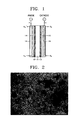
- FIG. 2 is a TEM photograph of a catalyst impregnated carbon in which Pt catalyst particles are impregnated into a general spherical carbon support. According to FIG. 2, ultrafine Pt catalyst particles with a size of 2nm to 5nm are impregnated onto a surface of a carbon particle with a particle diameter of 0.1 ⁇ m.
- appropriate catalytic activity can be expected only when an amount of catalytic metal per the unit area of square centimeter is 3mg or greater. However, since an amount of the used catalyst is still much, it is necessary to improve an effective specific surface area of a catalyst.
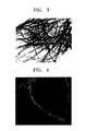
- FIG. 3 is a TEM photograph of a general single-walled carbon nanotube. This method using a carbon nanotube as a catalyst support was to utilize a good electric conductivity of a carbon nanotube and contributed to the improvement of an electrochemical reaction efficiency of a catalyst and an electrode power density. As seen from FIG. 3, the length of the carbon nanotube is very much higher than its diameter, so it is difficult to form a catalyst layer having a uniform distribution when forming a catalyst electrode.
- this carbon nanotube prepared by a conventional preparing method has its ends closed, so a catalyst may be impregnated onto only an outer surface of the carbon nanotube and is very difficult to be impregnated into an inner surface of the carbon nanotube. As a result, the power density is not satisfactorily improved.
- the carbon nanohorn refers to a cylindrical material having a structure similar to that of the closed end carbon nanotube, with a part of one closed end cut.
- a catalyst may be impregnated on the surface of the carbon nanohorn.
- the inner diameter of this conventional carbon nanohorn is quite small, e.g. about 1 nm, so that catalyst particles having a size of 1 nm or more can not be impregnated into the interior of this carbon nanohorn.
- a broad surface area characteristic which is a greatest advantage of the carbon nanohorn is not utilized.
- a fuel source since one end is closed, a fuel source may not smoothly flow when it is used as a catalyst support for a fuel cell, thereby deteriorating a fuel efficiency.
- the invention solves this problem by providing a carbon nanotube having the features of claim 1 and a fuel cell having the features of claim 8.
- Advantageous embodiments of the invention are mentioned in the subclaims, the wording of which is herewith incorporated into the specification by reference to avoid unnecessary text repetitions.
- the invention provides a carbon nanotube for a catalyst support, having a broad specific surface area and capable of impregnating catalyst particles into the inside thereof, thereby providing a maximum effective specific surface area of a catalyst.
- the invention also provides a catalyst impregnated carbon nanotube using the short carbon nanotube.
- the invention also provides a fuel cell using the catalyst impregnated carbon nanotube.
- a short carbon nanotube for a catalyst support having both ends opened, a length of about 300nm or less, and an aspect ratio of about one to about fifteen.
- a catalyst impregnated carbon nanotube in which metallic catalyst particles with an average particle size of about 1 nm to about 5nm, which are found to be of optimum size, are impregnated into an inner wall and an outer wall of a short carbon nanotube having both ends opened, a length of 300nm or less, and an aspect ratio of about one to about fifteen.
- a fuel cell prepared using the catalyst impregnated carbon nanotube.
- a short carbon nanotube for a catalyst support according to an embodiment of the present invention has both ends opened, a length of about 300nm or less, and an aspect ratio of about one to about fifteen.
- the catalyst when impregnating a catalyst, the catalyst can be impregnated to the inner side of the carbon nanotube and a reaction gas or liquid can be diffused through each opened end, thereby providing a maximum effective specific surface area of catalyst particles.
- a diameter of the carbon nanotube may be from about 10nm to about 50nm. It is difficult to prepare a carbon nanotube having a diameter less than 10nm and when a diameter of a carbon nanotube is greater than 50nm, the entire specific surface area of a catalyst is undesirably reduced.
- the length of the carbon nanotube may preferable be about 50nm or less, and the aspect ratio of the carbon nanotube may be between one and three. The shorter the carbon nanotube is, the more advantageous for impregnating a catalyst it is. When impregnating a catalyst into a carbon nanotube having a length and an aspect ratio within the above ranges, catalyst particles can have a maximum effective specific surface area.
- a structure of the carbon nanotube is not particularly restricted and may be multi-walled or single-walled.
- the carbon nanotube may have a metallic property because it can improve electrical conductivity when being used as an electrode in a fuel cell, and the like.
- the short carbon nanotube for a catalyst support may be prepared by shortening a length of a conventional carbon nanotube through mechanical and chemical methods.
- bonding forces between crystal carbons forming graphite are strong, processing is difficult and a preparing process may be complicated.
- a length of a carbon nanotube may be shortened by lowering a growth temperature during growth of the carbon nanotube of a chemical vapor deposition process using a catalyst.
- catalyst particles in the form of impurities may be applied to the stabilized carbide or graphite, or particles which are placed in the ends of a carbon nanotube, which is growing, to open the ends, thereby limiting growth of the carbon nanotube.
- the short carbon nanotube for a catalyst support may be prepared by injecting carbon source gas at a constant flow rate into a reactor while supplying metal carbonyl as a catalyst source in a gas or liquid state to the reactor to prepare a carbon nanotube, and then rapidly transferring the carbon nanotube from a high temperature region to a low temperature region immediately after the beginning of the growth of the carbon nanotube.
- the catalyst particles may be formed in the same manner as in a general method of preparing a carbon nanotube. That is, a catalytic metal layer of cobalt, nickel, iron, or an alloy thereof is formed on a substrate, and then the catalytic metal layer is etched by purging an etchant gas at a constant flow rate to form nano-sized catalytic metal particles.
- the short carbon nanotube for a catalyst support is prepared using the chemical vapor deposition.
- defects are formed at various positions on the carbon nanotube by rapidly halting the growth before the carbon nanotube significantly grows and then are cut, thereby opening both ends and controlling the length of the carbon nanotube to a maximum of 300nm.
- FIG. 4 is a TEM photograph of a carbon nanotube having defects, obtained during preparing a short carbon nanotube for a catalyst support according to an embodiment of the present invention.
- defects are at various positions on the carbon nanotube and are cut to shorten carbon nanotube.
- the defects are generated because crystallization dose not uniformly occur due to quick changes in the rate of growth of the carbon nanotube.
- the carbon nanotube may be cut during a growth phase to open an end or may be chemically treated with a strong acid once a growth phase is completed, to be first oxidized and cut at a defect portion so as to open an end.
- the catalytic metal particles used in the method of preparing the carbon nanotube of the present invention may be formed by supplying metal carbonyl in a liquid or gas state or by dispersing catalytic metal particle precursors on a substrate, and then reducing and etching with an etchant gas.
- the metal carbonyl is not particularly limited as long as it is known in the art, and iron carbonyl (Fe(CO) 6 ), nickel carbonyl (Ni(CO) 4 ), etc. may be used.
- the etchant gas may be hydrogen or ammonia but other gases known to those skilled in the art may also be used.
- the carbon source gas may be a common gas known to those skilled in the art, for example, methane, ethylene, or acetylene.
- a reactor is vertically installed and an upper portion is maintained at a temperature of 800°C to 1000°C and a lower portion is maintained at a temperature of 100°C or lower by being thermally isolated from the upper portion, thereby transferring resultants produced in the high temperature region to the low temperature region.
- a cooling device is placed at a side of a CVD apparatus and a reactor is transferred to the cooling device by a slide-type mechanical device so as to rapidly cool it.
- particles containing a catalyst are sprayed using nitrogen as a carrier gas to transfer a carbon nanotube to a low temperature region.
- a length of the short carbon nanotube for a catalyst support depends on how rapidly it is cooled, a flow rate of a carrier gas, etc. and a diameter thereof depends on a concentration and flow rate of the metal carbonyl supplied for forming a catalyst. Also, when a carbon nanotube is prepared after dispersing metallic catalyst particles on a substrate, the diameter of the carbon nanotube may be controlled by a degree of dispersion of the metallic catalyst particles.
- PECVD plasma enhanced chemical vapor deposition
- a carbon source gas is injected between two electrodes of a reactor containing a metallic catalyst and microwaves or radio waves is used to transform the carbon source gas into plasma by which a carbon nanotube is able to grow on the electrodes.
- “Plasma” means a collection of electrons and gas ions generated when free electrons generated by a glow discharge obtain sufficient energy to collide with gas molecules.
- a melting point of the glass substrate is about 600°C, it may be melted when using the conventional thermal chemical vapor deposition. Meanwhile, a carbon nanotube may be synthesized at a relatively low temperature when using the PECVD.
- a shorter carbon nanotube may be prepared through an additional process. For example, it may be accomplished through ultrasonic treatment in a liquid under a strong oxidization atmosphere or high energy mechanical processing such as milling.
- additional shortening process is performed by a chemical method, additional effects such as impurities being removed from the carbon nanotube and a suitable surface for a metallic catalyst to be impregnated being provided may be obtained.
- a catalyst impregnated carbon nanotube In a catalyst impregnated carbon nanotube according to another embodiment, metallic catalyst particles with an average particle size of 1 nm to 5nm are impregnated onto an inner wall and an outer wall of a short carbon nanotube having both ends opened, a length of 300nm or less, and an aspect ratio of 1 to 15. Since a broad surface area and high electrical conductivity of a carbon nanotube are utilized, an amount of an impregnated catalyst per the unit area is maximized, and a reaction gas or liquid may be diffused through both opened ends, an area of a catalyst particle to be directly contacted with the reaction gas or liquid, i.e. an effective specific surface area of the catalyst particle increases.
- FIG. 8 schematically illustrates a structure of a catalyst impregnated carbon nanotube prepared according to the invention.
- the catalyst impregnated carbon nanotube has similar effects to a conventional impregnated catalyst using carbon powder even at lower amounts and has superior effects to the conventional impregnated catalyst when using the same amount of a catalyst per the unit area.
- the electrically conductive kinetics of the carbon nanotube ensure the highest electrical conductivity, and thus, an activity of catalyst particles can be maximized in relation to a collection of electric current produced.
- a surface area of the carbon nanotube capable of impregnating a catalyst increases, and thus, a decrease in power density is prevented and energy efficiency is improved even though reducing an amount of a catalytic metal per unit area. Accordingly, cost competitiveness of a product can be ensured.
- the catalyst impregnated carbon nanotube can be used in a fuel cell and as an electrode material in a general secondary battery or super capacitor.
- the catalyst impregnated carbon nanotube may be prepared by preparing a short carbon nanotube for a catalyst support according to an embodiment of the present invention, and then impregnating catalyst particles, such as Pt, using a known method, such as gas phase reduction.
- a metal salt solution of a catalytic metal precursor, such as a metal salt, in a solvent is impregnated into the carbon nanotube support and dried, and then the metal salt is reduced with hydrogen gas, etc. to impregnate the metallic catalyst.
- the catalytic metal precursor is not particularly restricted as long as it is a chloride of a catalytic metal.
- examples of the catalytic metal precursor include H 2 PtCl 6 and PtCl 2 .
- a diameter of a carbon nanotube used in the catalyst impregnated carbon nanotube may be 10nm to 50nm. It is difficult to prepare a carbon nanotube below this range, and when above this range an entire specific surface area of a catalyst is undesirably reduced, thereby reducing catalytic efficiency.
- a length of the carbon nanotube may be a maximum of 50nm and an aspect ratio of the carbon nanotube may be 1 to 3. As a carbon nanotube is shorter, it is more advantageous for impregnating a catalyst into the inside thereof. When impregnating a catalyst into a carbon nanotube having a length and an aspect ratio within the above ranges, catalyst particles can have a maximum effective specific surface area.
- a structure of the carbon nanotube is not particularly restricted and may be multi-walled or single-walled. It may have a metallic property because it can improve electric conductivity when being used as an electrode in a fuel cell, and the like.
- Metallic catalyst particles used in the catalyst impregnated carbon nanotube are not particularly restricted, but may be Pt or a Pt alloy when used in PEMFC or DMFC.
- the Pt alloy may be an alloy of Pt and Ti, Cr, Mn, Fe, Co, Ni, Cu, Ga, Zr, Hf, Ru, Ir, Pd, Os, or a mixture thereof.
- DMFC methanol is oxidized to generate carbon monoxide as a side product, which causes poisoning of a Pt catalyst. To prevent this poisoning, the Pt alloy catalyst may be used.
- An entire specific surface area of the catalyst impregnated carbon nanotube may be 1000m 2 /g or greater.
- the specific surface area is less than 1000m 2 /g, it is difficult to obtain catalytic metal particles with a fine size and catalytic efficiency is reduced.
- the catalyst impregnated carbon nanotube may be used as an active component in an electrode of a fuel cell.
- the electrode for a fuel cell may be prepared in a conventional manner.
- the catalyst impregnated carbon nanotube can be dispersed in a solution of an ionomer, such as Nafion, in isopropyl alcohol to prepare a slurry, and then the slurry is coated on a waterproof carbon paper through spray coating and then dried to obtain an electrode.
- an ionomer such as Nafion
- a fuel cell may be PEMFC and DMFC, but is not limited to these.
- Fuel cells may be divided into alkaline, phosphoric acid, molten carbonate salt, solid oxide, and solid polymer electrolyte fuel cells according to a type of an electrolyte used therein.
- the catalyst impregnated carbon nanotube is suitable for alkaline, phosphoric acid, and solid polymer electrolyte fuel cells.
- DMFC has the same structure as the solid polymer electrolyte fuel cell
- the catalyst impregnated carbon nanotube may also be used in DMFC. Since a liquid fuel may be efficiently diffused through the inside of the carbon nanotube having both ends opened, the catalyst impregnated carbon nanotube is particularly suitable for DMFC.
- Example 1 Preparation of a carbon nanotube for a catalyst support
- Nitrogen gas was purged into a vertical reactor at a rate of 500 standard cubic centimeter per minute (sccm) under atmospheric pressure while raising a temperature of an upper portion of the vertical reactor to 500°C. Then, to form a catalyst, iron carbonyl was supplied to the reactor in a gas state at a rate of 50sccm and the temperature was held constant at 1000°C. Next, acetylene as a carbon source gas was supplied to the reactor at a rate of 10sccm under atmospheric pressure for 60 minutes to synthesize a carbon nanotube.
- sccm standard cubic centimeter per minute
- the carbon nanotube was transferred to a lower portion of the reactor, which was thermally isolated from the upper portion and maintained at a maximum of 100°C, to obtain a short carbon nanotube.
- the obtained carbon nanotube had a diameter of 50nm and a length of 50nm.
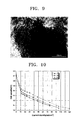
- An SEM photograph and a TEM photograph for the obtained carbon nanotube are illustrated in FIGS. 5 and 6, respectively.
- Example 2 Preparation of a short carbon nanotube for a catalyst support
- a short carbon nanotube was prepared in the same manner as Example 1 except that a flow rate of a carrier gas was 700sccm and a flow rate of iron carbonyl was 30sccm.
- the obtained carbon nanotube had a diameter of 30nm and a length of 40nm.
- a high resolution TEM photograph of the obtained carbon nanotube was illustrated in FIG. 7.
- Example 3 Preparation of a catalyst impregnated carbon nanotube
- Example 1 0.5g of the carbon nanotube prepared in Example 1 was placed in a vinyl bag and 0.9616g of H 2 PtCl 6 was weighted and dissolved in 0.8ml of acetone. The solution was placed in the vinyl bag containing the carbon support and mixed, and then 0.35ml of acetone was further added thereto and dissolved by thoroughly shaking. This process was repeated once again such that the total amount of acetone added was 1.5ml. The mixture was dried in air for 4 hours, then was transferred to a crucible and finally dried in a drier at 60°C overnight. Then, the crucible was placed in an electric furnace in which nitrogen was allowed to flow for 10 minutes.
- Example 4 Manufacturing of a fuel cell
- the catalyst impregnated carbon nanotube prepared in Example 3 was dispersed in a dispersion solution of Nafion 115 (available from Du-Pont) in isopropyl alcohol to prepare a slurry and was coated on a carbon electrode through a spray process so as to obtain a concentration of 1mg/cm 2 of the coated catalyst based on a Pt concentration. Then, the electrode was passed through a rolling machine to enhance adhesion between a catalyst layer and a carbon paper, thereby obtaining a cathode. Meanwhile, an anode prepared using a commercially available PtRu Black catalyst was used as an anode to prepare a unit cell.
- Performance of the unit cell prepared in Example 4 was measured at 30°C, 40°C, and 50°C while excessively supplying 2M methanol and air. The results are illustrated in FIG. 10. Although the fuel cell according to the invention used the catalyst per the unit area in an amount of 1mg/cm 2 or less, it had similar or superior performance to a conventional fuel cell using a catalyst per the unit area in an amount of 2mg/cm 2 to 4mg/cm 2 .
- the short carbon nanotube according to the invention has a broad surface area and better electric conductivity and has both ends opened, thereby impregnating a metallic catalyst onto the inside thereof.
- the catalyst impregnated carbon nanotube has a broad effective specific surface area, and thus, has improved efficiency of catalyst utilization, can reduce an amount of the catalyst used and can efficiently diffuse a fuel.
- improvements can be made in pricing, power density of an electrode and energy density of a fuel cell.
Landscapes
- Chemical & Material Sciences (AREA)
- Engineering & Computer Science (AREA)
- Materials Engineering (AREA)
- Nanotechnology (AREA)
- Chemical Kinetics & Catalysis (AREA)
- Organic Chemistry (AREA)
- Electrochemistry (AREA)
- General Chemical & Material Sciences (AREA)
- Physics & Mathematics (AREA)
- Condensed Matter Physics & Semiconductors (AREA)
- General Physics & Mathematics (AREA)
- Manufacturing & Machinery (AREA)
- Crystallography & Structural Chemistry (AREA)
- Inorganic Chemistry (AREA)
- Composite Materials (AREA)
- Carbon And Carbon Compounds (AREA)
- Catalysts (AREA)
- Inert Electrodes (AREA)
- Fuel Cell (AREA)
Applications Claiming Priority (2)
| Application Number | Priority Date | Filing Date | Title |
|---|---|---|---|
| KR2004000996 | 2004-01-07 | ||
| KR1020040000996A KR100561856B1 (ko) | 2004-01-07 | 2004-01-07 | 촉매 담체용 짧은 탄소나노튜브, 상기 탄소나노튜브를 이용한 탄소나노튜브 담지 촉매 및 이를 채용한 연료전지 |
Publications (2)
| Publication Number | Publication Date |
|---|---|
| EP1553052A2 true EP1553052A2 (fr) | 2005-07-13 |
| EP1553052A3 EP1553052A3 (fr) | 2006-05-31 |
Family
ID=34588127
Family Applications (1)
| Application Number | Title | Priority Date | Filing Date |
|---|---|---|---|
| EP04027819A Ceased EP1553052A3 (fr) | 2004-01-07 | 2004-11-24 | Nanotube de carbone et pile à combustible utilisant ce dernier |
Country Status (5)
| Country | Link |
|---|---|
| US (1) | US20100004121A1 (fr) |
| EP (1) | EP1553052A3 (fr) |
| JP (1) | JP3878642B2 (fr) |
| KR (1) | KR100561856B1 (fr) |
| CN (1) | CN100593016C (fr) |
Cited By (14)
| Publication number | Priority date | Publication date | Assignee | Title |
|---|---|---|---|---|
| EP1837939A2 (fr) | 2006-03-16 | 2007-09-26 | Samsung SDI Co., Ltd. | Catalyseur à cathode, assemblage membrane-électrode et système de pile à combustible le comprenant |
| WO2008054510A3 (fr) * | 2006-04-19 | 2008-08-07 | Ballard Power Systems | Pile à combustible avec des nanotubes de carbone |
| US7842432B2 (en) | 2004-12-09 | 2010-11-30 | Nanosys, Inc. | Nanowire structures comprising carbon |
| EP1710014A4 (fr) * | 2004-01-27 | 2011-01-05 | Showa Denko Kk | Support de catalyseur et pile a combustible l'utilisant |
| WO2011016855A1 (fr) * | 2009-08-04 | 2011-02-10 | Gentex Corporation | Matériaux cathodiques destinés à être utilisés dans des capteurs électrochimiques et dispositifs associés et procédés de fabrication de ces derniers |
| WO2010116238A3 (fr) * | 2009-04-09 | 2011-04-14 | Toyota Jidosha Kabushiki Kaisha | Procédé de production de nanotubes de carbone et appareil utilisable pour la production de nanotubes de carbone |
| US7939218B2 (en) | 2004-12-09 | 2011-05-10 | Nanosys, Inc. | Nanowire structures comprising carbon |
| WO2011128761A1 (fr) * | 2010-04-13 | 2011-10-20 | Toyota Jidosha Kabushiki Kaisha | Ensemble électrode à membrane, procédé de fabrication de ce dernier et cellule électrochimique |
| US8278011B2 (en) | 2004-12-09 | 2012-10-02 | Nanosys, Inc. | Nanostructured catalyst supports |
| US8357475B2 (en) | 2004-12-09 | 2013-01-22 | Nanosys, Inc. | Nanowire-based membrane electrode assemblies for fuel cells |
| TWI406809B (zh) * | 2006-09-01 | 2013-09-01 | Ihi Corp | 碳構造體之製造裝置及製造方法 |
| EP2406072A4 (fr) * | 2009-03-11 | 2016-03-16 | Univ Northeastern | Nanostructures à faible rapport d'allongement |
| CN107623131A (zh) * | 2016-07-14 | 2018-01-23 | 中国科学院大连化学物理研究所 | 基于铂或铂合金纳米管的膜电极的制备及其应用 |
| US10490817B2 (en) | 2009-05-19 | 2019-11-26 | Oned Material Llc | Nanostructured materials for battery applications |
Families Citing this family (31)
| Publication number | Priority date | Publication date | Assignee | Title |
|---|---|---|---|---|
| DE10317781A1 (de) | 2003-04-16 | 2004-11-04 | Cognis Deutschland Gmbh & Co. Kg | Poly-alpha-Olefin-haltige kosmetische Zusammensetzung |
| KR100647700B1 (ko) * | 2005-09-14 | 2006-11-23 | 삼성에스디아이 주식회사 | 담지 촉매 및 이를 이용한 연료전지 |
| JP4611958B2 (ja) * | 2005-10-18 | 2011-01-12 | 三星エスディアイ株式会社 | カーボンナノチューブの切断方法、フィールドエミッタおよびカーボンナノチューブの混成物質 |
| KR100773526B1 (ko) * | 2005-10-18 | 2007-11-07 | 삼성에스디아이 주식회사 | 카본나노튜브 절단방법 |
| KR100716036B1 (ko) | 2005-11-03 | 2007-05-08 | 부산대학교 산학협력단 | 카본 나노 파이버를 이용한 연료전지용 니켈 담지 촉매제조 장치 및 방법 |
| KR100716037B1 (ko) | 2005-11-03 | 2007-05-11 | 부산대학교 산학협력단 | 카본 나노 파이버를 이용한 연료전지용 니켈-백금 담지촉매 제조 장치 및 방법 |
| KR100716034B1 (ko) | 2005-11-03 | 2007-05-11 | 부산대학교 산학협력단 | 카본 나노 파이버를 이용한 연료전지용 철-백금 담지 촉매 제조 장치 및 방법 |
| RU2323157C2 (ru) * | 2005-11-07 | 2008-04-27 | Российская Федерация в лице Федерального агентства по атомной энергии | Способ очистки гелия от примеси изотопов водорода |
| KR100740351B1 (ko) * | 2005-12-23 | 2007-07-19 | 주식회사 두산 | 촉매담지체, 및 촉매담지체를 포함하는 멤브레인 전극어셈블리의 제조방법 및 이를 이용한 연료전지 |
| US7842639B2 (en) * | 2006-05-19 | 2010-11-30 | The United States Of America As Represented By The Administrator Of The National Aeronautics And Space Administration | Mechanical alloying of a hydrogenation catalyst used for the remediation of contaminated compounds |
| JP5205730B2 (ja) * | 2006-09-28 | 2013-06-05 | 大日本印刷株式会社 | 固体高分子型燃料電池用触媒転写フィルム |
| KR100801470B1 (ko) | 2007-02-15 | 2008-02-12 | 한국에너지기술연구원 | 탄소 종이 표면에 탄소나노튜브를 직접 성장시키고, 그탄소나노튜브 표면에 화학기상증착법을 사용하여 백금을담지시킨 백금 나노촉매의 제조방법과 그 백금 나노촉매 |
| US20090264277A1 (en) * | 2007-04-17 | 2009-10-22 | Dr. Rishi Raj | Picoscale catalysts for hydrogen catalysis |
| JP5269352B2 (ja) * | 2007-06-08 | 2013-08-21 | 学校法人早稲田大学 | 単層カーボンナノチューブ製造方法、半導体配線構造の製造方法、フィールドエミッションディスプレイ用電子部品の製造方法及び探針製造方法 |
| JP5093665B2 (ja) * | 2008-02-20 | 2012-12-12 | 独立行政法人産業技術総合研究所 | カーボンナノチューブの切断方法、カーボンナノチューブ片、およびカーボンナノチューブ分散液 |
| KR101071778B1 (ko) | 2008-10-29 | 2011-10-11 | 현대자동차주식회사 | 고분자 전해질 막에 나노 표면 구조를 형성하기 위한 연료전지용 전극막 접합체 제조 방법 |
| EP2196260A1 (fr) * | 2008-12-02 | 2010-06-16 | Research Institute of Petroleum Industry (RIPI) | Nanocatalyseur d'hydrodésulfuration, son utilisation et son procédé de fabrication |
| WO2010124196A2 (fr) * | 2009-04-23 | 2010-10-28 | 3M Innovative Properties Company | Régulation de propriétés de catalyseur avec mélange de substances inorganiques |
| WO2013009720A2 (fr) | 2011-07-08 | 2013-01-17 | Fastcap Systems Corporation | Dispositif de stockage d'énergie haute température |
| US9558894B2 (en) | 2011-07-08 | 2017-01-31 | Fastcap Systems Corporation | Advanced electrolyte systems and their use in energy storage devices |
| CN102916199B (zh) * | 2011-08-05 | 2014-12-10 | 清华大学 | 燃料电池膜电极的制备方法 |
| CN102916198B (zh) * | 2011-08-05 | 2015-03-11 | 清华大学 | 燃料电池膜电极 |
| CN102956898B (zh) * | 2011-08-30 | 2015-11-25 | 清华大学 | 燃料电池 |
| JP6042314B2 (ja) * | 2012-12-04 | 2016-12-14 | 本田技研工業株式会社 | カーボンナノチューブ成長用基板及びその製造方法 |
| US20140205921A1 (en) * | 2013-01-18 | 2014-07-24 | Samsung Sdi Co., Ltd. | Catalyst for Fuel Cell, Electrode for Fuel Cell, Membrane-Electrode Assembly for Fuel Cell and Fuel Cell System Using the Same |
| TWI610374B (zh) * | 2013-08-01 | 2018-01-01 | 格芯公司 | 用於將搬運器晶圓接合至元件晶圓以及能以中段波長紅外光雷射燒蝕釋出之接著劑 |
| CN106513662B (zh) * | 2016-10-31 | 2019-03-19 | 中国航空工业集团公司北京航空材料研究院 | 一种碳纳米管快速短化及在金属粉末中均匀分散的方法 |
| KR102115601B1 (ko) * | 2017-03-16 | 2020-05-26 | 주식회사 엘지화학 | 구조체 |
| KR102068409B1 (ko) * | 2018-05-28 | 2020-01-20 | 서울과학기술대학교 산학협력단 | 전기화학적 성능이 개선된 연료전지 촉매용 복합체의 제조방법 및 이를 이용한 복합체 |
| JP7192613B2 (ja) * | 2019-03-28 | 2022-12-20 | 日本製鉄株式会社 | 触媒担体用炭素材料、触媒担体用炭素材料の製造方法、燃料電池用触媒層、及び燃料電池 |
| CN115498226A (zh) * | 2022-09-15 | 2022-12-20 | 深圳深科鹏沃科技有限公司 | 一种燃料电池ccm膜电极的制备方法以及制备装置 |
Family Cites Families (6)
| Publication number | Priority date | Publication date | Assignee | Title |
|---|---|---|---|---|
| US6683783B1 (en) * | 1997-03-07 | 2004-01-27 | William Marsh Rice University | Carbon fibers formed from single-wall carbon nanotubes |
| CA2335449A1 (fr) * | 1998-06-19 | 1999-12-23 | The Research Foundation Of The State University Of New York | Nanotubes de carbone autonomes alignes et leur synthese |
| US6331262B1 (en) * | 1998-10-02 | 2001-12-18 | University Of Kentucky Research Foundation | Method of solubilizing shortened single-walled carbon nanotubes in organic solutions |
| US6828054B2 (en) * | 2000-02-11 | 2004-12-07 | The Texas A&M University System | Electronically conducting fuel cell component with directly bonded layers and method for making the same |
| US20030091891A1 (en) * | 2001-01-16 | 2003-05-15 | Tomoaki Yoshida | Catalyst composition for cell, gas diffusion layer, and fuel cell comprising the same |
| WO2004109837A2 (fr) * | 2002-10-31 | 2004-12-16 | Carbon Nanotechnologies, Inc. | Electrode de pile a combustible comprenant des nanotubes de carbone |
-
2004
- 2004-01-07 KR KR1020040000996A patent/KR100561856B1/ko not_active Expired - Fee Related
- 2004-11-24 EP EP04027819A patent/EP1553052A3/fr not_active Ceased
- 2004-12-16 CN CN200410081936A patent/CN100593016C/zh not_active Expired - Fee Related
-
2005
- 2005-01-06 US US11/029,496 patent/US20100004121A1/en not_active Abandoned
- 2005-01-07 JP JP2005002997A patent/JP3878642B2/ja not_active Expired - Fee Related
Non-Patent Citations (2)
| Title |
|---|
| DRESSELHAUS M S ET AL: "Nanotechnology in Carbon Materials", NANOSTRUCTURED MATERIALS, ELSEVIER, NEW YORK, NY, US, vol. 9, no. 1-8, 1 January 1997 (1997-01-01), pages 33 - 42, XP004205354, ISSN: 0965-9773, DOI: 10.1016/S0965-9773(97)00016-0 * |
| SUMIO IIJIMA: "Carbon nanotubes: past, present, and future", PHYSICA B. CONDENSED MATTER, AMSTERDAM, NL, vol. 323, no. 1-4, 1 October 2002 (2002-10-01), pages 1 - 5, XP002633822, ISSN: 0921-4526, [retrieved on 20020407], DOI: 10.1016/S0921-4526(02)00869-4 * |
Cited By (29)
| Publication number | Priority date | Publication date | Assignee | Title |
|---|---|---|---|---|
| EP1710014A4 (fr) * | 2004-01-27 | 2011-01-05 | Showa Denko Kk | Support de catalyseur et pile a combustible l'utilisant |
| USRE46921E1 (en) | 2004-12-09 | 2018-06-26 | Oned Material Llc | Nanostructured catalyst supports |
| US7842432B2 (en) | 2004-12-09 | 2010-11-30 | Nanosys, Inc. | Nanowire structures comprising carbon |
| USRE48084E1 (en) | 2004-12-09 | 2020-07-07 | Oned Material Llc | Nanostructured catalyst supports |
| US7939218B2 (en) | 2004-12-09 | 2011-05-10 | Nanosys, Inc. | Nanowire structures comprising carbon |
| USRE45703E1 (en) | 2004-12-09 | 2015-09-29 | Oned Material Llc | Nanostructured catalyst supports |
| US8278011B2 (en) | 2004-12-09 | 2012-10-02 | Nanosys, Inc. | Nanostructured catalyst supports |
| US8357475B2 (en) | 2004-12-09 | 2013-01-22 | Nanosys, Inc. | Nanowire-based membrane electrode assemblies for fuel cells |
| US8440369B2 (en) | 2004-12-09 | 2013-05-14 | Nanosys, Inc. | Nanowire-based membrane electrode assemblies for fuel cells |
| EP1837939A2 (fr) | 2006-03-16 | 2007-09-26 | Samsung SDI Co., Ltd. | Catalyseur à cathode, assemblage membrane-électrode et système de pile à combustible le comprenant |
| EP1837939A3 (fr) * | 2006-03-16 | 2008-10-01 | Samsung SDI Co., Ltd. | Catalyseur à cathode, assemblage membrane-électrode et système de pile à combustible le comprenant |
| US8445162B2 (en) | 2006-03-16 | 2013-05-21 | Samsung Sdi Co., Ltd. | Cathode catalyst for fuel cell and membrane-electrode assembly for fuel cell and fuel cell system including same |
| WO2008054510A3 (fr) * | 2006-04-19 | 2008-08-07 | Ballard Power Systems | Pile à combustible avec des nanotubes de carbone |
| TWI406809B (zh) * | 2006-09-01 | 2013-09-01 | Ihi Corp | 碳構造體之製造裝置及製造方法 |
| EP2406072A4 (fr) * | 2009-03-11 | 2016-03-16 | Univ Northeastern | Nanostructures à faible rapport d'allongement |
| WO2010116238A3 (fr) * | 2009-04-09 | 2011-04-14 | Toyota Jidosha Kabushiki Kaisha | Procédé de production de nanotubes de carbone et appareil utilisable pour la production de nanotubes de carbone |
| US8784562B2 (en) | 2009-04-09 | 2014-07-22 | Toyota Jidosha Kabushiki Kaisha | Carbon nanotube production process and carbon nanotube production apparatus |
| US12469849B2 (en) | 2009-05-19 | 2025-11-11 | Oned Material, Inc. | Nanostructured materials for battery applications |
| US12224441B2 (en) | 2009-05-19 | 2025-02-11 | Oned Material, Inc. | Nanostructured materials for battery |
| US10490817B2 (en) | 2009-05-19 | 2019-11-26 | Oned Material Llc | Nanostructured materials for battery applications |
| US11233240B2 (en) | 2009-05-19 | 2022-01-25 | Oned Material, Inc. | Nanostructured materials for battery applications |
| US11600821B2 (en) | 2009-05-19 | 2023-03-07 | Oned Material, Inc. | Nanostructured materials for battery applications |
| US8951396B2 (en) | 2009-08-04 | 2015-02-10 | Gentex Corporation | Cathodic materials for use in electrochemical sensors and associated devices and methods of manufacturing the same |
| WO2011016855A1 (fr) * | 2009-08-04 | 2011-02-10 | Gentex Corporation | Matériaux cathodiques destinés à être utilisés dans des capteurs électrochimiques et dispositifs associés et procédés de fabrication de ces derniers |
| US8888979B2 (en) | 2009-08-04 | 2014-11-18 | Gentex Corporation | Cathodic materials for use in electrochemical sensors and associated devices and methods of manufacturing the same |
| US8641878B2 (en) | 2009-08-04 | 2014-02-04 | Gentex Corporation | Cathodic materials for use in electrochemical sensors and associated devices and methods of manufacturing the same |
| WO2011128761A1 (fr) * | 2010-04-13 | 2011-10-20 | Toyota Jidosha Kabushiki Kaisha | Ensemble électrode à membrane, procédé de fabrication de ce dernier et cellule électrochimique |
| CN107623131B (zh) * | 2016-07-14 | 2020-11-13 | 中国科学院大连化学物理研究所 | 基于铂或铂合金纳米管的膜电极的制备及其应用 |
| CN107623131A (zh) * | 2016-07-14 | 2018-01-23 | 中国科学院大连化学物理研究所 | 基于铂或铂合金纳米管的膜电极的制备及其应用 |
Also Published As
| Publication number | Publication date |
|---|---|
| KR20050072634A (ko) | 2005-07-12 |
| JP3878642B2 (ja) | 2007-02-07 |
| US20100004121A1 (en) | 2010-01-07 |
| CN100593016C (zh) | 2010-03-03 |
| KR100561856B1 (ko) | 2006-03-16 |
| EP1553052A3 (fr) | 2006-05-31 |
| CN1636869A (zh) | 2005-07-13 |
| JP2005194184A (ja) | 2005-07-21 |
Similar Documents
| Publication | Publication Date | Title |
|---|---|---|
| EP1553052A2 (fr) | Nanotube de carbone et pile à combustible utilisant ce dernier | |
| EP1655266B1 (fr) | Procédé de preparation d'une nanosphere de carbone avec au moins une ouverture, catalyseur impregné comprenant cette nanosphere de carbone et pile à combustible utilisant ce catalyseur | |
| US8083905B2 (en) | Carbon nanotubes for fuel cells, method for manufacturing the same, and fuel cell using the same | |
| JP4907163B2 (ja) | 燃料電池用電極、これを備えた燃料電池、及び燃料電池用電極の製造方法 | |
| KR100696463B1 (ko) | 고농도 탄소 담지 촉매, 그 제조방법, 상기 촉매를 이용한촉매전극 및 이를 이용한 연료전지 | |
| US8007957B2 (en) | Electrode for fuel cell, fuel cell system comprising the same, and method for preparing the same | |
| KR100728611B1 (ko) | 연료전지용 전극 촉매 및 그의 제조 방법 | |
| Daş et al. | Comparison of two different catalyst preparation methods for graphene nanoplatelets supported platinum catalysts | |
| US20130149632A1 (en) | Electrode catalyst for a fuel cell, method of preparing the same, and membrane electrode assembly and fuel cell including the electrode catalyst | |
| JP2002298861A (ja) | 燃料電池、燃料電池用電極およびその製造方法 | |
| Lee et al. | Recent progress of low-loaded platinum on well-functionalized carbon electrocatalysts for oxygen reduction reaction | |
| KR20230063021A (ko) | 백금-알칼리토금속 합금을 포함하는 복합체, 이를 포함하는 연료전지 및 수전해 전지 그리고 이의 제조방법 | |
| Saha et al. | Enhancement of PEMFC performance by using carbon nanotubes supported Pt Co alloy catalysts | |
| Li et al. | Preparation of Pt/XC-72@ CN electrocatalysts by the in-situ carbonization of ionic liquid for methanol oxidation | |
| JP7387948B1 (ja) | 燃料電池電極触媒 | |
| KR100741139B1 (ko) | 1 이상의 개방부를 갖는 탄소 나노 구형 입자, 그제조방법, 상기 탄소 나노 구형 입자를 이용한 탄소 나노구형 입자 담지촉매 및 이를 채용한 연료전지 |
Legal Events
| Date | Code | Title | Description |
|---|---|---|---|
| PUAI | Public reference made under article 153(3) epc to a published international application that has entered the european phase |
Free format text: ORIGINAL CODE: 0009012 |
|
| AK | Designated contracting states |
Kind code of ref document: A2 Designated state(s): AT BE BG CH CY CZ DE DK EE ES FI FR GB GR HU IE IS IT LI LU MC NL PL PT RO SE SI SK TR |
|
| AX | Request for extension of the european patent |
Extension state: AL HR LT LV MK YU |
|
| PUAL | Search report despatched |
Free format text: ORIGINAL CODE: 0009013 |
|
| AK | Designated contracting states |
Kind code of ref document: A3 Designated state(s): AT BE BG CH CY CZ DE DK EE ES FI FR GB GR HU IE IS IT LI LU MC NL PL PT RO SE SI SK TR |
|
| AX | Request for extension of the european patent |
Extension state: AL HR LT LV MK YU |
|
| RIC1 | Information provided on ipc code assigned before grant |
Ipc: B01J 35/02 20060101ALI20060411BHEP Ipc: B01J 35/00 20060101ALI20060411BHEP Ipc: B01J 23/42 20060101ALI20060411BHEP Ipc: B01J 21/18 20060101ALI20060411BHEP Ipc: H01M 8/10 20060101ALI20060411BHEP Ipc: H01M 4/96 20060101ALI20060411BHEP Ipc: C01B 31/02 20060101AFI20050519BHEP |
|
| 17P | Request for examination filed |
Effective date: 20060720 |
|
| AKX | Designation fees paid |
Designated state(s): DE FR GB |
|
| 17Q | First examination report despatched |
Effective date: 20070619 |
|
| STAA | Information on the status of an ep patent application or granted ep patent |
Free format text: STATUS: THE APPLICATION HAS BEEN REFUSED |
|
| 18R | Application refused |
Effective date: 20141014 |