EP1553061B1 - Vorrichtung zur herstellung von tafelglas - Google Patents
Vorrichtung zur herstellung von tafelglas Download PDFInfo
- Publication number
- EP1553061B1 EP1553061B1 EP03762882A EP03762882A EP1553061B1 EP 1553061 B1 EP1553061 B1 EP 1553061B1 EP 03762882 A EP03762882 A EP 03762882A EP 03762882 A EP03762882 A EP 03762882A EP 1553061 B1 EP1553061 B1 EP 1553061B1
- Authority
- EP
- European Patent Office
- Prior art keywords
- glass
- glass ribbon
- vapor
- film forming
- forming agent
- Prior art date
- Legal status (The legal status is an assumption and is not a legal conclusion. Google has not performed a legal analysis and makes no representation as to the accuracy of the status listed.)
- Expired - Lifetime
Links
Images


Classifications
-
- C—CHEMISTRY; METALLURGY
- C03—GLASS; MINERAL OR SLAG WOOL
- C03B—MANUFACTURE, SHAPING, OR SUPPLEMENTARY PROCESSES
- C03B35/00—Transporting of glass products during their manufacture, e.g. hot glass lenses, prisms
- C03B35/14—Transporting hot glass sheets or ribbons, e.g. by heat-resistant conveyor belts or bands
- C03B35/22—Transporting hot glass sheets or ribbons, e.g. by heat-resistant conveyor belts or bands on a fluid support bed, e.g. on molten metal
- C03B35/24—Transporting hot glass sheets or ribbons, e.g. by heat-resistant conveyor belts or bands on a fluid support bed, e.g. on molten metal on a gas support bed
- C03B35/246—Transporting continuous glass ribbons
-
- C—CHEMISTRY; METALLURGY
- C03—GLASS; MINERAL OR SLAG WOOL
- C03B—MANUFACTURE, SHAPING, OR SUPPLEMENTARY PROCESSES
- C03B17/00—Forming molten glass by flowing-out, pushing-out, extruding or drawing downwardly or laterally from forming slits or by overflowing over lips
- C03B17/06—Forming glass sheets
- C03B17/061—Forming glass sheets by lateral drawing or extrusion
- C03B17/062—Forming glass sheets by lateral drawing or extrusion combined with flowing onto a solid or gaseous support from which the sheet is drawn
-
- C—CHEMISTRY; METALLURGY
- C03—GLASS; MINERAL OR SLAG WOOL
- C03B—MANUFACTURE, SHAPING, OR SUPPLEMENTARY PROCESSES
- C03B17/00—Forming molten glass by flowing-out, pushing-out, extruding or drawing downwardly or laterally from forming slits or by overflowing over lips
- C03B17/06—Forming glass sheets
- C03B17/064—Forming glass sheets by the overflow downdraw fusion process; Isopipes therefor
-
- C—CHEMISTRY; METALLURGY
- C03—GLASS; MINERAL OR SLAG WOOL
- C03B—MANUFACTURE, SHAPING, OR SUPPLEMENTARY PROCESSES
- C03B35/00—Transporting of glass products during their manufacture, e.g. hot glass lenses, prisms
- C03B35/14—Transporting hot glass sheets or ribbons, e.g. by heat-resistant conveyor belts or bands
- C03B35/16—Transporting hot glass sheets or ribbons, e.g. by heat-resistant conveyor belts or bands by roller conveyors
- C03B35/18—Construction of the conveyor rollers ; Materials, coatings or coverings thereof
- C03B35/188—Rollers specially adapted for supplying a gas, e.g. porous or foraminous rollers with internal air supply
Definitions
- the present invention relates to an apparatus for manufacturing sheet glass, in particular an apparatus for manufacturing glass into a thin sheet, the glass having a high devitrification temperature.
- the overflow fusion process is a process wherein a glass ribbon is formed by converging streams of molten glass just under a lower converged edge portion of a forming body having a wedge-shaped form converging downwardly in section while flowing down the streams of molten glass along both lateral sides of the forming body, and wherein the glass ribbon is formed into thin sheet glass by downwardly pulling the glass ribbon so as to remove distortion remaining in the glass ribbon while gradually cooling the glass ribbon.
- Such a forming process needs to complete forming of the glass ribbon just after the streams of glass has converged just under the lower edge portion of the forming body having a wedge-shaped form in section and to prevent the glass ribbon from being deformed after completion of forming of the glass ribbon. For this reason, it has been difficult to obtain sheet glass having high precision if the glass has too high or low a viscosity in the vicinity of the lower edge portion of the forming body having a wedge-shaped form in section. In the case of forming by the conventional overflow fusion process, thin sheet glass has been manufactured such that the glass has a viscosity in a range from 30,000 to 1,000,000 poises at the lower edge portion of the forming body.
- the viscosity at the devitrification temperature of glass capable of being formed i.e., the viscosity at a temperature that glass is devitrified
- the viscosity at a temperature that glass is devitrified has been restricted.
- glass, which starts being devitrified at a low viscosity (which has a high devitrification temperature), such as glass having a viscosity of less than 30,000 poises at the devitrification temperature has not been able to be formed without being inherently devitrified.
- the conventional overflow fusion process has needed to downwardly pull a glass ribbon in a vertical direction until the glass ribbon has been completely solidified and be cut, which has required a tall building and an operation space extending long in a vertical direction. Further, the conventional overflow fusion process has a drawback that the distortion remaining in glass is removed in an insufficient way since it is impossible to have a sufficient annealing time because of a limitation to the height of the building.
- US-patent 1,627,428 describes a method of forming sheet glass, consisting of causing molten glass to flow along a directing means and around opposite sides of a tip portion disposed at the discharge end of the means, the glass merging at the outer edge of the tip portion and flowing therefrom in single sheet form.
- EP-A-0 884 283 describes a process for forming a glass sheet, which is a process for continuously forming a glass sheet, and which comprises a step of introducing a vapor film-forming agent, which is not vapor at least around room temperature and which is vapor at a temperature above the glass transition point of the glass, into a support composed of a structure or a material capable of internally containing liquid, and a step of sliding the support and the glass of which temperature is above the glass transition point against each other via a thin layer of a vaporized vapor film-forming agent.
- the present invention has been proposed in consideration of such circumstances. It is an object of the present invention to provide an apparatus for manufacturing thin sheet glass, which is capable of drastically easing known limitations to the viscosity of glass that glass, which is likely to be devitrified, cannot be formed by the overflow fusion process, and which is capable of easily forming even special glass having a high devitrification temperature, such as glass to be used as a substrate for a flat panel display or information recording medium.
- the present invention provides an apparatus for manufacturing a thin sheet glass, comprising a forming body including a main body having a cross-sectional shape converging downwardly, the main body being configured to converging streams of molten glass into a single glass ribbon at a lower converged edge portion thereof, the streams of the molten glass flowing down along both surface of the main body; and edge members, the edge members being configured to restrict a width of the molten glass, wherein the apparatus is configured such that the glass ribbon formed by the forming body is downwardly pulled to form the thin sheet glass; characterized in that the apparatus further comprises a non-contact support member disposed in the vicinity of the lower converged edge portion of the main body, the non-contact support member being configured to form a thin gas layer on a supporting surface thereof, wherein the glass ribbon is supported over an entire width thereof in a non-contact way by the non-contact support member in a course wherein the glass ribbon is downwardly pulled, wherein the non-contact support member comprises a rotary roller
- the present invention it is possible to reduce a force applied to a low viscous portion of the glass ribbon in the vicinity of the lower edge portion of the forming body since the glass ribbon, which has been formed by the forming body according to the overflow fusion process, is pulled down via the non-contact support member, which supports the glass ribbon in a non-contact state through the thin gas layer.
- the glass ribbon can be prevented from being abruptly extended by the own weight or a pulling force.
- the rotary roller is configured to support the pulled glass ribbon so as to manufacture a sheet of glass from the molten glass which has a viscosity of less than 30,000 poises at the lower edge portion of the main body.
- the present invention can form even special glass having a high devitrification temperature (having a viscosity of less than 30,000 poises at the devitrification temperature), such as glass to be used as a substrate for a flat panel display or information recording medium, since it is possible to apply the overflow fusion process without limitations to the viscosity of the glass ribbon.
- the rotary roller As the non-contact support member, the entire width of the pulled-down glass ribbon is supported by an upper portion of the peripheral surface of the rotary roller, and then the glass ribbon slides down along the peripheral surface of the rotary roller and is pulled in a downward direction again or is pulled in a horizontal direction.
- the rotary roller may be configured to rotate in a direction opposite to the direction to pull the glass ribbon.
- the pulled-down glass ribbon is supported by the inclined plate, and then the glass ribbon slides down along the inclined plate and is pulled in a downward direction again or is pulled in a horizontal direction.
- the glass ribbon can smoothly move without staying on the non-contact support member.
- the apparatus may comprise a non-contact horizontally pulling device, the non-contact horizontally pulling device being configured to horizontally pull, in a non-contact state through a thin gas layer, the glass ribbon, which is pulled down via the non-contact support member.
- the horizontally pulled glass ribbon has one side brought into contact with air and the other side brought into contact with the thin gas layer formed by the non-contact support member. Even if the glass ribbon is horizontally pulled, the glass ribbon can be gradually cooled since the air and the thin gas layer both have a small thermal conduction. Accordingly, it is possible to reliably remove distortion remaining in the glass since it is possible to ensure a sufficient annealing time without need of a tall building and an operation space extending long in a vertical direction as in the prior art employing the overflow fusion process.
- the non-contact horizontally pulling device in a specific preferred mode of the present invention comprises a direction-changing roller and a conveying supporter.
- the direction-changing roller includes a roller base member, which is made of a base material configured to contain a liquid therein or has a structure configured to contain a liquid therein, wherein a vapor-film forming agent, which is not in a gas state at a temperature in the vicinity of room temperature but is in a gas state at a temperature of not lower than the glass transformation point, is introduced in a liquid state into the roller base member, wherein the vapor-film forming agent is evaporated by high heat from the glass ribbon, and wherein the pulled-down glass ribbon is turned in a horizontal direction by the direction-changing roller through a thin gas layer, which is formed from an evaporated portion of the vapor-film forming agent.
- the conveying supporter includes a supporter base member, which is made of a base material configured to contain a liquid therein or has a structure configured to contain a liquid therein, wherein a vapor-film forming agent, which is not in a gas state at a temperature in the vicinity of room temperature but is in a gas state at a temperature of not lower than the glass transformation point, is introduced in a liquid state into the support base member, wherein the vapor-film forming agent is evaporated by high heat from the glass ribbon, and wherein the glass ribbon, which has been turned by the direction-changing roller, is conveyed and supported by the conveying supporter through a thin gas layer, which is formed from the evaporated portion of the vapor-film forming agent.
- Fig. 1 is a schematic view of the entire structure of an apparatus for manufacturing thin sheet glass, according to the present invention
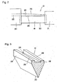
- Fig. 2 is a front view of a forming body
- Fig. 3 is a cross-sectional view of the forming body.
- the apparatus for manufacturing thin sheet glass 10, according to the present invention comprises the forming body 12; a non-contact support member 14 for supporting a glass ribbon GR over the entire width in a non-contact state, the glass ribbon being pulled down from the forming body 12; and a horizontally pulling device 16 for horizontally pulling the downwardly pulled glass ribbon GR in a non-contact state.
- the forming body 12 comprises a main body 18 having a wedge-shaped form converging downwardly in section, and lateral end members 20 and 21 disposed both side edges of the main body 18 to restrict the width of molten glass G.
- the lateral member 20 has a molten glass introduction hole 22 formed therein.
- the introduction hole 22 is connected to a melting furnace with refined molten glass G contained therein, and the introduction hole is used for supplying the molten glass G from the melting furnace to a channel 24 formed in the main body 18.
- the molten glass G supplied into the channel 24 flows along the channel 24 from a left side to a right side in Fig. 3 and overflows upper edges 26.
- the molten glass G that has overflowed flows downward along both surfaces 28 of the main body 18 as shown in Fig. 4 , and streams of the molten glass converge into a ribbon-shaped glass ribbon GR at a lower edge portion 30.
- a downwardly pulling force is applied to the glass ribbon GR by conveying driving rollers 60 stated later, whereby the glass ribbon GR is formed into desired thin sheet glass.
- the main body 18 is made of, e.g., a refractory material, such as an alumina material or a zirconia material, or a refractory material coated with refractory metal, such as platinum or a platinum alloy.
- the non-contact support member 14 may have any structure as long as the support member can support the glass ribbon GR over the entire width in a non-contact state through a thin gas layer 32 and as long as the glass ribbon GR can downwardly move in a smooth way without staying on the non-contact support member 14.
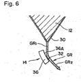
- a rotary roller 34 as shown in Fig. 4 or an inclined plate 36 as shown in Fig. 6 may be advantageously applicable.
- Fig. 4 shows a case wherein the non-contact support member 14 comprises the rotary roller 34.
- the rotary roller 34 is configured so that the roller includes a roller base member, which is made of a base material capable of containing a liquid therein or has a structure capable of containing a liquid therein, that a vapor-film forming agent, which is not in a gas state at a temperature in the vicinity of room temperature (about 20 to 30°C) but is in a gas state at a temperature of not lower than the glass transformation point, is introduced in a liquid state, that the vapor-film forming agent is evaporated by high heat from the glass ribbon GR, and that the glass ribbon GR is supported through a thin gas layer, which comprises a vapor film formed from an evaporated portion of the vapor-film forming agent.
- the rotary roller 34 has a peripheral portion 37 of a roller cylinder made of such a roller base member capable of containing the vapor-film forming agent therein, and both roller edge portions 38 and 38 are made from a base material with no vapor-film forming agent contained therein.
- the vapor-film forming agent introduced into the roller base member is evaporated from a roller surface 40 by high heat from the glass ribbon GR.
- the rotary roller 34 is rotated by an unshown electric motor.
- the glass ribbon GR can be supported in such a state that the thin glass layer 32 made of the vapor film is stably formed between the glass ribbon GR and the rotary roller 34.
- the rotary roller 34 may be rotated in either direction, it is more preferred that the rotary roller be rotated in the direction opposite to the direction to pull down the glass ribbon GR.
- the vapor-film forming agent may be spread into the entire roller base member by being supplied in a central hollow portion 46 defined between a rotary shaft 44 of the rotary roller 34 and the peripheral portion 37, or a wet roller (not shown) may be disposed so as to have contact with a side of the rotary roller 34 remote from the glass ribbon GR so that the vapor-film forming agent supplied to the wet roller is transferred onto the rotary roller. It is also acceptable to adopt a spray system wherein the vapor-film forming agent is sprayed on a surface of the rotary roller 34 by a nozzle. The point is that any supply method is acceptable as long as it is possible to supply the vapor-film forming agent so that the vapor-film forming agent can be sufficiently contained in the roller base member of the rotary roller 34.
- the roller base member is made of such a base material capable of containing a liquid therein or has such a structure capable of containing a liquid therein.
- a porous member or a fibrous material is advantageously employed.
- the porous member have through holes.
- the porous material has a surface formed with fine holes, which have a hole diameter of preferably 5 mm or below, more preferably 1 mm or below, or further preferably 100 ⁇ m or below. It is preferred that the roller base member be made of a material having a high affinity with the vapor-film forming agent.
- porous hydrophilic carbon is particularly appropriate.
- Other materials e.g., a polymer material derived from a natural product, such as cellulose, paper, wood or bamboo, a synthetic polymer material, such as a thermoplastic resin, a thermosetting resin or rubber, and a carbon material are advantageously applicable.
- a metal material such as iron, stainless steel or platinum, a metal oxide, such as an aluminum oxide, a zirconium oxide, silicon carbide or silicon nitride, metal carbide or metal nitride are also applicable.
- the vapor-film forming agent it is possible to employ various kinds of substances, which is an organic substance or inorganic substance that is liquid at room temperature and a gas at a temperature of not lower than the glass transformation point. From the viewpoint of supply operation to the forming body 12, it is preferred that the vapor-film forming agent have a melting point of not higher than 40°C and a boiling point of from 50 to 500°C, more preferably not higher than 300°C, at atmospheric pressure. It is additionally preferred that the vapor evaporated from the vapor-film forming agent do not react chemically with the glass or the rotary roller to such a degree to have an adverse effect on the glass or the rotary roller, and that the vapor have a low toxicity and be incombustible at a service temperature.
- Water may be employed as a typical example of the vapor-film forming agent.
- a liquid that can be instantly evaporated by high heat from the glass ribbon GR to form a stable vapor film. Since the thin glass layer 32 of the vapor film that is formed from a liquid instantly evaporated by high heat has a significantly lower thermal conductivity than a liquid or a solid material, the thin glass layer can effectively form a heat-insulated circumference for the glass ribbon GR.
- Fig. 6 shows a case, which is not within the scope of the present invention, wherein the non-contact support member 14 comprises the inclined plate 36.
- the inclined plate 36 is configured so that the inclined plate includes a plate base member, which is made of a base material capable of containing a liquid therein or has a structure capable of containing a liquid therein, that a vapor-film forming agent, which is not in a gas state at a temperature in the vicinity of room temperature but is in a gas state at a temperature of not lower than the glass transformation point, is introduced in a liquid state, that the vapor-film forming agent is evaporated by high heat from the glass ribbon GR, that the glass ribbon GR is supported through a thin gas layer 32, which comprise a vapor-film formed from an evaporated portion of the vapor-film forming agent, and that the inclined plate has a supporting surface 36A inclined so as not to be perpendicular to the direction to pull the glass ribbon GR.
- the plate base member forming the inclined plate 36, the basic material of the plate base member, the vapor-film forming agent, and the method for providing the inclined plate 36 with the vapor-film forming agent are similar to those in the rotary roller 34 stated earlier.
- the vapor-film forming agent introduced into the plate base member is evaporated from the inclined plate 36 by high heat from the glass ribbon GR, the glass ribbon GR can be supported in such a state that the thin glass layer 34 of the vapor film is stably formed between the glass ribbon GR and the inclined plate 36.
- the inclined plate 36 In connection with to what degree the inclined plate 36 should be inclined with respect to the horizontal direction, it is sufficient that the inclined plate is inclined at such an angle that the glass ribbon GR supported by the inclined plate 36 can smoothly move without staying on the inclined plate. In this case, it is preferred to make the inclination angle of the inclined plate 36 variable according to a viscosity and a thickness since whether or not the glass ribbon GR can smoothly move on the inclined plate or not is affected by the viscosity and the thickness of the glass ribbon GR. It is preferred from the viewpoint of easily supporting the glass ribbon GR that the supporting surface 36A of the inclined plate that supports the glass ribbon GR is curved in a concave shape.
- the non-contact horizontally pulling device 16 is a device wherein the glass ribbon GR, which is pulled down via the non-contact support member 14, is horizontally pulled in a non-contact state through a thin glass layer 32.
- the non-contact horizontally pulling device comprises a direction-changing roller 48 for directing the pulled-down glass ribbon GR to a horizontal direction in a non-contact state, and a conveying supporter 50 for conveying and supporting the horizontally-pulled glass ribbon GR in a non-contact state. Since the structure of the direction-changing roller 48 is similar to that of the rotary roller 34 stated earlier, explanation of the direction-changing roller will be omitted.
- the conveying supporter 50 of Fig. 1 is of fixed bed type.
- a plurality of rectangular supporting members 52 are disposed so as not to be movable at least in a direction parallel with the direction to convey the glass ribbon GR, and adjacent supporting members 52 have a groove 54 formed therebetween so as to escape vapor evaporated from the vapor-film forming agent.
- Each of the grooves 54 is important for releasing vapor of the thin glass layer 32, which comprises a vapor film formed between the supporting members 52 and the glass ribbon GR.
- the respective supporting members 52 are supported by a base 58 through posts 56.
- the supporter base member forming each of the supporting member 52, the basic material of the supporter base member, the vapor-film forming agent, and the method for providing the vapor-film forming agent to the supporting members are similar to those of the rotary roller 34 stated earlier.
- the pulling tension that pulls the glass ribbon GR above the supporting members 52 in the conveying direction is created by contact resistance between the plural conveying driving rollers 60 and the glass ribbon GR.
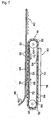
- the conveying supporter 50 of Fig. 7 is of conveyor type, wherein a plurality of supporting members 52 are fixedly disposed in a longitudinal direction at intervals on a surface of an endless belt 62 of a belt conveyor 61. Adjacent supporting members 52 have a groove 54 formed therebetween so as to extend in a direction perpendicular to the direction to convey the glass ribbon GR.
- the endless belt 62 extends between a pair of rollers comprising a driving roller 64 and a driven roller 66, and the endless belt moves in a clockwise direction 68 or in a counterclockwise direction 70 in Fig. 7 .
- the moving speed of the endless belt 62 is set so as to be different from the conveying speed of the glass ribbon GR above the supporting members 52.
- the belt conveyor 62 is provided with guide plates 72 for guiding the endless belt 62 on an upper moving path, and a portion of the endless belt 62, which is moving in the upper moving path, moves in a stable way, being guided by the guide plates 72.
- the supporter base member forming each of the supporting members 52, the basic material of the supporter base member and the vapor-film forming agent are similar to those of the rotary roller 34 stated earlier.
- the endless belt 62 has a supply vessel 74 for the vapor-film forming agent provided in a lower moving path. When supporting members 52 are moving through the lower moving path, the supporting members 52 are supplied with the vapor-film forming agent, passing through the supply vessel 74.
- the glass ribbon GR which has been formed at the lower edge portion 30 of the forming body 12 is pulled down via the non-contact support member 14, the glass ribbon is pulled in a non-contact state and in a horizontal direction by the non-contact horizontally pulling device 16 to be formed into thin sheet glass.
- the glass ribbon GR which has been formed by the forming body 12, is supported over the entire width in a non-contact state through the thin glass layer 32.
- the own weight of a portion GR 1 of the glass ribbon upstream from the non-contact support member 14 is supported by the non-contact support member 14, and the own weight of a portion GR 2 of the glass ribbon downstream from the non-contact support member and the pulling force are restricted from being applied to the upstream portion GR 1 of the glass ribbon.
- the forces that are applied to portions of the glass ribbon having a low viscosity in the vicinity of the lower edge portion of the forming body 12 are minimized.
- the glass ribbon GR is prevented from being abruptly extended by the own weight or the pulling force.
- the present invention can prevent the glass ribbon GR from being abruptly cooled since the glass ribbon GR is supported through the thin glass layer 32 having a small thermal conduction. Additionally, the glass ribbon GR cannot be damaged since the glass ribbon GR is supported over the entire width through the thin glass layer 32 to prevent the glass ribbon GR from being brought in direct contact with the non-contact support member 14.
- the apparatus is configured so that even when the glass ribbon GR is horizontally pulled, the glass ribbon GR, which is pulled down via the non-contact support member 14, is turned by the direction-changing roller 48 through the thin glass layer 32 having a small thermal conduction, and the glass ribbon GR thus turned is conveyed and supported by the conveying supporter 50 through the thin glass layer 32 having a small thermal conduction.
- the glass ribbon GR can be gradually cooled while the glass ribbon GR is horizontally pulled.
- the apparatus for forming thin sheet glass, of the present invention it is possible to drastically ease known limitations to the viscosity of glass that glass, which is likely to be devitrified, cannot be formed by the overflow fusion process, and to easily form even special glass having a high devitrification temperature, such as glass to be used as a substrate for a flat panel display or information recording medium. Additionally, in accordance with the present invention, it is possible to reliably remove distortion remaining in glass since it is possible to ensure a sufficient annealing time without need of a tall building and an operation space extending long in a vertical direction.
Landscapes
- Chemical & Material Sciences (AREA)
- Engineering & Computer Science (AREA)
- Materials Engineering (AREA)
- Organic Chemistry (AREA)
- Surface Treatment Of Glass (AREA)
- Re-Forming, After-Treatment, Cutting And Transporting Of Glass Products (AREA)
Claims (5)
- Vorrichtung zum Herstellen eines dünnen Tafelglases (10), umfassend einen formgebenden Körper (12), enthaltend einen Hauptkörper (18) mit einer Querschittsform, die nach unten konvergiert, wobei der Hauptkörper (18) gestaltet ist, um an einem unteren konvergierten Kantenbereich (30) davon Flüsse von geschmolzenem Glas in ein einzelnes Glasband zu konvergieren, wobei die Flüsse des geschmolzenen Glases entlang beider Oberflächen (28) des Hauptkörpers (18) hinunter fließen; und Kantenelemente, wobei die Kantenelemente gestaltet sind, um eine Breite des geschmolzenen Glases einzuschränken, wobei die Vorrichtung (10) so gestaltet ist, dass das durch den formgebenden Körper (12) gebildete Glasband nach unten gezogen wird, um das dünne Tafelglas zu bilden; dadurch gekennzeichnet, dass
die Vorrichtung (10) weiter ein berührungsfreies Trägerelement (14) umfasst, das in der Nähe des unteren konvergierten Kantenbereichs (30) des Hauptkörpers (18) angeordnet ist, wobei das berührungsfreie Trägerelement (14) gestaltet ist, um eine dünne Gasschicht (32) auf einer Trägeroberfläche davon zu bilden, wobei das Glasband über eine gesamte Breite davon in einer berührungsfreien Weise durch das berührungsfreie Trägerelement (14) in einem Verlauf, in welchem das Glasband nach unten gezogen wird, getragen wird, wobei das berührungsfreie Trägerelement (14) eine drehbare Rolle (34) umfasst, wobei die drehbare Rolle (34) ein Rollenbasiselement einschließt, welches aus einem Basismaterial hergestellt ist, das gestaltet ist, um darin eine Flüssigkeit zu enthalten oder eine Struktur aufweist, die gestaltet ist, um darin eine Flüssigkeit zu enthalten, wobei ein Dampfschichtbildungsmittel, welches nicht in einem Gaszustand bei einer Temperatur in der Nähe von Raumtemperatur ist, aber in einem Gaszustand bei einer Temperatur von nicht niedriger als der Glastransformationspunkt ist, in einem flüssigen Zustand in das Rollenbasiselement eingeführt ist, wobei das Dampfschichtbildungsmittel durch hohe Wärme von dem Glasband verdampft wird, und wobei das Glasband durch eine dünne Gasschicht (32) getragen wird, welche von einem verdampften Teil des Dampfschichtbildungsmittels gebildet wird. - Vorrichtung (10) nach Anspruch 1, wobei die drehbare Rolle (34) gestaltet ist, um das gezogene Glasband zu tragen, um so eine Glasplatte aus dem geschmolzenen Glas herzustellen, welches an dem unteren konvergierten Kantenbereich (30) des Hauptkörpers (18) eine Viskosität von weniger als 30.000 Poise aufweist.
- Vorrichtung (10) nach Anspruch 1 oder 2, wobei die drehbare Rolle (34) gestaltet ist, um in eine Richtung zu rotieren, die entgegen einer Richtung ist, um das Glasband nach unten zu ziehen.
- Vorrichtung (10) nach einem der Ansprüche 1 bis 3, weiter umfassend eine berührungsfreie horizontal ziehende Vorrichtung (16), wobei die berührungsfreie horizontal ziehende Vorrichtung (16) gestaltet ist, um das Glasband, welches über das berührungsfreie Trägerelement (14) nach unten gezogen wird, in einem berührungsfreien Zustand über eine dünne Gasschicht (32) horizontal zu ziehen.
- Vorrichtung (10) nach Anspruch 4, wobei die berührungsfreie horizontal ziehende Vorrichtung (16) eine richtungsändernde Rolle (48) und einen Förderträger (50) umfasst;
wobei die richtungsändernde Rolle (48) ein Rollenbasiselement einschließt, welches aus einem Basismaterial hergestellt ist, das gestaltet ist, um darin eine Flüssigkeit zu enthalten oder eine Struktur aufweist, die gestaltet ist, um darin eine Flüssigkeit zu enthalten, wobei ein Dampfschichtbildungsmittel, welches nicht in einem Gaszustand bei einer Temperatur in der Nähe von Raumtemperatur ist, aber in einem Gaszustand bei einer Temperatur von nicht niedriger als der Glastransformationsspunkt ist, in einem flüssigen Zustand in das Rollenbasiselement eingeführt ist, wobei das Dampfschichtbildungsmittel durch hohe Wärme von dem Glasband verdampft wird, und wobei das nach unten gezogene Glasband durch die richtungsändernde Rolle (48) durch eine dünne Gasschicht (32), welche von einem verdampften Teil des Dampfschichtbildungsmittels gebildet wird, in eine horizontale Richtung gedreht wird; und
der Förderträger (50) ein Trägerbasiselement einschließt, welches aus einem Basismaterial hergestellt ist, das gestaltet ist, um darin eine Flüssigkeit zu enthalten oder eine Struktur aufweist, die gestaltet ist, um darin eine Flüssigkeit zu enthalten, wobei ein Dampfschichtbildungsmittel, welches nicht in einem Gaszustand bei einer Temperatur in der Nähe von Raumtemperatur ist, aber in einem Gaszustand bei einer Temperatur von nicht niedriger als der Glastransformationsspunkt ist, in einem flüssigen Zustand in das Rollenbasiselement eingeführt ist, wobei das Dampfschichtbildungsmittel durch hohe Wärme von dem Glasband verdampft wird, und wobei das Glasband, welches durch die richtungsändernde Rolle (48) gedreht wurde, durch den Förderträger (50) durch eine dünne Gasschicht (32), welche von einem verdampften Teil des Dampfschichtbildungsmittels gebildet wird, befördert und getragen wird.
Applications Claiming Priority (3)
| Application Number | Priority Date | Filing Date | Title |
|---|---|---|---|
| JP2002198946A JP4178444B2 (ja) | 2002-07-08 | 2002-07-08 | 薄板ガラスの製造装置及び製造方法 |
| JP2002198946 | 2002-07-08 | ||
| PCT/JP2003/008531 WO2004005204A1 (ja) | 2002-07-08 | 2003-07-04 | 薄板ガラスの製造装置 |
Publications (3)
| Publication Number | Publication Date |
|---|---|
| EP1553061A1 EP1553061A1 (de) | 2005-07-13 |
| EP1553061A4 EP1553061A4 (de) | 2007-11-07 |
| EP1553061B1 true EP1553061B1 (de) | 2011-09-21 |
Family
ID=30112442
Family Applications (1)
| Application Number | Title | Priority Date | Filing Date |
|---|---|---|---|
| EP03762882A Expired - Lifetime EP1553061B1 (de) | 2002-07-08 | 2003-07-04 | Vorrichtung zur herstellung von tafelglas |
Country Status (5)
| Country | Link |
|---|---|
| EP (1) | EP1553061B1 (de) |
| JP (1) | JP4178444B2 (de) |
| CN (1) | CN1266060C (de) |
| AU (1) | AU2003244208A1 (de) |
| WO (1) | WO2004005204A1 (de) |
Families Citing this family (17)
| Publication number | Priority date | Publication date | Assignee | Title |
|---|---|---|---|---|
| US20060042314A1 (en) * | 2004-08-27 | 2006-03-02 | Abbott John S Iii | Noncontact glass sheet stabilization device used in fusion forming of a glass sheet |
| EP1746076A1 (de) | 2005-07-21 | 2007-01-24 | Corning Incorporated | Verfahren zur Herstellung einer Glasscheibe mit schneller Abkühlung |
| JP2011207720A (ja) * | 2010-03-30 | 2011-10-20 | Nippon Electric Glass Co Ltd | 薄板ガラスおよびその製造方法 |
| JP5743182B2 (ja) * | 2010-11-19 | 2015-07-01 | 日本電気硝子株式会社 | ガラスフィルムの製造方法 |
| US20130047671A1 (en) * | 2011-08-29 | 2013-02-28 | Jeffrey T. Kohli | Apparatus and method for forming glass sheets |
| WO2013078040A1 (en) * | 2011-11-23 | 2013-05-30 | Corning Incorporated | Vapor deposition systems and processes for the protection of glass sheets |
| EP2865656A4 (de) | 2012-06-14 | 2016-04-27 | Nippon Electric Glass Co | Verfahren zur herstellung einer glasplatte mit einem gekrümmten teil und glasplatte mit einem gekrümmten teil |
| TWI597245B (zh) * | 2012-09-25 | 2017-09-01 | 康寧公司 | 處理連續玻璃帶之方法 |
| JP6112301B2 (ja) * | 2013-08-28 | 2017-04-12 | 日本電気硝子株式会社 | ガラスフィルムリボン製造装置及びガラスフィルムリボン製造方法並びにガラスロール |
| US10246365B2 (en) * | 2013-10-09 | 2019-04-02 | Corning Incorporated | Apparatus and method for forming thin glass articles |
| DE102014003257B4 (de) | 2014-03-12 | 2017-08-31 | Calsitherm Verwaltungs Gmbh | Vorrichtung zur Herstellung von Flachglas und Bausatz |
| CN105330132B (zh) * | 2015-12-03 | 2017-08-29 | 蚌埠玻璃工业设计研究院 | 一种金属结构的超薄平板玻璃溢流成型器 |
| CN105330133B (zh) * | 2015-12-03 | 2017-08-08 | 蚌埠玻璃工业设计研究院 | 一种用于生产超薄平板玻璃的单侧溢流成型器 |
| JP6748920B2 (ja) * | 2017-03-13 | 2020-09-02 | 日本電気硝子株式会社 | ガラスフィルムの製造方法 |
| EP3704045A1 (de) * | 2017-10-31 | 2020-09-09 | Corning Incorporated | Systeme und verfahren zur verarbeitung von dünnen glasbändern |
| CN108493196A (zh) | 2018-03-30 | 2018-09-04 | 京东方科技集团股份有限公司 | 一种衬底基板及其制作方法、设备、显示基板及显示装置 |
| JP2023067752A (ja) * | 2021-10-29 | 2023-05-16 | 株式会社オハラ | 光学ガラスの製造方法 |
Family Cites Families (6)
| Publication number | Priority date | Publication date | Assignee | Title |
|---|---|---|---|---|
| US1627428A (en) * | 1927-05-03 | Method and apjpabatbs j | ||
| US3433613A (en) * | 1966-01-26 | 1969-03-18 | Corning Glass Works | Sheet glass forming apparatus with means to transform vertical flows into a horizontal flow |
| US3537834A (en) * | 1968-08-07 | 1970-11-03 | Corning Glass Works | Maintaining sheet glass width |
| WO1997031868A1 (fr) * | 1996-02-29 | 1997-09-04 | Asahi Glass Company Ltd. | Processus de formation de verre plat |
| JP2001247320A (ja) * | 1999-12-28 | 2001-09-11 | Asahi Glass Co Ltd | 幅広板硝子の改良連続製法 |
| JP2002167226A (ja) * | 2000-11-29 | 2002-06-11 | Asahi Glass Co Ltd | 薄板ガラスの製造装置 |
-
2002
- 2002-07-08 JP JP2002198946A patent/JP4178444B2/ja not_active Expired - Fee Related
-
2003
- 2003-07-04 EP EP03762882A patent/EP1553061B1/de not_active Expired - Lifetime
- 2003-07-04 WO PCT/JP2003/008531 patent/WO2004005204A1/ja not_active Ceased
- 2003-07-04 AU AU2003244208A patent/AU2003244208A1/en not_active Abandoned
- 2003-07-04 CN CN 03815862 patent/CN1266060C/zh not_active Expired - Fee Related
Also Published As
| Publication number | Publication date |
|---|---|
| JP2004035381A (ja) | 2004-02-05 |
| EP1553061A1 (de) | 2005-07-13 |
| CN1266060C (zh) | 2006-07-26 |
| EP1553061A4 (de) | 2007-11-07 |
| CN1665748A (zh) | 2005-09-07 |
| AU2003244208A1 (en) | 2004-01-23 |
| WO2004005204A1 (ja) | 2004-01-15 |
| JP4178444B2 (ja) | 2008-11-12 |
Similar Documents
| Publication | Publication Date | Title |
|---|---|---|
| US20090217704A1 (en) | Apparatus for manufacturing sheet glass | |
| EP1553061B1 (de) | Vorrichtung zur herstellung von tafelglas | |
| KR101329867B1 (ko) | 유리기재로 플랫시트를 제조하는 공정 및 장치 | |
| KR102450782B1 (ko) | 유리 기재 프로세싱 장치 및 방법 | |
| US7913517B2 (en) | Process and apparatus for producing flat glass | |
| JP5678882B2 (ja) | 板ガラスの製造装置、及び板ガラスの製造方法 | |
| JP4218263B2 (ja) | 板硝子の製造方法 | |
| EP3055258B1 (de) | Verfahren zur herstellung dünner glasartikel | |
| KR20030041800A (ko) | 유리 리본 지지 장치 | |
| KR102705502B1 (ko) | 유리 제조 장치 및 방법들 | |
| JP4506919B2 (ja) | 幅広板硝子の製法 | |
| JP4560909B2 (ja) | 幅広板硝子の連続製法 | |
| JP2002193630A (ja) | 幅広板硝子の製造法改良 | |
| JP2001180950A (ja) | 連続薄肉板硝子の改良製法 | |
| JP2002249329A (ja) | 型板硝子の製法 | |
| JP2002047018A (ja) | 幅広板硝子の新規製法及びその装置 | |
| JP2001247320A (ja) | 幅広板硝子の改良連続製法 | |
| JP2001192218A (ja) | 連続薄肉板硝子の簡易製法 | |
| JP2002037635A (ja) | 幅広板硝子の製法 | |
| JP2001192220A (ja) | 連続板硝子の安定製法 |
Legal Events
| Date | Code | Title | Description |
|---|---|---|---|
| PUAI | Public reference made under article 153(3) epc to a published international application that has entered the european phase |
Free format text: ORIGINAL CODE: 0009012 |
|
| 17P | Request for examination filed |
Effective date: 20050113 |
|
| AK | Designated contracting states |
Kind code of ref document: A1 Designated state(s): AT BE BG CH CY CZ DE DK EE ES FI FR GB GR HU IE IT LI LU MC NL PT RO SE SI SK TR |
|
| AX | Request for extension of the european patent |
Extension state: AL LT LV MK |
|
| DAX | Request for extension of the european patent (deleted) | ||
| RBV | Designated contracting states (corrected) |
Designated state(s): BE CZ DE FR GB |
|
| A4 | Supplementary search report drawn up and despatched |
Effective date: 20071005 |
|
| 17Q | First examination report despatched |
Effective date: 20080219 |
|
| GRAP | Despatch of communication of intention to grant a patent |
Free format text: ORIGINAL CODE: EPIDOSNIGR1 |
|
| GRAS | Grant fee paid |
Free format text: ORIGINAL CODE: EPIDOSNIGR3 |
|
| GRAA | (expected) grant |
Free format text: ORIGINAL CODE: 0009210 |
|
| AK | Designated contracting states |
Kind code of ref document: B1 Designated state(s): BE CZ DE FR GB |
|
| REG | Reference to a national code |
Ref country code: GB Ref legal event code: FG4D |
|
| RAP2 | Party data changed (patent owner data changed or rights of a patent transferred) |
Owner name: ASAHI GLASS COMPANY, LIMITED |
|
| REG | Reference to a national code |
Ref country code: DE Ref legal event code: R096 Ref document number: 60338463 Country of ref document: DE Effective date: 20111117 |
|
| PLBE | No opposition filed within time limit |
Free format text: ORIGINAL CODE: 0009261 |
|
| STAA | Information on the status of an ep patent application or granted ep patent |
Free format text: STATUS: NO OPPOSITION FILED WITHIN TIME LIMIT |
|
| 26N | No opposition filed |
Effective date: 20120622 |
|
| REG | Reference to a national code |
Ref country code: DE Ref legal event code: R097 Ref document number: 60338463 Country of ref document: DE Effective date: 20120622 |
|
| PGFP | Annual fee paid to national office [announced via postgrant information from national office to epo] |
Ref country code: GB Payment date: 20140721 Year of fee payment: 12 Ref country code: FR Payment date: 20140721 Year of fee payment: 12 |
|
| PGFP | Annual fee paid to national office [announced via postgrant information from national office to epo] |
Ref country code: BE Payment date: 20140722 Year of fee payment: 12 |
|
| GBPC | Gb: european patent ceased through non-payment of renewal fee |
Effective date: 20150704 |
|
| PG25 | Lapsed in a contracting state [announced via postgrant information from national office to epo] |
Ref country code: GB Free format text: LAPSE BECAUSE OF NON-PAYMENT OF DUE FEES Effective date: 20150704 |
|
| REG | Reference to a national code |
Ref country code: FR Ref legal event code: ST Effective date: 20160331 |
|
| PG25 | Lapsed in a contracting state [announced via postgrant information from national office to epo] |
Ref country code: FR Free format text: LAPSE BECAUSE OF NON-PAYMENT OF DUE FEES Effective date: 20150731 |
|
| PG25 | Lapsed in a contracting state [announced via postgrant information from national office to epo] |
Ref country code: BE Free format text: LAPSE BECAUSE OF NON-PAYMENT OF DUE FEES Effective date: 20150731 |
|
| REG | Reference to a national code |
Ref country code: DE Ref legal event code: R082 Ref document number: 60338463 Country of ref document: DE Representative=s name: MUELLER-BORE & PARTNER PATENTANWAELTE PARTG MB, DE Ref country code: DE Ref legal event code: R081 Ref document number: 60338463 Country of ref document: DE Owner name: AGC INC., JP Free format text: FORMER OWNER: ASAHI GLASS COMPANY, LTD., TOKIO, JP |
|
| PGFP | Annual fee paid to national office [announced via postgrant information from national office to epo] |
Ref country code: CZ Payment date: 20180702 Year of fee payment: 16 |
|
| PGFP | Annual fee paid to national office [announced via postgrant information from national office to epo] |
Ref country code: DE Payment date: 20190719 Year of fee payment: 17 |
|
| PG25 | Lapsed in a contracting state [announced via postgrant information from national office to epo] |
Ref country code: CZ Free format text: LAPSE BECAUSE OF NON-PAYMENT OF DUE FEES Effective date: 20190704 |
|
| REG | Reference to a national code |
Ref country code: DE Ref legal event code: R119 Ref document number: 60338463 Country of ref document: DE |
|
| PG25 | Lapsed in a contracting state [announced via postgrant information from national office to epo] |
Ref country code: DE Free format text: LAPSE BECAUSE OF NON-PAYMENT OF DUE FEES Effective date: 20210202 |