EP1553230B1 - Méthode pour remettre en état des murs de soutènement - Google Patents
Méthode pour remettre en état des murs de soutènement Download PDFInfo
- Publication number
- EP1553230B1 EP1553230B1 EP20050000226 EP05000226A EP1553230B1 EP 1553230 B1 EP1553230 B1 EP 1553230B1 EP 20050000226 EP20050000226 EP 20050000226 EP 05000226 A EP05000226 A EP 05000226A EP 1553230 B1 EP1553230 B1 EP 1553230B1
- Authority
- EP
- European Patent Office
- Prior art keywords
- shaft
- wall
- load
- soil
- formwork
- Prior art date
- Legal status (The legal status is an assumption and is not a legal conclusion. Google has not performed a legal analysis and makes no representation as to the accuracy of the status listed.)
- Expired - Lifetime
Links
- 238000000034 method Methods 0.000 title claims description 30
- 238000009826 distribution Methods 0.000 claims description 45
- 239000002689 soil Substances 0.000 claims description 31
- 239000000463 material Substances 0.000 claims description 26
- 238000009415 formwork Methods 0.000 claims description 25
- 238000002347 injection Methods 0.000 claims description 5
- 239000007924 injection Substances 0.000 claims description 5
- 239000007788 liquid Substances 0.000 claims description 4
- 238000011065 in-situ storage Methods 0.000 claims 1
- 238000009420 retrofitting Methods 0.000 claims 1
- 238000011010 flushing procedure Methods 0.000 description 5
- 238000005192 partition Methods 0.000 description 4
- 230000001788 irregular Effects 0.000 description 3
- 238000009412 basement excavation Methods 0.000 description 2
- 230000006835 compression Effects 0.000 description 2
- 238000007906 compression Methods 0.000 description 2
- 230000000694 effects Effects 0.000 description 2
- 239000004570 mortar (masonry) Substances 0.000 description 2
- 238000009416 shuttering Methods 0.000 description 2
- 230000003068 static effect Effects 0.000 description 2
- 239000013589 supplement Substances 0.000 description 2
- XLYOFNOQVPJJNP-UHFFFAOYSA-N water Substances O XLYOFNOQVPJJNP-UHFFFAOYSA-N 0.000 description 2
- 229910000831 Steel Inorganic materials 0.000 description 1
- 239000011230 binding agent Substances 0.000 description 1
- 230000015572 biosynthetic process Effects 0.000 description 1
- 239000004568 cement Substances 0.000 description 1
- 239000000945 filler Substances 0.000 description 1
- 239000012530 fluid Substances 0.000 description 1
- 238000004519 manufacturing process Methods 0.000 description 1
- 239000002184 metal Substances 0.000 description 1
- 238000004321 preservation Methods 0.000 description 1
- 238000003825 pressing Methods 0.000 description 1
- 230000003014 reinforcing effect Effects 0.000 description 1
- 239000010802 sludge Substances 0.000 description 1
- 239000007787 solid Substances 0.000 description 1
- 238000007711 solidification Methods 0.000 description 1
- 230000008023 solidification Effects 0.000 description 1
- 239000010959 steel Substances 0.000 description 1
- 238000012795 verification Methods 0.000 description 1
Images




Classifications
-
- E—FIXED CONSTRUCTIONS
- E02—HYDRAULIC ENGINEERING; FOUNDATIONS; SOIL SHIFTING
- E02D—FOUNDATIONS; EXCAVATIONS; EMBANKMENTS; UNDERGROUND OR UNDERWATER STRUCTURES
- E02D29/00—Independent underground or underwater structures; Retaining walls
- E02D29/02—Retaining or protecting walls
- E02D29/0258—Retaining or protecting walls characterised by constructional features
- E02D29/0275—Retaining or protecting walls characterised by constructional features cast in situ
-
- E—FIXED CONSTRUCTIONS
- E02—HYDRAULIC ENGINEERING; FOUNDATIONS; SOIL SHIFTING
- E02D—FOUNDATIONS; EXCAVATIONS; EMBANKMENTS; UNDERGROUND OR UNDERWATER STRUCTURES
- E02D37/00—Repair of damaged foundations or foundation structures
Definitions
- the invention relates to a method for intercepting retaining walls with pending soil behind by subsequent attachment of load distribution bodies, wherein on the wall rear side generated in lateral intervals cavities and are precipitated with the load distribution body forming material.
- EP 0 272 473 B1 are flushed through horizontal holes through the retaining wall at the back of the wall by high pressure water flushing cavities, which are filled with cementitious material and form load distribution body in the form of pillar reserves.
- high pressure water flushing cavities which are filled with cementitious material and form load distribution body in the form of pillar reserves.
- the object of the invention is therefore to provide a method of the type mentioned in such a way that under Utilization of often limited access options behind the back of the wall load distribution body can be made, which are also statically verifiable.
- the load distribution bodies formed on the rear side of the wall at a distance from one another in particular absorb the earth pressure of the soil lying behind, in particular by vaulting, thus relieving the retaining wall.
- On the back of the wall load distribution body are generated with predetermined dimensions and testable quality, wherein at the earth's surface only a very small, essentially predetermined by the floor plan dimensions of the load distribution body space is required, which is sufficient for the suction.
- load distribution bodies are preferably enabled by the earth pressure to be anchored in the ground by essentially horizontal ground anchors introduced from the front of the wall on the principle of self-supporting earth nailing. This can also load distribution body of small dimensions for Recording high forces are used in statically verifiable and verifiable form.
- the load distribution bodies are formed by setting material and the ground anchors are after the setting of the material introduced by preferably horizontal holes from the front wall of the front.
- the method is also suitable to form pillar reserves as a load distribution body, which are preferably non-positively connected to the retaining wall and enable them to absorb the earth pressure on the heavy weight principle in a statically verifiable manner.
- a region of each cavity created by aspiration above the load distribution body can be filled with earth material, preferably again with the previously extracted earth material.
- the shaft walls are secured by a shaft wall formwork. This allows the process to be used even on difficult, non-cohesive soils.
- the shaft walls can be secured by a shaft wall formwork entrained during sinking, in which case the shaft wall formwork is pulled out of the shaft during the concreting process and the material forming the load distribution body is introduced.
- the shaft wall formwork for example, consist of releasably connected formwork segments.
- the drawback associated with the method of extracting soil material is that the walls of the created cavity are irregular, and that at greater depths and / or loose soil there is a risk of loose soil falling into the cavity, becomes easy in difficult, non-cohesive soils overcome by the use of the continuously entrained shaft wall formwork, which are pulled out when filling the cavity again.
- the shaft wall formwork is formed by a series of injections, through which a support liquid is pressed into the soil. In this way, even in cohesion-less, non-cohesive soils a fuse of the shaft is achieved without the need for separate formwork elements should be used.
- a cavity 4 is produced directly on the rear side 1 of a retaining wall 2 to be rehabilitated in the soil 3 present behind it.
- a shaft 6 is sunk.
- a separator 10 is arranged, which separates the subsidized earth material from the suction air stream.
- the cavity 4 is filled with setting, preferably cementitious material after the suction lance 7 has been pulled out. Since the excavation cross-section is so small that sets a vaulting effect in the soil and a collapse is not to be feared, a formwork is not required for cohesive soils.
- ground anchor 17 After setting of the load distribution body 14 forming material ground anchor 17 are introduced through bores 16 from the front wall front, which anchor the load distribution body 14 in the ground 3.
- the load distribution body 14 largely absorb the earth pressure and carry it off into the upcoming soil 3, so that the retaining wall 2 to be rehabilitated is relieved.
- the individual, arranged in lateral intervals load distribution body 14 are designed with relatively small width and depth, for example in the dimensions of 30 x 30 cm. At the earth's surface 5, the space requirement for producing the cavities 4 is barely greater than this plan of the respective load distribution body 14.
- the in the Fig. 4 and 5 illustrated variant of the method differs from the previously described variant only in that when sinking the shaft in cohesionless, non-cohesive soil a shaft wall formwork 11 is carried.
- the walls of the shaft 6 produced in this way are secured by the shaft wall formwork 11 carried along during the lowering, which consists of a plurality of shuttering segments 12 which are detachably connected to one another.
- the formwork segments are connected by only schematically indicated connecting elements 13 tension and pressure resistant together and preferably form box elements.
- the formwork segments 12 in plan are rectangular box elements and made of sheet metal.
- the shuttering segments can also be in plan U-shaped box elements and be open to the rear wall 1 back.
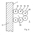
- a modified advantageous embodiment of the method is based on the Fig. 6 to 8 explained.
- Serving to secure the shaft to be excavated shaft wall formwork is hereby formed by a series of injections.
- several vertical injection bores 18 are performed around the manhole to be produced, through which a environmentally friendly supporting liquid, preferably a hydraulically setting material, for example cement material, is pressed.
- the supporting fluid penetrates into an in each case Fig. 6 indicated by dashed lines surrounding area 19 of each bore 18 and causes by setting a solidification of the loose soil in this area 19th
- the load distribution body 14 can be anchored in the ground 3 by one or more Erdvernagelept 17 introduced from the wall front side.
Landscapes
- Engineering & Computer Science (AREA)
- Structural Engineering (AREA)
- Life Sciences & Earth Sciences (AREA)
- General Life Sciences & Earth Sciences (AREA)
- Mining & Mineral Resources (AREA)
- Paleontology (AREA)
- Civil Engineering (AREA)
- General Engineering & Computer Science (AREA)
- Environmental & Geological Engineering (AREA)
- Bulkheads Adapted To Foundation Construction (AREA)
- Pit Excavations, Shoring, Fill Or Stabilisation Of Slopes (AREA)
Claims (9)
- Procédé pour étayer des murs de soutènement avec la masse de terre située derrière eux, par apport ultérieur de corps de répartition de charge, des cavités étant produites sur la face postérieure du mur à intervalles latéraux, et étant remplies avec le matériau formant les corps de répartition de charge, un puits (6) étant foré directement contre la face postérieure du mur (1) à partir de la surface de la terre (5) par aspiration de la terre en vue de former chaque cavité (4), seul un très faible espace prédéfini essentiellement par les dimensions en plan des corps de répartition de charge (14) étant nécessaire au niveau de la surface de la terre (5), lequel suffit pour l'opération d'aspiration, et le matériau formant le corps de répartition de charge (14) étant introduit dans le puits (6).
- Procédé selon la revendication 1, caractérisé en ce que les corps de répartition de charge (14) sont ancrés dans la terre (3) par des clous de sol (17) introduits depuis la face antérieure du mur.
- Procédé selon la revendication 2, caractérisé en ce que les corps de répartition de charge (14) sont formés par un matériau de prise et en ce que les clous de sol (17), après la prise du matériau formant les corps de répartition de charge (14), sont introduits à travers des alésages (16) depuis la face antérieure du mur.
- Procédé selon la revendication 2, caractérisé en ce que les corps de répartition de charge forment des renforts à pilier du mur de soutènement (2).
- Procédé selon la revendication 1, caractérisé en ce qu'une région (15) de chaque puits (6) subsistant au-dessus du corps de répartition de charge (14) est remplie de terre.
- Procédé selon la revendication 1, caractérisé en ce que les parois du puits sont fixées par un coffrage de puits.
- Procédé selon la revendication 1, caractérisé en ce que les parois du puits sont fixées par un coffrage de puits (11) entraîné lors du forage, et en ce que le coffrage de puits (11) est ressorti du puits (6) et le matériau formant le corps de répartition de charge (14) est introduit.
- Procédé selon la revendication 7, caractérisé en ce que le coffrage de puits (11) se compose de segments de coffrage (12) connectés de manière détachable les uns aux autres.
- Procédé selon la revendication 1, caractérisé en ce que le coffrage de puits est formé par une série d'injections par le biais desquelles un liquide de soutènement est introduit dans la terre.
Applications Claiming Priority (2)
| Application Number | Priority Date | Filing Date | Title |
|---|---|---|---|
| DE200410001559 DE102004001559B4 (de) | 2004-01-10 | 2004-01-10 | Verfahren zum Abfangen von Stützmauern |
| DE102004001559 | 2004-01-10 |
Publications (3)
| Publication Number | Publication Date |
|---|---|
| EP1553230A2 EP1553230A2 (fr) | 2005-07-13 |
| EP1553230A3 EP1553230A3 (fr) | 2006-02-08 |
| EP1553230B1 true EP1553230B1 (fr) | 2014-12-10 |
Family
ID=34585386
Family Applications (1)
| Application Number | Title | Priority Date | Filing Date |
|---|---|---|---|
| EP20050000226 Expired - Lifetime EP1553230B1 (fr) | 2004-01-10 | 2005-01-07 | Méthode pour remettre en état des murs de soutènement |
Country Status (2)
| Country | Link |
|---|---|
| EP (1) | EP1553230B1 (fr) |
| DE (1) | DE102004001559B4 (fr) |
Families Citing this family (1)
| Publication number | Priority date | Publication date | Assignee | Title |
|---|---|---|---|---|
| FR2969672B1 (fr) * | 2010-12-24 | 2014-02-07 | Soletanche Freyssinet | Procede de renforcement de la resistance au renversement des fondations d'un pylone |
Family Cites Families (7)
| Publication number | Priority date | Publication date | Assignee | Title |
|---|---|---|---|---|
| AT217676B (de) * | 1959-03-27 | 1961-10-10 | Hans Dipl Ing Martin | Verfahren zur Instandsetzung von bodenmechanisch beanspruchten Stützmauern, Gewölben u. dgl. |
| DE3408461A1 (de) * | 1984-03-08 | 1985-09-19 | Kurt G. Dipl.-Ing. 6100 Darmstadt Ross | Verfahren zur sanierung von stuetzmauern |
| US4776731A (en) * | 1986-11-26 | 1988-10-11 | Briggs Technology, Inc. | Method and apparatus for conveying solids using a high velocity vacuum |
| DE3644399A1 (de) * | 1986-12-24 | 1988-07-07 | Ross Kurt G | Verfahren zum abfangen von stuetzmauern |
| DE3716100A1 (de) * | 1987-05-14 | 1988-12-01 | Ross Kurt G | Verfahren zur sicherung von stuetzmauern |
| NL194007C (nl) * | 1992-07-27 | 2001-04-03 | Aannemingsbedrijf Cultuurweg B | Monoliet damwandstabilisering. |
| DE19520692A1 (de) * | 1995-06-07 | 1997-01-16 | Johann Katz Bautenschutz Mauer | Verfahren zum Herstellen einer Vertikalsperre gegen Wasser und Feuchtigkeit an der Außenfläche einer Gebäudegrundmauer sowie Vorrichtung zur Verwendung bei diesem Verfahren |
-
2004
- 2004-01-10 DE DE200410001559 patent/DE102004001559B4/de not_active Expired - Fee Related
-
2005
- 2005-01-07 EP EP20050000226 patent/EP1553230B1/fr not_active Expired - Lifetime
Also Published As
| Publication number | Publication date |
|---|---|
| EP1553230A2 (fr) | 2005-07-13 |
| DE102004001559A1 (de) | 2005-08-04 |
| DE102004001559B4 (de) | 2014-07-03 |
| EP1553230A3 (fr) | 2006-02-08 |
Similar Documents
| Publication | Publication Date | Title |
|---|---|---|
| DE69635549T2 (de) | Verfahren und vorrichtung zur errichtung von endlosen unterirdischen mauern | |
| DE3710822A1 (de) | Tiefbauwerk in grundwasserfuehrendem erdreich | |
| DE60002318T2 (de) | Verfahren zur bildung eines wasserdichtes und die kriechgrenze steigernden abschnittes | |
| DE102007003085B4 (de) | Verfahren zur Herstellung einer Dichtwand mit optimierten Betonfertigteilen | |
| DE3638664A1 (de) | Verfahren zum herstellen einer spundwand | |
| DE2917994C2 (de) | Verfahren zur Herstellung einer Baugrubenverbau- oder Stützwand aus Stahlbeton für Geländeeinschnitte | |
| EP0272473B1 (fr) | Procédé pour étayer les murs de soutènement | |
| CH585823A5 (en) | Concrete foundation for waterlogged ground - uses preliminary foundation walls and extending baseplate to form trough | |
| DE102004001559B4 (de) | Verfahren zum Abfangen von Stützmauern | |
| EP0333639B1 (fr) | Méthode pour construire une paroi de palplanches | |
| DE69316908T2 (de) | Polderprinzip und -verfahren unter verwendung von schutzwänden | |
| DE102018119213B4 (de) | Verfahren zur Herstellung eines Bauwerks | |
| DE102004040191B4 (de) | Verfahren zur Herstellung von Führungselementen | |
| AT523783B1 (de) | Verkleidung für eine Wandschale und Verfahren zur Herstellung | |
| DE3716750A1 (de) | Verfahren zum herstellen und niederbringen von gruendungsbauwerken | |
| DE4302986C2 (de) | Verfahren zur Herstellung eines Bauwerks in Deckelbauweise mit Stahlbetonfertigteil-Pfählen | |
| DE206878C (fr) | ||
| DE3335072C2 (de) | Ufereinfassungswand | |
| CH492835A (de) | Verfahren zur Herstellung von Senkbrunnen, Senkkästen oder von Schächten | |
| DE2942428A1 (de) | Verfahren zum ausbau von hafenanlagen o.dgl. | |
| DE3201601A1 (de) | Verfahren zum einbringen von spundwaenden o.dgl. in erdreich durch spuelung sowie bauelement zur durchfuehrung des verfahrens. | |
| EP1964978B1 (fr) | Procédé d'établissement d'une installation de quai et installation de quai | |
| DE711114C (de) | Verfahren zur Herstellung von im Gundwasser oder im offenen Wasser liegenden Bauwerken in aufgeloester Bauweise | |
| DE102010000589B4 (de) | Verfahren und Einrichtung zum Erstellen einer Spundwand | |
| DE102023119635A1 (de) | Stützwandkonstruktion, insbesondere zur Befestigung einer Böschung oder dergleichen, sowie Verfahren zu deren Herstellung |
Legal Events
| Date | Code | Title | Description |
|---|---|---|---|
| PUAI | Public reference made under article 153(3) epc to a published international application that has entered the european phase |
Free format text: ORIGINAL CODE: 0009012 |
|
| AK | Designated contracting states |
Kind code of ref document: A2 Designated state(s): AT BE BG CH CY CZ DE DK EE ES FI FR GB GR HU IE IS IT LI LT LU MC NL PL PT RO SE SI SK TR |
|
| AX | Request for extension of the european patent |
Extension state: AL BA HR LV MK YU |
|
| PUAL | Search report despatched |
Free format text: ORIGINAL CODE: 0009013 |
|
| AK | Designated contracting states |
Kind code of ref document: A3 Designated state(s): AT BE BG CH CY CZ DE DK EE ES FI FR GB GR HU IE IS IT LI LT LU MC NL PL PT RO SE SI SK TR |
|
| AX | Request for extension of the european patent |
Extension state: AL BA HR LV MK YU |
|
| RIC1 | Information provided on ipc code assigned before grant |
Ipc: E02D 29/02 20060101ALI20051221BHEP Ipc: E02D 37/00 20060101AFI20050314BHEP |
|
| 17P | Request for examination filed |
Effective date: 20060419 |
|
| AKX | Designation fees paid |
Designated state(s): AT BE BG CH CY CZ DE DK EE ES FI FR GB GR HU IE IS IT LI LT LU MC NL PL PT RO SE SI SK TR |
|
| RAP1 | Party data changed (applicant data changed or rights of an application transferred) |
Owner name: BAU-SANIERUNGSTECHNIK GMBH |
|
| RIN1 | Information on inventor provided before grant (corrected) |
Inventor name: ROSS, KURT G. |
|
| 17Q | First examination report despatched |
Effective date: 20110202 |
|
| GRAP | Despatch of communication of intention to grant a patent |
Free format text: ORIGINAL CODE: EPIDOSNIGR1 |
|
| GRAS | Grant fee paid |
Free format text: ORIGINAL CODE: EPIDOSNIGR3 |
|
| INTG | Intention to grant announced |
Effective date: 20140909 |
|
| GRAA | (expected) grant |
Free format text: ORIGINAL CODE: 0009210 |
|
| AK | Designated contracting states |
Kind code of ref document: B1 Designated state(s): AT BE BG CH CY CZ DE DK EE ES FI FR GB GR HU IE IS IT LI LT LU MC NL PL PT RO SE SI SK TR |
|
| REG | Reference to a national code |
Ref country code: GB Ref legal event code: FG4D Free format text: NOT ENGLISH |
|
| REG | Reference to a national code |
Ref country code: CH Ref legal event code: EP |
|
| REG | Reference to a national code |
Ref country code: IE Ref legal event code: FG4D Free format text: LANGUAGE OF EP DOCUMENT: GERMAN |
|
| REG | Reference to a national code |
Ref country code: AT Ref legal event code: REF Ref document number: 700739 Country of ref document: AT Kind code of ref document: T Effective date: 20150115 |
|
| REG | Reference to a national code |
Ref country code: DE Ref legal event code: R096 Ref document number: 502005014615 Country of ref document: DE Effective date: 20150122 |
|
| REG | Reference to a national code |
Ref country code: FR Ref legal event code: PLFP Year of fee payment: 11 |
|
| REG | Reference to a national code |
Ref country code: NL Ref legal event code: VDEP Effective date: 20141210 |
|
| REG | Reference to a national code |
Ref country code: NL Ref legal event code: VDEP Effective date: 20141210 |
|
| PG25 | Lapsed in a contracting state [announced via postgrant information from national office to epo] |
Ref country code: LT Free format text: LAPSE BECAUSE OF FAILURE TO SUBMIT A TRANSLATION OF THE DESCRIPTION OR TO PAY THE FEE WITHIN THE PRESCRIBED TIME-LIMIT Effective date: 20141210 Ref country code: FI Free format text: LAPSE BECAUSE OF FAILURE TO SUBMIT A TRANSLATION OF THE DESCRIPTION OR TO PAY THE FEE WITHIN THE PRESCRIBED TIME-LIMIT Effective date: 20141210 Ref country code: ES Free format text: LAPSE BECAUSE OF FAILURE TO SUBMIT A TRANSLATION OF THE DESCRIPTION OR TO PAY THE FEE WITHIN THE PRESCRIBED TIME-LIMIT Effective date: 20141210 |
|
| PGFP | Annual fee paid to national office [announced via postgrant information from national office to epo] |
Ref country code: MC Payment date: 20150128 Year of fee payment: 11 |
|
| REG | Reference to a national code |
Ref country code: LT Ref legal event code: MG4D |
|
| PG25 | Lapsed in a contracting state [announced via postgrant information from national office to epo] |
Ref country code: GR Free format text: LAPSE BECAUSE OF FAILURE TO SUBMIT A TRANSLATION OF THE DESCRIPTION OR TO PAY THE FEE WITHIN THE PRESCRIBED TIME-LIMIT Effective date: 20150311 Ref country code: SE Free format text: LAPSE BECAUSE OF FAILURE TO SUBMIT A TRANSLATION OF THE DESCRIPTION OR TO PAY THE FEE WITHIN THE PRESCRIBED TIME-LIMIT Effective date: 20141210 |
|
| PGFP | Annual fee paid to national office [announced via postgrant information from national office to epo] |
Ref country code: FR Payment date: 20150129 Year of fee payment: 11 |
|
| PG25 | Lapsed in a contracting state [announced via postgrant information from national office to epo] |
Ref country code: NL Free format text: LAPSE BECAUSE OF FAILURE TO SUBMIT A TRANSLATION OF THE DESCRIPTION OR TO PAY THE FEE WITHIN THE PRESCRIBED TIME-LIMIT Effective date: 20141210 |
|
| PGFP | Annual fee paid to national office [announced via postgrant information from national office to epo] |
Ref country code: BE Payment date: 20150119 Year of fee payment: 11 |
|
| PG25 | Lapsed in a contracting state [announced via postgrant information from national office to epo] |
Ref country code: EE Free format text: LAPSE BECAUSE OF FAILURE TO SUBMIT A TRANSLATION OF THE DESCRIPTION OR TO PAY THE FEE WITHIN THE PRESCRIBED TIME-LIMIT Effective date: 20141210 Ref country code: SK Free format text: LAPSE BECAUSE OF FAILURE TO SUBMIT A TRANSLATION OF THE DESCRIPTION OR TO PAY THE FEE WITHIN THE PRESCRIBED TIME-LIMIT Effective date: 20141210 Ref country code: CZ Free format text: LAPSE BECAUSE OF FAILURE TO SUBMIT A TRANSLATION OF THE DESCRIPTION OR TO PAY THE FEE WITHIN THE PRESCRIBED TIME-LIMIT Effective date: 20141210 Ref country code: RO Free format text: LAPSE BECAUSE OF FAILURE TO SUBMIT A TRANSLATION OF THE DESCRIPTION OR TO PAY THE FEE WITHIN THE PRESCRIBED TIME-LIMIT Effective date: 20141210 Ref country code: PT Free format text: LAPSE BECAUSE OF FAILURE TO SUBMIT A TRANSLATION OF THE DESCRIPTION OR TO PAY THE FEE WITHIN THE PRESCRIBED TIME-LIMIT Effective date: 20150410 |
|
| PG25 | Lapsed in a contracting state [announced via postgrant information from national office to epo] |
Ref country code: PL Free format text: LAPSE BECAUSE OF FAILURE TO SUBMIT A TRANSLATION OF THE DESCRIPTION OR TO PAY THE FEE WITHIN THE PRESCRIBED TIME-LIMIT Effective date: 20141210 Ref country code: IS Free format text: LAPSE BECAUSE OF FAILURE TO SUBMIT A TRANSLATION OF THE DESCRIPTION OR TO PAY THE FEE WITHIN THE PRESCRIBED TIME-LIMIT Effective date: 20150410 |
|
| REG | Reference to a national code |
Ref country code: DE Ref legal event code: R097 Ref document number: 502005014615 Country of ref document: DE |
|
| PLBE | No opposition filed within time limit |
Free format text: ORIGINAL CODE: 0009261 |
|
| STAA | Information on the status of an ep patent application or granted ep patent |
Free format text: STATUS: NO OPPOSITION FILED WITHIN TIME LIMIT |
|
| PG25 | Lapsed in a contracting state [announced via postgrant information from national office to epo] |
Ref country code: DK Free format text: LAPSE BECAUSE OF FAILURE TO SUBMIT A TRANSLATION OF THE DESCRIPTION OR TO PAY THE FEE WITHIN THE PRESCRIBED TIME-LIMIT Effective date: 20141210 |
|
| REG | Reference to a national code |
Ref country code: IE Ref legal event code: MM4A |
|
| 26N | No opposition filed |
Effective date: 20150911 |
|
| GBPC | Gb: european patent ceased through non-payment of renewal fee |
Effective date: 20150310 |
|
| PG25 | Lapsed in a contracting state [announced via postgrant information from national office to epo] |
Ref country code: IT Free format text: LAPSE BECAUSE OF FAILURE TO SUBMIT A TRANSLATION OF THE DESCRIPTION OR TO PAY THE FEE WITHIN THE PRESCRIBED TIME-LIMIT Effective date: 20141210 |
|
| PG25 | Lapsed in a contracting state [announced via postgrant information from national office to epo] |
Ref country code: GB Free format text: LAPSE BECAUSE OF NON-PAYMENT OF DUE FEES Effective date: 20150310 Ref country code: IE Free format text: LAPSE BECAUSE OF NON-PAYMENT OF DUE FEES Effective date: 20150107 |
|
| PG25 | Lapsed in a contracting state [announced via postgrant information from national office to epo] |
Ref country code: SI Free format text: LAPSE BECAUSE OF FAILURE TO SUBMIT A TRANSLATION OF THE DESCRIPTION OR TO PAY THE FEE WITHIN THE PRESCRIBED TIME-LIMIT Effective date: 20141210 |
|
| PG25 | Lapsed in a contracting state [announced via postgrant information from national office to epo] |
Ref country code: BE Free format text: LAPSE BECAUSE OF NON-PAYMENT OF DUE FEES Effective date: 20160131 |
|
| PG25 | Lapsed in a contracting state [announced via postgrant information from national office to epo] |
Ref country code: MC Free format text: LAPSE BECAUSE OF NON-PAYMENT OF DUE FEES Effective date: 20160201 |
|
| REG | Reference to a national code |
Ref country code: FR Ref legal event code: ST Effective date: 20160930 |
|
| PG25 | Lapsed in a contracting state [announced via postgrant information from national office to epo] |
Ref country code: FR Free format text: LAPSE BECAUSE OF NON-PAYMENT OF DUE FEES Effective date: 20160201 |
|
| PG25 | Lapsed in a contracting state [announced via postgrant information from national office to epo] |
Ref country code: BG Free format text: LAPSE BECAUSE OF FAILURE TO SUBMIT A TRANSLATION OF THE DESCRIPTION OR TO PAY THE FEE WITHIN THE PRESCRIBED TIME-LIMIT Effective date: 20141210 Ref country code: HU Free format text: LAPSE BECAUSE OF FAILURE TO SUBMIT A TRANSLATION OF THE DESCRIPTION OR TO PAY THE FEE WITHIN THE PRESCRIBED TIME-LIMIT; INVALID AB INITIO Effective date: 20050107 |
|
| PG25 | Lapsed in a contracting state [announced via postgrant information from national office to epo] |
Ref country code: CY Free format text: LAPSE BECAUSE OF FAILURE TO SUBMIT A TRANSLATION OF THE DESCRIPTION OR TO PAY THE FEE WITHIN THE PRESCRIBED TIME-LIMIT Effective date: 20141210 |
|
| PG25 | Lapsed in a contracting state [announced via postgrant information from national office to epo] |
Ref country code: TR Free format text: LAPSE BECAUSE OF FAILURE TO SUBMIT A TRANSLATION OF THE DESCRIPTION OR TO PAY THE FEE WITHIN THE PRESCRIBED TIME-LIMIT Effective date: 20141210 |
|
| PGFP | Annual fee paid to national office [announced via postgrant information from national office to epo] |
Ref country code: AT Payment date: 20210129 Year of fee payment: 17 |
|
| REG | Reference to a national code |
Ref country code: AT Ref legal event code: MM01 Ref document number: 700739 Country of ref document: AT Kind code of ref document: T Effective date: 20220107 |
|
| PG25 | Lapsed in a contracting state [announced via postgrant information from national office to epo] |
Ref country code: AT Free format text: LAPSE BECAUSE OF NON-PAYMENT OF DUE FEES Effective date: 20220107 |
|
| PGFP | Annual fee paid to national office [announced via postgrant information from national office to epo] |
Ref country code: LU Payment date: 20240122 Year of fee payment: 20 |
|
| PGFP | Annual fee paid to national office [announced via postgrant information from national office to epo] |
Ref country code: DE Payment date: 20231106 Year of fee payment: 20 Ref country code: CH Payment date: 20240202 Year of fee payment: 20 |
|
| REG | Reference to a national code |
Ref country code: DE Ref legal event code: R071 Ref document number: 502005014615 Country of ref document: DE |
|
| REG | Reference to a national code |
Ref country code: CH Ref legal event code: PL |