EP1553310B1 - Vorrichtung zur lösbaren Verriegelung eines Endstückes auf einer Struktur mit verstellbarer Position - Google Patents
Vorrichtung zur lösbaren Verriegelung eines Endstückes auf einer Struktur mit verstellbarer Position Download PDFInfo
- Publication number
- EP1553310B1 EP1553310B1 EP05356009A EP05356009A EP1553310B1 EP 1553310 B1 EP1553310 B1 EP 1553310B1 EP 05356009 A EP05356009 A EP 05356009A EP 05356009 A EP05356009 A EP 05356009A EP 1553310 B1 EP1553310 B1 EP 1553310B1
- Authority
- EP
- European Patent Office
- Prior art keywords
- ring
- sleeve
- rod
- locking
- pin
- Prior art date
- Legal status (The legal status is an assumption and is not a legal conclusion. Google has not performed a legal analysis and makes no representation as to the accuracy of the status listed.)
- Expired - Lifetime
Links
- 230000002441 reversible effect Effects 0.000 title claims description 6
- 230000000295 complement effect Effects 0.000 claims description 9
- 230000006835 compression Effects 0.000 claims description 2
- 238000007906 compression Methods 0.000 claims description 2
- 238000010079 rubber tapping Methods 0.000 description 7
- 208000031968 Cadaver Diseases 0.000 description 3
- 230000000694 effects Effects 0.000 description 2
- 241000731961 Juncaceae Species 0.000 description 1
- 240000008042 Zea mays Species 0.000 description 1
- 230000000903 blocking effect Effects 0.000 description 1
- 230000001186 cumulative effect Effects 0.000 description 1
- 230000001419 dependent effect Effects 0.000 description 1
- 230000006355 external stress Effects 0.000 description 1
- 230000001939 inductive effect Effects 0.000 description 1
- 230000014759 maintenance of location Effects 0.000 description 1
- 239000000463 material Substances 0.000 description 1
- 230000037452 priming Effects 0.000 description 1
- 230000003252 repetitive effect Effects 0.000 description 1
- 230000000717 retained effect Effects 0.000 description 1
- 239000007787 solid Substances 0.000 description 1
- 230000035882 stress Effects 0.000 description 1
Images

Classifications
-
- F—MECHANICAL ENGINEERING; LIGHTING; HEATING; WEAPONS; BLASTING
- F16—ENGINEERING ELEMENTS AND UNITS; GENERAL MEASURES FOR PRODUCING AND MAINTAINING EFFECTIVE FUNCTIONING OF MACHINES OR INSTALLATIONS; THERMAL INSULATION IN GENERAL
- F16B—DEVICES FOR FASTENING OR SECURING CONSTRUCTIONAL ELEMENTS OR MACHINE PARTS TOGETHER, e.g. NAILS, BOLTS, CIRCLIPS, CLAMPS, CLIPS OR WEDGES; JOINTS OR JOINTING
- F16B7/00—Connections of rods or tubes, e.g. of non-circular section, mutually, including resilient connections
- F16B7/18—Connections of rods or tubes, e.g. of non-circular section, mutually, including resilient connections using screw-thread elements
- F16B7/182—Connections of rods or tubes, e.g. of non-circular section, mutually, including resilient connections using screw-thread elements for coaxial connections of two rods or tubes
-
- F—MECHANICAL ENGINEERING; LIGHTING; HEATING; WEAPONS; BLASTING
- F16—ENGINEERING ELEMENTS AND UNITS; GENERAL MEASURES FOR PRODUCING AND MAINTAINING EFFECTIVE FUNCTIONING OF MACHINES OR INSTALLATIONS; THERMAL INSULATION IN GENERAL
- F16B—DEVICES FOR FASTENING OR SECURING CONSTRUCTIONAL ELEMENTS OR MACHINE PARTS TOGETHER, e.g. NAILS, BOLTS, CIRCLIPS, CLAMPS, CLIPS OR WEDGES; JOINTS OR JOINTING
- F16B7/00—Connections of rods or tubes, e.g. of non-circular section, mutually, including resilient connections
- F16B7/04—Clamping or clipping connections
- F16B7/0406—Clamping or clipping connections for rods or tubes being coaxial
- F16B7/0413—Clamping or clipping connections for rods or tubes being coaxial for tubes using the innerside thereof
- F16B7/042—Clamping or clipping connections for rods or tubes being coaxial for tubes using the innerside thereof with a locking element, e.g. pin, ball or pushbutton, engaging in a hole in the wall of at least one tube
-
- F—MECHANICAL ENGINEERING; LIGHTING; HEATING; WEAPONS; BLASTING
- F16—ENGINEERING ELEMENTS AND UNITS; GENERAL MEASURES FOR PRODUCING AND MAINTAINING EFFECTIVE FUNCTIONING OF MACHINES OR INSTALLATIONS; THERMAL INSULATION IN GENERAL
- F16C—SHAFTS; FLEXIBLE SHAFTS; ELEMENTS OR CRANKSHAFT MECHANISMS; ROTARY BODIES OTHER THAN GEARING ELEMENTS; BEARINGS
- F16C7/00—Connecting-rods or like links pivoted at both ends; Construction of connecting-rod heads
- F16C7/06—Adjustable connecting-rods
Definitions
- the present invention relates to a reversible locking device of a tip on a structure and more specifically to a locking / unlocking device which, in an unlocked configuration, allows adjustment in "tension", that is to say adjustment of the spacing between the tip and the structure and which, in a locked configuration, securely freezes the adjustment made.
- the invention is generally applicable to areas in which tips or the like are to be assembled in an adjusted manner on a structure or more generally a chassis subsequently subjected to vibrations. This is for example the case of the aeronautical field in which components such as luggage boxes are to report to the fuselage of an aircraft.
- the endpiece is integral with an externally threaded rod, which is screwed inside a bore tapped in a complementary manner, delimited in the structure or, most often, in a rigid body integrally attached to the structure.
- the device In its locked configuration, the device is then intended to prohibit, or in any case to prevent as much as possible, the rotation of the nozzle relative to the structure to avoid changing the previously adjusted adjustment.
- a first solution is to conform the bottom of the receiving bore of the threaded rod into a truncated cone so that the free end of the rod is wedged inside. truncated cone as it progresses through screwing inside the bore.
- This solution has many disadvantages.
- First, the mechanical strength of the locking of the tip on the structure is low.
- the possible adjustment amplitude is limited by the slope of the wedge cone.
- a second solution consists in using a locking device comprising, on the one hand, a hexagon nut attached around the rigid body integral with the structure and, on the other hand, an articulated arm on the endpiece around a transverse axis. to the longitudinal direction of the threaded rod to be introduced into the bore of the rigid body.
- This arm is provided at its free end with a generally flexible sleeve shaped hex, complementary to the nut attached to the rigid body.
- This sleeve is open on a part of its periphery so as to be deformed radially to, when the articulated arm is tilted towards the rigid body, come to cap the nut, thus blocking in rotation the tip relative to the rigid body.
- this device has the advantage of being reversible, it does not guarantee a very effective locking since, due to the flexibility of the locking sleeve, the application of a high torque on the endpiece easily causes the deformation of the sleeve and, thereby, allows the rotation of the tip relative to the structure on at least one sixth of a turn. In addition, the locking sleeve of this device is difficult to handle.
- a locking assembly of two tubes to one another one of the tubes delimiting a threaded bore receiving the the threaded end of the other tube.
- This locking assembly comprises, around the ends of the tubes screwed into each other, a ring and a sleeve capable of being screwed to each other until this ring and this sleeve enclose flanges contiguous respectively integral with the two tubes.
- the locking of the two tubes is possible only if the screwing of these tubes to one another is sufficient for the flanges of the tubes are firmly contiguous against each other. If a free space remains between these flanges, the locking obtained by screwing one to the other of the ring and the sleeve does not prevent, thereafter, to modify, by screwing, the relative positions of the two tubes.
- the locking assembly proposed in GB-A-M26012 does not fall within the scope of the invention which allows a free adjustment "in tension" between the structure and the tip to lock.
- the object of the present invention is to provide a new reversible locking device, which ensures effective locking of the tip relative to the structure, even when this tip is stressed under a strong torque, while being easy and quick to maneuver .
- the subject of the invention is a device for reversibly locking a bit to a structure, comprising a rigid body integral with the structure and delimiting a tapped bore for receiving a rod secured to the endpiece and provided with an external thread complementary to the threaded bore, the end piece being locked by the device in a position, relative to the structure, which, before locking, is freely adjusted by screwing the rod into the bore of the body, characterized in that it comprises, on the one hand, a ring mounted around the rod both free in axial translation along the rod and connected in rotation with this rod and, on the other hand, a locking sleeve reversible ring bearing against the body, movably attached around the body.
- the sleeve is moved to block, including axially, the ring initially free to move in translation by relative to the rod, which causes the locking of the device.
- the rigidity of the components of the device ensures good mechanical strength in locked configuration.
- the device can be operated with one hand by successively operating the ring and the sleeve.
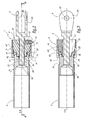
- the locking / unlocking device 1 shown in FIGS. 1 to 4 is adapted to mechanically lock an endpiece 2 on a tubular structure 3 of longitudinal axis X-X.
- the structure 3 is part of the chassis of a set of on-board luggage boxes on board an aircraft and the tip 2 is intended to be connected to the fuselage of the aircraft.
- the tip 2 comprises a front portion 21 in the form of a solid cylindrical rod, with a longitudinal axis coinciding with the axis X-X in the figures.
- the front portion of this rod 21 is provided with an outer thread 22.
- a rectilinear groove 23 is hollowed over the entire length of the rod.
- the rod 21 is secured to a stirrup 24 whose branches extend generally in directions parallel to the axis XX and are pierced right through by orifices 25 aligned in a direction substantially perpendicular to the XX axis.
- These orifices 25 are intended to receive an unrepresented rod for securing the nozzle 2 to a structural component not shown, for example a part of the fuselage of the aircraft, which, during its use, is subjected to mechanical stresses and / or vibrations inducing on the tip 2 a torque around the axis XX.
- the tip 2 is equipped with a rigid body 31 generally tubular and axis XX.
- This body is secured in a fixed manner to the structure 3 being for example force-fitted in the rear end of the structure.
- the body 31 is directly integral with the structure.
- the body 31 is traversed from side to side along the axis XX by an inner bore 32 threaded complementary to the outer thread 22 of the rod 21.
- the rod of the end piece 2 is able to be screwed in the bore 32 so as to adjust the axial spacing between the rigid body 31 and the stirrup 24, that is to say to adjust "in tension" the structure and the tip.
- the body 31 has a tubular zone 33 of inner diameter greater than the diameter of the bore, thus forming an internal radial shoulder 34.
- the rear end of this zone 33 is externally constituted by a flange 35 which extends radially protruding from the remainder of the outer surface of the body 31 by forming an outer radial shoulder 36.
- the inner surface 37 of the flange 35 is of frustoconical shape converging towards the axis XX, forwards .
- the device 1 also comprises a rigid ring 4 generally tubular, for example metallic.
- This ring can be threaded around the rod 21.
- a driving groove 41 extending over the entire length of the ring and substantially complementary to the groove 23 dug at the
- a generally cylindrical radial housing 46 within which are disposed a pin 51 and a compression spring 52 interposed radially between the base of the pin and the bottom of the housing.
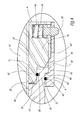
- the ring 4 is axially split along its entire length, as shown in FIG. 3, which corresponds to the plane of section passing through the corresponding slot 47.
- the device 1 furthermore comprises a generally tubular, for example metallic, rigid sleeve 6 that is movably mounted around the body 31 in a manner substantially coaxial with the bore 32.
- the sleeve 6 has an inside diameter substantially equal to outer diameter of the end flange 35 and is internally provided with a tapping 61 substantially complementary to the thread 45 of the ring 4.
- the sleeve 6 is provided with an end stub 62 extending radially inward and of inner diameter substantially equal to the outer diameter of the tubular body 31.
- the device 1 finally comprises two flexible annular rods 71 and 72 respectively housed in a groove 38 excavated in the rear portion 33 of the body 31, from its inner face, and in a groove 63 formed in the end heel 62 of the sleeve 6, from its inner face.
- the operation of the device 1 is as follows:
- the device 1 is in an unlocked configuration as shown in FIG. 1.
- the sleeve 6 is located in front of the rear end flange 35 of the body 31 and the ring 4 is freely movable. in axial translation between the rear end of the groove 23 and the body 31, the rod 21 being engaged inside the bore 32.
- the pin 51 extends, under the action of the spring 52, partially projecting from the outer surface of the rear portion 44 of the ring 4. Means not shown are provided to prevent the pin 51 from being completely disengaged from the housing 46.
- the tip 2 is then freely screwed and / or unscrewed into the body 31 so as to adjust the axial spacing between these elements.
- the user slides axially, in particular with one hand, the ring 4 forward until its frustoconical surface 43 comes into substantially contact with the frustoconical inner surface 37 of the flange. rear end 35 of the body 31.
- the ring 71 snaps inside an annular groove dug on the outer surface of the front portion 42 of the Ring. The ring is then axially retained relative to the body 31, the user having to overcome the resistance of the ring 71 if he wishes to disengage the ring backwards.
- the rigid sleeve 6 is used. Specifically, the sleeve passes from its position of Figure 1 to its position of Figures 2 to 4 being slid axially rearwardly until its inner thread 61 comes into axial abutment against the outer thread 45 of the ring.
- the ring 71 holds the ring axially and prevents it from being pushed backwards.
- the ring 4 is immobilized by the sleeve 6 relative to the tubular body 31 so that, when the end piece 2 is subsequently subjected to vibrations or external stresses, any rotational movement of the endpiece around of the XX axis is prevented.
- the direction of the thread 45 may be provided to cause an even greater tightening of the ring 4 by the sleeve 6 when the tip 2 is stressed by that of the two possible couples, which is of intensity and / or largest frequency. In this way, when this important or repetitive torque is applied to the tip 2, the device 1 causes somehow a more intense locking.
- the shoulder 34 however forms an abutment surface corresponding to the maximum permissible axial depression of the ring 4 in the body 31 to prevent damage to the device at its frustoconical surfaces 37 and 43.
- the extent of the material surfaces engaged at the thread 45 and the tapping 61 can be dimensioned in a high manner, by imposing a helix angle to this relatively small thread-tapping assembly, for example less than 30 °. . In this way, when the thread 45 is fully engaged with the tapping 61, the ring 4 and the sleeve 6 are in some way buttressed.
- the number of turns engaged with the thread 45 and the tapping 61 affects the resistance of the locking of the ring 4 by the sleeve 6.
- the device 1 When the device 1 is in its locking configuration and the user wishes to unlock it, it pushes the pin 51 radially inwardly, if necessary with the aid of a suitable tool, which constitutes an unlocking operation of which the user is necessarily conscious. It then unscrews partially forward the sleeve 6 having previously overcome the resistance of the rod 72. While the thread 45 is still partially engaged with the thread 61, it pushes axially rearwardly the sleeve 6, then causing axially the ring 4. The length adjustment of the nozzle 2 with respect to the structure 3 can then be modified or the sleeve 6 continues to be unscrewed until it disengages completely from the ring 4.
- the hole 64 is substantially complementary to the outer contour of the pin 51, the cooperation of this pin and this hole when the device 1 reaches its locking configuration, renders the presence of the flexible rod 72 unnecessary, the user having to overcome the resistance of the spring 62 to start unscrewing the sleeve 6.
Landscapes
- Engineering & Computer Science (AREA)
- General Engineering & Computer Science (AREA)
- Mechanical Engineering (AREA)
- Mutual Connection Of Rods And Tubes (AREA)
- Portable Nailing Machines And Staplers (AREA)
- Lock And Its Accessories (AREA)
- Electrophonic Musical Instruments (AREA)
- Quick-Acting Or Multi-Walled Pipe Joints (AREA)
- Fixing For Electrophotography (AREA)
- Spinning Or Twisting Of Yarns (AREA)
- Snaps, Bayonet Connections, Set Pins, And Snap Rings (AREA)
- Dowels (AREA)
Claims (10)
- Vorrichtung zur reversiblen Verriegelung eines Ansatzes (2) auf einer Struktur (3), die einen fest mit der Struktur verbundenen starren Körper (31) umfasst, der eine Gewindebohrung (32) zur Aufnahme eines fest mit dem Ansatz (2) verbundenen Stiftes (21) begrenzt, der mit einem Außengewinde (22), komplementär zur Gewindebohrung, versehen ist, wobei der Ansatz durch die Vorrichtung in Bezug auf die Struktur in einer Position verriegelt ist, die vor der Verriegelung durch Einschrauben des Stiftes in die Bohrung des Körpers frei einstellbar ist,
dadurch gekennzeichnet, dass sie einerseits einen um den Stift (21) in axialer Richtung längs des Stiftes frei beweglichen und bezüglich der Rotation fest mit dem Stift verbundenen Ring (4) und andererseits eine Hülse (6) zur reversiblen Blockierung des Ringes in Abstützung gegen den Körper (31) umfasst, die um den Körper herum in beweglicher Weise aufgesetzt ist. - Vorrichtung nach Anspruch 1, dadurch gekennzeichnet, dass die Hülse (6) mit Mitteln (61) zum axialen Spannen des Ringes (4) gegen den Körper (41) versehen ist.
- Vorrichtung nach Anspruch 2, dadurch gekennzeichnet, dass die Mittel zum Spannen ein Gewinde (61) umfassen, das geeignet ist, mit einem komplementären Gewinde (45) des Ringes (4) zusammenzuarbeiten.
- Vorrichtung nach Anspruch 3, dadurch gekennzeichnet, dass die Richtungen des Außengewindes (22) des Stiftes (21) und des Gewindes (45) des Ringes (4) entgegengesetzt sind.
- Vorrichtung nach einem beliebigen der Ansprüche 2 bis 4, dadurch gekennzeichnet, dass sie einen biegbaren Sicherheitsring (71) umfasst, der zwischen dem Ring (4) und dem Körper (31) angeordnet ist und geeignet ist, den Ring in Bezug auf den Körper beim Ausgangspunkt der Aufbringung einer Spannkraft durch die Hülse (6) axial zu halten.
- Vorrichtung nach einem beliebigen der Ansprüche 2 bis 5, dadurch gekennzeichnet, dass sie einen biegbaren Sicherheitsring (72) umfasst, der zwischen der Hülse und dem Körper (31) angeordnet ist und ausgebildet ist, die Hülse in Bezug auf den Körper zu halten, wenn der Ring (4) durch die Hülse gespannt wird.
- Vorrichtung nach einem der Ansprüche 2 bis 6, dadurch gekennzeichnet, dass sie Mittel (51, 52) zur Anzeige, dass eine Spannkraft vorbestimmter Größe von der Hülse (6) auf den Ring (4) aufgebracht wird, umfasst.
- Vorrichtung nach Anspruch 7, dadurch gekennzeichnet, dass die Mittel ein Ansatzstück (51), das radial in Bezug auf die Hülse (6) beweglich ist und ein elastisches Kompressionsmittel (52) umfassen, das zwischen dem Ansatzstück (51) und dem Ring (4) angeordnet ist, wobei ein Durchgangsloch (64), das den Durchgang des Ansatzstückes erlaubt, in eine Zone der Hülse (6) eingebracht ist, die radial in senkrechter Richtung zum Ansatzstück liegt, wenn die von der Hülse aufgebrachte Spannkraft den vorbestimmten Wert erreicht.
- Vorrichtung nach einem der vorhergehenden Ansprüche, dadurch gekennzeichnet, dass der Körper (31) eine Fläche (36) für einen axialen Anschlag der Hülse (6) trägt.
- Vorrichtung nach einem der vorhergehenden Ansprüche, dadurch gekennzeichnet, dass der Ring (4) mindestens teilweise axial geschlitzt ist.
Applications Claiming Priority (2)
| Application Number | Priority Date | Filing Date | Title |
|---|---|---|---|
| FR0400234A FR2865007B1 (fr) | 2004-01-12 | 2004-01-12 | Dispositif de verrouillage reversible sur une structure d'un embout a positionnement ajustable |
| FR0400234 | 2004-01-12 |
Publications (2)
| Publication Number | Publication Date |
|---|---|
| EP1553310A1 EP1553310A1 (de) | 2005-07-13 |
| EP1553310B1 true EP1553310B1 (de) | 2006-11-08 |
Family
ID=34586489
Family Applications (1)
| Application Number | Title | Priority Date | Filing Date |
|---|---|---|---|
| EP05356009A Expired - Lifetime EP1553310B1 (de) | 2004-01-12 | 2005-01-11 | Vorrichtung zur lösbaren Verriegelung eines Endstückes auf einer Struktur mit verstellbarer Position |
Country Status (5)
| Country | Link |
|---|---|
| US (1) | US20050179186A1 (de) |
| EP (1) | EP1553310B1 (de) |
| AT (1) | ATE344886T1 (de) |
| DE (1) | DE602005000229T2 (de) |
| FR (1) | FR2865007B1 (de) |
Cited By (2)
| Publication number | Priority date | Publication date | Assignee | Title |
|---|---|---|---|---|
| CN102312899A (zh) * | 2011-08-24 | 2012-01-11 | 成都科盛石油科技有限公司 | 具有双向螺纹的紧固装置 |
| CN104074850A (zh) * | 2014-07-04 | 2014-10-01 | 王华才 | 一种用于杆件空间连接的接头装置 |
Families Citing this family (6)
| Publication number | Priority date | Publication date | Assignee | Title |
|---|---|---|---|---|
| DE102010040419A1 (de) | 2010-09-08 | 2012-03-08 | Zf Friedrichshafen Ag | Schellenloser Klemmverband |
| CN105156455B (zh) * | 2015-08-19 | 2018-04-13 | 中国航空工业集团公司西安飞机设计研究所 | 一种连接杆 |
| US11187356B2 (en) | 2015-12-18 | 2021-11-30 | Nelco Energy Services Llc | Non-preloaded threaded pipe connection for temporary high pressure piping |
| CN105605083B (zh) * | 2016-03-09 | 2019-03-12 | 镇江新航精密铸造有限公司 | 飞机连接件的连接器 |
| CN115875354B (zh) * | 2022-11-25 | 2025-11-18 | 长沙凯瑞重工机械有限公司 | 一种长度可调的自锁连杆机构 |
| US12059797B2 (en) * | 2022-11-28 | 2024-08-13 | Tang Chou Industrial Co., Ltd. | Tool with segmented tool handle |
Family Cites Families (15)
| Publication number | Priority date | Publication date | Assignee | Title |
|---|---|---|---|---|
| GB191226012A (en) * | 1912-11-13 | 1913-09-04 | James Henry Harrison | A Coupling Device for the Better Securing of the Sections of Rods. |
| US1706973A (en) * | 1926-06-02 | 1929-03-26 | American Lurgi Corp | Connecter for hollow electrical conductors or tubes |
| US2621948A (en) * | 1949-03-12 | 1952-12-16 | Porter Inc H K | Extensible strut for reshaping deformed automobile bodies |
| US3079188A (en) * | 1961-02-23 | 1963-02-26 | Bausch & Lomb | Demountable coupling |
| US3390874A (en) * | 1966-08-12 | 1968-07-02 | Norco Inc | Telescopic strut |
| US3469871A (en) * | 1967-08-14 | 1969-09-30 | Norco Inc | Releasable locking device |
| GB2116248B (en) * | 1982-02-01 | 1985-10-09 | Angus John Duncan Brown | Connector for tubular bars and attachment members in a space framework |
| GB8801139D0 (en) * | 1988-01-19 | 1988-02-17 | Vinten Ltd | Improvements in/relating to jointing locks for members of substantially circular cross section |
| DE3914991A1 (de) * | 1989-05-06 | 1991-02-14 | Bauer Fritz & Soehne Ohg | Gasfeder |
| US5255993A (en) * | 1992-05-08 | 1993-10-26 | U.S. Government Represented By The Secretary Of The Army | Push button coupler |
| US5769104A (en) * | 1997-05-30 | 1998-06-23 | Crystal Industrial Co., Ltd. | Stagelessly adjustable telescopic walking stick with a position retaining device |
| US6354629B1 (en) * | 1998-01-28 | 2002-03-12 | Smith Sport Optics, Incorporated | Adjustable length sport pole and coupling mechanism |
| US6796529B1 (en) * | 2003-07-08 | 2004-09-28 | Avibank.Mfg., Inc. | Aircraft strut |
| US6886216B2 (en) * | 2003-09-30 | 2005-05-03 | Component Hardware Group, Inc. | Caster leg assembly with adjustment locking means |
| US6902342B1 (en) * | 2004-05-18 | 2005-06-07 | Deere & Company | Short telescoping turnbuckle |
-
2004
- 2004-01-12 FR FR0400234A patent/FR2865007B1/fr not_active Expired - Fee Related
-
2005
- 2005-01-11 EP EP05356009A patent/EP1553310B1/de not_active Expired - Lifetime
- 2005-01-11 DE DE602005000229T patent/DE602005000229T2/de not_active Expired - Lifetime
- 2005-01-11 AT AT05356009T patent/ATE344886T1/de not_active IP Right Cessation
- 2005-01-12 US US11/033,478 patent/US20050179186A1/en not_active Abandoned
Cited By (3)
| Publication number | Priority date | Publication date | Assignee | Title |
|---|---|---|---|---|
| CN102312899A (zh) * | 2011-08-24 | 2012-01-11 | 成都科盛石油科技有限公司 | 具有双向螺纹的紧固装置 |
| CN104074850A (zh) * | 2014-07-04 | 2014-10-01 | 王华才 | 一种用于杆件空间连接的接头装置 |
| CN104074850B (zh) * | 2014-07-04 | 2016-03-02 | 王华才 | 一种用于杆件空间连接的接头装置 |
Also Published As
| Publication number | Publication date |
|---|---|
| EP1553310A1 (de) | 2005-07-13 |
| DE602005000229T2 (de) | 2007-08-23 |
| US20050179186A1 (en) | 2005-08-18 |
| FR2865007A1 (fr) | 2005-07-15 |
| DE602005000229D1 (de) | 2006-12-21 |
| FR2865007B1 (fr) | 2007-08-17 |
| ATE344886T1 (de) | 2006-11-15 |
Similar Documents
| Publication | Publication Date | Title |
|---|---|---|
| EP1961531B1 (de) | Befestigungsvorrichtung mit versenkbarem Handhebel und Geräte eine solche Vorrichtung enthaltend | |
| CA2697128C (fr) | Agrafage d'epinglage a vis et son utilisation pour la fixation temporaire d'une grille de percage sur des elements a assembler | |
| EP3472479B1 (de) | Längenverstellbare pleuelstange für eine turbomaschine | |
| FR3014972A1 (fr) | Assemblage comprenant un axe d'articulation supporte par une chape et immobilise en translation par un dispositif de blocage integrant un double systeme d'anti-rotation | |
| WO2014199081A1 (fr) | Dispositif de fixation de deux pieces entre elles | |
| FR3014971A1 (fr) | Assemblage comprenant un axe d'articulation supporte par une chape et immobilise en translation par un dispositif de blocage integrant un double systeme d'anti-rotation | |
| WO2019057880A1 (fr) | Douille de fixation pour l'assemblage de structures et fixation associée | |
| FR2518461A1 (fr) | Nouveau montage de la roue motrice d'un cycle ou d'un motocycle entre les branches de la fourche arriere dudit cycle | |
| FR2865007A1 (fr) | Dispositif de verrouillage reversible sur une structure d'un embout a positionnement ajustable | |
| FR2686130A1 (fr) | Dispositif de fixation a butee-guide axiale escamotable. | |
| FR2895467A1 (fr) | Agencement pour l'assemblage de deux pieces par vissage par l'intermediaire d'un ensemble vis-ecrou | |
| EP2862676A1 (de) | Werkzeug zum Einbau eines Crimp-Elements | |
| EP0618045B1 (de) | Bandschlüssel, insbesondere für Fahrzeug-Ölfilter | |
| EP3299650B1 (de) | Verfahren zum ausstatten eines endes eines dünnwandigen rohres mit einem mittels einer verschraubung einstellbaren axialanschlag | |
| EP2094986B1 (de) | Verbindungsvorrichtung zwischen einer ritzelwelle und einer lenksäulenkappe | |
| EP1092880A1 (de) | Schraubmechanismusbefestigungsvorrichtung mit Spielausgleichsvorrichtung zwischen zwei Bauteilen | |
| WO2017203139A1 (fr) | Système de support d'un carter structural de turbomachine et ensemble de liaison associé | |
| EP0343035B1 (de) | Winkelreguliereinrichtung eines Rades auf der Lenksäule eines Kraftfahrzeuges | |
| EP3859174B1 (de) | Mutter, die eine schwenkbare unterlegscheibe mit einer exzentrischen durchgangsöffnung umfasst, diese mutter umfassender bolzen und baugruppe, die mindestens einen solchen bolzen umfasst | |
| FR2914578A1 (fr) | Outil debrayable permettant d'entrainer simultanement une vis et un ecrou | |
| EP0307327A1 (de) | Schraubverbindungensvorrichtung für zwei Elemente mit der Möglichkeit den Abstand dazwischen einzustellen | |
| FR2648381A1 (fr) | Outil pour le montage et le demontage d'agrafes d'epinglage | |
| WO2015055925A1 (fr) | Cadre de cycle muni d'un element de fixation pour attacher un accessoire | |
| EP0764789A1 (de) | Schnellspannmutter | |
| FR2815928A1 (fr) | Assemblage d'une potence de bicyclette avec un pivot de fourche et un jeu de direction, potence et dispositif de reglage pour un tel assemblage |
Legal Events
| Date | Code | Title | Description |
|---|---|---|---|
| PUAI | Public reference made under article 153(3) epc to a published international application that has entered the european phase |
Free format text: ORIGINAL CODE: 0009012 |
|
| AK | Designated contracting states |
Kind code of ref document: A1 Designated state(s): AT BE BG CH CY CZ DE DK EE ES FI FR GB GR HU IE IS IT LI LT LU MC NL PL PT RO SE SI SK TR |
|
| AX | Request for extension of the european patent |
Extension state: AL BA HR LV MK YU |
|
| 17P | Request for examination filed |
Effective date: 20051203 |
|
| GRAP | Despatch of communication of intention to grant a patent |
Free format text: ORIGINAL CODE: EPIDOSNIGR1 |
|
| AKX | Designation fees paid |
Designated state(s): AT BE DE FR GB IT |
|
| GRAS | Grant fee paid |
Free format text: ORIGINAL CODE: EPIDOSNIGR3 |
|
| RAP1 | Party data changed (applicant data changed or rights of an application transferred) |
Owner name: SKF AEROSPACE FRANCE |
|
| RAP1 | Party data changed (applicant data changed or rights of an application transferred) |
Owner name: SKF AEROSPACE FRANCE |
|
| GRAA | (expected) grant |
Free format text: ORIGINAL CODE: 0009210 |
|
| AK | Designated contracting states |
Kind code of ref document: B1 Designated state(s): AT BE DE FR GB IT |
|
| PG25 | Lapsed in a contracting state [announced via postgrant information from national office to epo] |
Ref country code: AT Free format text: LAPSE BECAUSE OF FAILURE TO SUBMIT A TRANSLATION OF THE DESCRIPTION OR TO PAY THE FEE WITHIN THE PRESCRIBED TIME-LIMIT Effective date: 20061108 |
|
| REG | Reference to a national code |
Ref country code: GB Ref legal event code: FG4D Free format text: NOT ENGLISH |
|
| REF | Corresponds to: |
Ref document number: 602005000229 Country of ref document: DE Date of ref document: 20061221 Kind code of ref document: P |
|
| GBT | Gb: translation of ep patent filed (gb section 77(6)(a)/1977) |
Effective date: 20061207 |
|
| PLBE | No opposition filed within time limit |
Free format text: ORIGINAL CODE: 0009261 |
|
| STAA | Information on the status of an ep patent application or granted ep patent |
Free format text: STATUS: NO OPPOSITION FILED WITHIN TIME LIMIT |
|
| 26N | No opposition filed |
Effective date: 20070809 |
|
| BERE | Be: lapsed |
Owner name: SKF AEROSPACE FRANCE Effective date: 20070131 |
|
| PG25 | Lapsed in a contracting state [announced via postgrant information from national office to epo] |
Ref country code: BE Free format text: LAPSE BECAUSE OF NON-PAYMENT OF DUE FEES Effective date: 20070131 |
|
| REG | Reference to a national code |
Ref country code: FR Ref legal event code: PLFP Year of fee payment: 12 |
|
| PGFP | Annual fee paid to national office [announced via postgrant information from national office to epo] |
Ref country code: DE Payment date: 20160331 Year of fee payment: 12 Ref country code: IT Payment date: 20160122 Year of fee payment: 12 |
|
| PGFP | Annual fee paid to national office [announced via postgrant information from national office to epo] |
Ref country code: FR Payment date: 20160129 Year of fee payment: 12 Ref country code: GB Payment date: 20160129 Year of fee payment: 12 |
|
| REG | Reference to a national code |
Ref country code: DE Ref legal event code: R119 Ref document number: 602005000229 Country of ref document: DE |
|
| GBPC | Gb: european patent ceased through non-payment of renewal fee |
Effective date: 20170111 |
|
| REG | Reference to a national code |
Ref country code: FR Ref legal event code: ST Effective date: 20170929 |
|
| PG25 | Lapsed in a contracting state [announced via postgrant information from national office to epo] |
Ref country code: FR Free format text: LAPSE BECAUSE OF NON-PAYMENT OF DUE FEES Effective date: 20170131 |
|
| PG25 | Lapsed in a contracting state [announced via postgrant information from national office to epo] |
Ref country code: GB Free format text: LAPSE BECAUSE OF NON-PAYMENT OF DUE FEES Effective date: 20170111 Ref country code: DE Free format text: LAPSE BECAUSE OF NON-PAYMENT OF DUE FEES Effective date: 20170801 |
|
| PG25 | Lapsed in a contracting state [announced via postgrant information from national office to epo] |
Ref country code: IT Free format text: LAPSE BECAUSE OF NON-PAYMENT OF DUE FEES Effective date: 20170111 |