EP1553314A1 - Appareil electronique portatif - Google Patents
Appareil electronique portatif Download PDFInfo
- Publication number
- EP1553314A1 EP1553314A1 EP03769902A EP03769902A EP1553314A1 EP 1553314 A1 EP1553314 A1 EP 1553314A1 EP 03769902 A EP03769902 A EP 03769902A EP 03769902 A EP03769902 A EP 03769902A EP 1553314 A1 EP1553314 A1 EP 1553314A1
- Authority
- EP
- European Patent Office
- Prior art keywords
- casing
- image pickup
- rotating
- rotating axis
- rotating shaft
- Prior art date
- Legal status (The legal status is an assumption and is not a legal conclusion. Google has not performed a legal analysis and makes no representation as to the accuracy of the status listed.)
- Withdrawn
Links
Images




Classifications
-
- H—ELECTRICITY
- H04—ELECTRIC COMMUNICATION TECHNIQUE
- H04M—TELEPHONIC COMMUNICATION
- H04M1/00—Substation equipment, e.g. for use by subscribers
- H04M1/02—Constructional features of telephone sets
- H04M1/0202—Portable telephone sets, e.g. cordless phones, mobile phones or bar type handsets
- H04M1/0206—Portable telephones comprising a plurality of mechanically joined movable body parts, e.g. hinged housings
- H04M1/0208—Portable telephones comprising a plurality of mechanically joined movable body parts, e.g. hinged housings characterized by the relative motions of the body parts
- H04M1/021—Portable telephones comprising a plurality of mechanically joined movable body parts, e.g. hinged housings characterized by the relative motions of the body parts using combined folding and rotation motions
- H04M1/0212—Portable telephones comprising a plurality of mechanically joined movable body parts, e.g. hinged housings characterized by the relative motions of the body parts using combined folding and rotation motions with a two degrees of freedom mechanism, i.e. folding around a first axis and rotating around a second axis perpendicular to the first
-
- F—MECHANICAL ENGINEERING; LIGHTING; HEATING; WEAPONS; BLASTING
- F16—ENGINEERING ELEMENTS AND UNITS; GENERAL MEASURES FOR PRODUCING AND MAINTAINING EFFECTIVE FUNCTIONING OF MACHINES OR INSTALLATIONS; THERMAL INSULATION IN GENERAL
- F16M—FRAMES, CASINGS OR BEDS OF ENGINES, MACHINES OR APPARATUS, NOT SPECIFIC TO ENGINES, MACHINES OR APPARATUS PROVIDED FOR ELSEWHERE; STANDS; SUPPORTS
- F16M11/00—Stands or trestles as supports for apparatus or articles placed thereon ; Stands for scientific apparatus such as gravitational force meters
- F16M11/20—Undercarriages with or without wheels
- F16M11/2007—Undercarriages with or without wheels comprising means allowing pivoting adjustment
- F16M11/2035—Undercarriages with or without wheels comprising means allowing pivoting adjustment in more than one direction
- F16M11/2064—Undercarriages with or without wheels comprising means allowing pivoting adjustment in more than one direction for tilting and panning
-
- F—MECHANICAL ENGINEERING; LIGHTING; HEATING; WEAPONS; BLASTING
- F16—ENGINEERING ELEMENTS AND UNITS; GENERAL MEASURES FOR PRODUCING AND MAINTAINING EFFECTIVE FUNCTIONING OF MACHINES OR INSTALLATIONS; THERMAL INSULATION IN GENERAL
- F16M—FRAMES, CASINGS OR BEDS OF ENGINES, MACHINES OR APPARATUS, NOT SPECIFIC TO ENGINES, MACHINES OR APPARATUS PROVIDED FOR ELSEWHERE; STANDS; SUPPORTS
- F16M13/00—Other supports for positioning apparatus or articles; Means for steadying hand-held apparatus or articles
- F16M13/005—Other supports for positioning apparatus or articles; Means for steadying hand-held apparatus or articles integral with the apparatus or articles to be supported
-
- E—FIXED CONSTRUCTIONS
- E05—LOCKS; KEYS; WINDOW OR DOOR FITTINGS; SAFES
- E05D—HINGES OR SUSPENSION DEVICES FOR DOORS, WINDOWS OR WINGS
- E05D3/00—Hinges with pins
- E05D3/06—Hinges with pins with two or more pins
- E05D3/10—Hinges with pins with two or more pins with non-parallel pins
-
- E—FIXED CONSTRUCTIONS
- E05—LOCKS; KEYS; WINDOW OR DOOR FITTINGS; SAFES
- E05Y—INDEXING SCHEME ASSOCIATED WITH SUBCLASSES E05D AND E05F, RELATING TO CONSTRUCTION ELEMENTS, ELECTRIC CONTROL, POWER SUPPLY, POWER SIGNAL OR TRANSMISSION, USER INTERFACES, MOUNTING OR COUPLING, DETAILS, ACCESSORIES, AUXILIARY OPERATIONS NOT OTHERWISE PROVIDED FOR, APPLICATION THEREOF
- E05Y2999/00—Subject-matter not otherwise provided for in this subclass
Definitions
- a conventional portable type electronic apparatus of an opening and closing type has had a structure in which a first casing and a second casing are only opened and closed through a hinge portion.
- a hinge portion has such a structure as to be rotated through a second rotating axis and the display surface of a first casing can also be rotated in an orthogonal direction to the operating surface of a second casing through the hinge portion in order to enhance an operability in the case in which a plurality of functions such as a call function through a radio communication line, a television telephone function, a digital camera function and a digital video camera function is loaded together on the portable type electronic apparatus (for example, see Patent Documents 1 and 2).
- Patent Document 1 JP-A-2001-169166
- Patent Document 2 JP-A-11-30226
- the invention has been made in order to solve the problems and has an object to provide a portable type electronic apparatus comprising a hinge portion having a rotating function in a plurality of directions which can stably hold two casings in an opening state without shaking when one of the casings is pressed against an ear in a communication through a telephone function, and can enhance a handling property in use.
- the invention has been made in order to solve the problems and has an object to provide a portable terminal device comprising a hinge portion having a rotating function in a plurality of directions in which when there is a member provided or attached with a protrusion toward the outside of a casing such as an antenna for a radio communicating function and an image pickup unit or a light emitting unit for a camera function, these members and casings can be prevented from being damaged by the rotation of the casing, a user can carry out a manipulation without anxiety and a handling property in use can be enhanced.
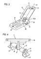
- the invention provides a portable type electronic apparatus including a first casing having a display portion, a second casing having an operating portion, and a hinge portion for rotatably coupling the first casing to the second casing, wherein the hinge portion includes a rotation preventing unit having a first rotating axis to be an axis in a rotation from a state in which the first casing and the second casing are opened to a state in which they are closed to be opposed to each other, and a second rotating axis to be an axis in a rotation of either the first casing or the second casing in an orthogonal direction to a rotating direction of the first rotating axis in a state in which the first casing and the second casing are opened within a predetermined angle range around the first rotating axis, and serving to prevent a rotation of the first casing or the second casing around the second rotating axis in a state in which the first casing and the second casing are opened beyond the predetermined angle range.
- the first casing and the second casing are not rotated around the second rotating axis in the state in which the first casing and the second casing are opened beyond the predetermined angle range. Therefore, it is possible to provide a portable type electronic apparatus capable of stably holding the two casings in an opening state without shaking.
- the invention provides the portable type electronic apparatus, further comprising a call unit for implementing a call function through a radio communication line, a receiver for outputting and receiving a call voice from the call unit being provided in the first casing, a microphone for inputting and transmitting the call voice to the call unit being provided in the second casing or the first casing, and the call unit functioning when the first casing and the second casing are opened with the receiver and the microphone turned in almost identical directions to each other.
- the portable type electronic apparatus in which the casings are stably held without shaking and a transmission/receipt can be carried out in an excellent use condition also in the state in which a user opens the first casing and the second casing at a predetermined angle or more during a call and holds the second casing with the first casing pressed against his (her) ear.
- the invention provides the portable type electronic apparatus, wherein a first image pickup portion accommodating a first image pickup element is provided on a display surface side of a display portion of the first casing, and the display portion has a function of displaying an image picked up by the first image pickup portion.
- an angle formed by the first casing and the second casing is set to be approximately 90 degrees with a rotation around the first rotating axis and the display screen of the display portion is placed into a transversely long position to change over the image display to be transversely long. Consequently, it is possible to provide, to a user, a display which can easily be seen.
- the first casing and the second casing are opened at a predetermined angle or more to carry out a call, moreover, a rotation around the second rotating axis can be prevented by the rotation preventing unit of the hinge portion. Consequently, the casing can be stably held without shaking and the transmission/receipt can be carried out in an excellent use condition.
- the invention provides the portable type electronic apparatus, wherein a second image pickup portion accommodating a second image pickup element is provided in an opposite direction to the first image pickup portion in the first casing, and the display portion has a function of displaying images picked up by the first image pickup portion and the second image pickup portion.
- the display portion of the cell phone displays a transversely long image picked up by the first image pickup portion on a vertically long screen in normal use
- an angle formed by the first casing and the second casing is set to be approximately 90 degrees with a rotation around the first rotating axis. Consequently, it is possible to provide, to a user, a display which can easily be seen.
- the first casing and the second casing are not rotated around the second rotating axis and the first casing and the second casing can be prevented from hitting against the antenna protruded from the casing. Therefore, it is possible to provide a portable terminal device in which the user can carry out a manipulation to give a call without anxiety in a state in which there is no possibility of a breakage.
- the notch portions 34b and 35b according to the first variant have such shapes that the notch portions 34a and 35a in Fig. 5 are extended in a rotating direction in the case in which the second rotating shaft portion 36 is rotated in the axial direction of the first rotating axis 31.
- Fig. 10 is a perspective view showing the external structure of a portable type electronic apparatus according to a second embodiment of the invention.
- a first casing 10 is provided with a first image pickup portion 12 accommodating a first image pickup element for picking up the image of a forward part in an upper part on the display surface side of a display portion 11 and a receiver 13 for outputting and receiving a call voice, and a microphone 14 for inputting and transmitting the call voice in a lower part on the display surface side of the display portion 11 in a main surface portion exposed when opening the first casing 10.
- a second image pickup portion operating key 23 for operating a second image pickup portion (not shown) disposed in the first casing 10 or a second casing 20 is provided in the side surface portion of the second casing 20. In the case in which the second image pickup portion is not provided, however, it is also possible to employ a structure in which the second image pickup portion operating key 23 is not provided or may be usable as the image pickup portion operating key of the first image pickup portion 12.
- Fig. 11 is a plan view showing a structure obtained in the case in which the first casing 10 is rotated around a second rotating axis 32 to set an angle formed by the first casing 10 and the second casing 20 to be approximately 90 degrees in a portable type electronic apparatus according to the first embodiment illustrated in Fig. 1 or the second embodiment illustrated in Fig. 10.
- the first casing 10 is rotated to set the angle formed by the first casing 10 and the second casing 20 to be approximately 90 degrees.
- the fourth embodiment illustrates a variant of the third embodiment shown in Fig. 12.
- the first casing 10 is provided with a second image pickup portion 15 accommodating a second image pickup element for picking up the image of the rear part of a display portion 11 on the base end side of an opposite surface to the display surface (main surface part) of the display portion 11 (a rear face part on an opposite side), that is, in the vicinity of a hinge portion 30.
- an image picked up by the second image pickup portion 15 can be displayed on the display portion 11.
- the second image pickup portion 15 By picking up an image on the opposite side of the display portion 11 by the second image pickup portion 15, therefore, it is possible to pick up an image while confirming the photographed image by utilizing the display screen of the display portion 11 as a monitor like the finder of a camera.
- a position in which the second image pickup portion 15 is to be disposed is set in a rear face portion in an opposite direction to the main surface portion of the first casing 10 (the display surface of the display portion), for example, in the vicinity of a central part, it is possible to obtain the same functions and advantages as those in the third and fourth embodiments.
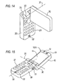
- Fig. 14 is a perspective view showing the external structure of a portable type electronic apparatus according to a fifth embodiment of the invention.
- Fig. 14 shows a structure obtained in the case in which a first casing 10 is rotated around a second rotating axis 32 to set an angle formed by the first casing 10 and a second casing 20 to be approximately 90 degrees in the same manner as in Fig. 11.
- the fifth embodiment illustrates another arrangement and structure of a second image pickup portion according to the first embodiment shown in Fig. 1.
- the second casing 20 is provided with a second image pickup portion 24 accommodating a second image pickup element in one of the side surface parts of a hinge portion 30 which is turned in the direction of a first rotating axis 31.
- the first casing 10 is rotated around the second rotating axis 32 to set the angle formed by the first casing 10 and the second casing 20 to be approximately 90 degrees as shown in Fig. 14, it is possible to pick up the image of the rear part of a display portion 11 by the second image pickup portion 24.
- the display screen of the display portion 11 as a monitor like the finder of a camera, accordingly, it is possible to pick up an image while confirming a photographed image by the second image pickup portion 24.
- Fig. 15 is a perspective view showing the external structure of a portable type electronic apparatus according to a sixth embodiment of the invention.
- the rotation preventing unit implemented in the rotating structure 2 it is possible to prevent the second casing 20 from being rotated around the second rotating axis 32 in a state in which the first casing 10 and the second casing 20 are rotated around the first rotating axis 31 and are thus opened beyond a predetermined angle range. Even if a user holds the second casing 20 by hand in a call and presses the first casing 10 against his (her) ear, consequently, the casing can be held stably without shaking so that a transmission/receipt can be carried out in an excellent use condition.
- Fig. 16 is a perspective view showing the external structure of a portable terminal device according to a seventh embodiment of the invention.
- Fig. 16 shows a state (a second opening state) in which a first casing 10 is rotated and opened around a first rotating axis 31 in a portable terminal device 102 according to the seventh embodiment.
- the portable terminal device 102 includes the first casing 10 having a display portion 11 and a second casing 20 having an operating portion 21, and includes a hinge portion 30 for coupling the first casing 10 to the second casing 20 in such a manner that the first casing 10 and the second casing 20 can be opened and closed through the first rotating axis 31 and the first casing 10 can be rotated around a second rotating axis 32 in an orthogonal direction to the first rotating axis 31.
- the first casing 10 of the portable terminal device 102 is provided with the display portion 11 for carrying out various displays and a receiver 13 for outputting and receiving a call voice in a main surface portion exposed when the casing 10 is opened.
- the side surface portion of the first casing 10 is provided with an external unit connector 16 for connecting an external unit such as an image pickup unit or a light emitting unit.
- the operating portion 21 including a plurality of operating keys and a microphone 22 for inputting and transmitting a call voice are provided in the main surface portion.
- an antenna 25 for transmitting and receiving a communication signal for a radio communication is provided with a protrusion from a base end in the vicinity of the hinge portion 30 in the second casing 20.
- the portable terminal device 102 has a communicating unit such as a radio communicating portion capable of executing a call function through a radio communication line and a voice signal processing portion.
- Fig. 17 is a perspective view showing a state in which the casing is closed in the portable terminal device 102 according to the seventh embodiment.
- the first casing 10 and the second casing 20 are rotated around the first rotating axis 31 in the hinge portion 30, and the first casing 10 and the second casing 20 are opposed to each other and are closed in such a manner that the main surface portions of both of the casings face and overlap each other.
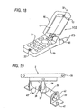
- Fig. 18 is a perspective view showing a state (a first opening state) in which the first casing 10 is rotated around the second rotating axis 32 in the portable terminal device 102 according to the seventh embodiment.
- the first casing 10 is rotatable around the second rotating axis 32 in a state in which the first casing 10 and the second casing 20 are rotated and opened around the first rotating axis 31 within a predetermined angle range. Consequently, in the case in which the display portion 11 in a cell phone displays a transversely long image on a vertically long display screen in normal use, for example, the first casing 10 can be rotated to bring the display screen into a transversely long state.
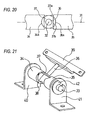
- Fig. 19 is a perspective view showing a state in the first state of a rotating structure 2 provided in the hinge portion 30 in the portable terminal device 102 according to the embodiment.
- Fig. 19 shows, as the first state of the rotating structure 2, a state in which a rotation is carried out around the second rotating axis 32 with the first casing 10 and the second casing 20 opened around the first rotating axis 31 at a predetermined angle.
- the rotation preventing unit is constituted in the rotating structure 2.
- the rotating structure 2 has a first rotating shaft portion 33 to be the center of the rotation of the first rotating axis 31, and a first rotating shaft holder A 34 and a first rotating shaft holder B 35 which serve to hold and fix the first rotating shaft portion 33 and take cylindrical shapes. Moreover, the rotating structure 2 has a second rotating shaft portion 36 to be the center of the rotation of the second rotating axis 32, and an elliptical plate-shaped rotation regulating plate 37 coupled to the second rotating shaft portion 36.
- the rotation regulating plate 37 has the function of being rotated around the first rotating axis 31 together with the second rotating shaft portion 36, and furthermore, being rotated interlockingly with the second rotating shaft portion 36 and preventing the rotation of the second rotating shaft portion 36 around the second rotating axis 32 in a state in which the first casing 10 and the second casing 20 are opened beyond a predetermined angle range.
- a holding plate 38 for holding and fixing the first rotating shaft portion 33 and the second rotating shaft portion 36, a first casing attaching plate 39 for attaching and fixing the tip portion of the second rotating shaft portion 36 to the first casing 10, and a second casing attaching plate A 40 and a second casing attaching plate B 41 which serve to attach and fix both ends of the first rotating shaft portion 33 to the second casing 20 respectively.
- a first rotating shaft snap ring 42 for holding and fixing the first rotating shaft portion 33 to the second casing attaching plate A 40 and the second casing attaching plate B 41 is attached to the second casing attaching plate A 40 and the second casing attaching plate B 41, respectively.
- the first rotating shaft portion 33 has both ends held and fixed to the second casing attaching plate A 40 and the second casing attaching plate B 41 in a state in which the shaft is prevented from coming off by the first rotating shaft snap ring 42. Consequently, the first rotating shaft portion 33 is rotatable around the first rotating axis 31 with respect to the second casing attaching plate A 40 and the second casing attaching plate B 41.
- the first rotating shaft holder A 34 and the first rotating shaft holder B 35 are provided opposite to each other at a predetermined interval with the second rotating shaft portion 36 interposed therebetween in such a manner that the second rotating shaft portion 36 is rotatable around the first rotating axis 31.
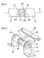
- Arcuate notch portions 34a and 35a are formed on ends at the second rotating shaft portion 36 side in the first rotating shaft holder A 34 and the first rotating shaft holder B 35.
- the notch portions 34a and 35a take external shapes on a slightly larger circumference than the circular arc portion 37a of the rotation regulating plate 37 when they are concentric with the second rotating shaft portion 36.
- the rotation regulating plate 37 is fixed to the second rotating shaft portion 36.
- the rotation regulating plate 37 is rotated together with the second rotating shaft portion 36 interlockingly with the rotation.
- the notch portions 34a and 35a of the first rotating shaft holder A 34 and the first rotating shaft holder B 35 are larger than the circular arc portion 37a of the rotation regulating plate 37.
- the rotation regulating plate 37 can be prevented from hitting against the first rotating shaft holder A 34 and the first rotating shaft holder B 35 to regulate the rotation in the state shown in Fig. 20.
- the second rotating shaft portion 36 can be rotated freely, and the first casing attaching plate 39 is rotated so that the first casing 10 can be rotated around the second rotating axis 32.
- Fig. 21 is a perspective view showing a structure in the second state of the rotating structure 2 according to the embodiment.
- Fig. 21 shows, as the second state of the rotating structure 2, a state in which a rotation around the second rotating axis 32 is regulated in such a condition that the first casing 10 and the second casing 20 in the portable terminal device 102 are opened around the first rotating axis 31 beyond a predetermined angle range as shown in Fig. 16.
- the second rotating shaft portion 36 is further rotated around the first rotating axis 31 in the state shown in Fig. 19 and is inclined with respect to the second casing attaching plate A 40 and the second casing attaching plate B 41.
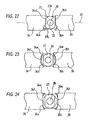
- Fig. 23 is a plan view showing a first variant of the rotating structure according to the embodiment.
- Fig. 23 shows the enlarged structures of the second rotating shaft portion 36, the rotation regulating plate 37, the first rotating shaft holder A 34 and the first rotating shaft holder B 35 seen in the direction of the second rotating axis 32 in the first state of the rotating structure 2 shown in Fig. 19.
- notch portions 34b and 35b having notch ranges expanded are provided in the first rotating shaft holder A 34 and the first rotating shaft holder B 35.
- the notch portions 34b and 35b have slightly larger circular arc portions 34e and 35e than the circular arc portion 37a of the rotation regulating plate 37 and bottom portions 34f and 35f taking external shapes on the tangential lines of the arcs of the circular arc portions 34e and 35e in the same manner as in the structure of Fig. 20.
- the bottom portions 34f and 35f are formed rectilinearly in parallel with the parallel ends 34d and 35d to connect the circular arc portions 34e and 35e at both ends.
- the notch portions 34b and 35b according to the first variant have such shapes that the notch portions 34a and 35a in Fig. 20 are extended in a rotating direction in the case in which the second rotating shaft portion 36 is rotated in the axial direction of the first rotating axis 31.
- the second rotating shaft portion 36 and the rotation regulating plate 37 are positioned within the ranges of the notch portions 34b and 35b of the first rotating shaft holder A 34 and the first rotating shaft holder B 35 as shown in Fig. 23, accordingly, the second rotating shaft portion 36 can be rotated freely without the regulation of a rotation through the rotation regulating plate 37.
- the external shape of the rotation regulating plate 37 abuts on the first rotating shaft holder A 34 and the first rotating shaft holder B 35 so that the rotation of the second rotating shaft portion 36 is regulated.
- the first casing 10 can be rotated around the first rotating axis 31 with respect to the second casing 20 and can be rotated around the second rotating axis 32 in an opening state within a predetermined angle range. In the case in which the predetermined angle range is exceeded, furthermore, it is possible to regulate the rotation around the second rotating axis 32.
- a range in which the first casing 10 can be rotated around the second rotating axis 32 is slightly increased as compared with the structures shown in Figs. 19 to 22.
- Fig. 24 is a plan view showing a second variant of the rotating structure according to the embodiment.
- Fig. 24 shows the enlarged structures of the second rotating shaft portion 36, the rotation regulating plate 37, the first rotating shaft holder A 34 and the first rotating shaft holder B 35 seen in the direction of the second rotating axis 32 in the first state of the rotating structure 2 shown in Fig. 19.
- notch portions 34c and 35c having notch ranges further expanded than those in the first variant in the first rotating shaft holder A 34 and the first rotating shaft holder B 35.
- the notch portions 34c and 35c have the slightly larger circular arc portions 34e and 35e than the circular arc portion 37a of the rotation regulating plate 37, and the bottom portions 34f and 35f taking external shapes on the tangential lines of the arcs of the circular arc portions 34e and 35e in the same manner as in the structure of Fig. 23, and the bottom portions 34f and 35f are formed to have greater lengths than those in Fig. 23.
- the ranges in which the notch portions 34c and 35c are formed are set to take an almost half round of the outer peripheries of the first rotating shaft holder A 34 and the first rotating shaft holder B 35.
- the bottom portions connecting the circular arc portions on both ends in the notch portions provided on the first rotating shaft holder A 34 and the first rotating shaft holder B 35 may be curves other than straight lines in the example shown in the drawings or may take any shape within a range in which the outer peripheral portion of the rotation regulating plate 37 does not abut thereon.
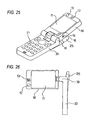
- Fig. 25 is a perspective view showing the external structure of a portable terminal device according to an eighth embodiment of the invention.
- a first casing 10 is provided with a first image pickup portion 12 accommodating a first image pickup element for picking up the image of a forward part in an upper part on the display surface side of a display portion 11 and a receiver 13 for outputting and receiving a call voice, and a microphone 14 for inputting and transmitting the call voice in a lower part on the display surface side of the display portion 11 in a main surface portion exposed when opening the first casing 10.
- Fig. 26 is a plan view showing a structure obtained in the case in which the first casing 10 is rotated around a second rotating axis 32 to set an angle formed by the first casing 10 and a second casing 20 to be approximately 90 degrees in the variant of a portable type electronic apparatus according to the variant of the portable terminal device according to the seventh embodiment illustrated in Fig. 16.
- Fig. 26 shows a variant in which the first image pickup portion 12 is provided on the display surface side of the display portion 11 in the first casing 10 in the structure of Fig. 16.
- a rotating structure 2 provided in a hinge portion 30 for coupling the first casing 10 to the second casing 20 is set in a state in which the external shape of a rotation regulating plate 37 does not hit against a first rotating shaft holder A 34 and a first rotating shaft holder B 35 as shown in Figs. 19 and 20. For this reason, the first casing 10 can be rotated optionally around the second rotating axis 32.
- the first casing 10 is rotated to set the angle formed by the first casing 10 and the second casing 20 to be approximately 90 degrees.
- the first casing 10 and the second casing 20 are rotated around a first rotating axis 31 to bring an opening state beyond a predetermined angle range as shown in Fig. 16 or Fig. 25.
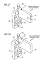
- Fig. 27 is a perspective view showing the external structure of a portable terminal device according to a ninth embodiment of the invention.
- Fig. 27 shows a structure obtained in the case in which a first casing 10 is rotated around a second rotating axis 32 to set an angle formed by the first casing 10 and a second casing 20 to be approximately 90 degrees in the same manner as in Fig. 26.
- the ninth embodiment illustrates an arrangement and structure obtained in the case in which a second image pickup portion is provided in addition to the structure in which the first image pickup portion is provided in Fig. 26.
- the first casing 10 is provided with a second image pickup portion 15 accommodating a second image pickup element for picking up the image of the rear part of a display portion 11 on the tip portion side of an opposite surface to the display surface (main surface part) of the display portion 11 (a rear face part on an opposite side), that is, in the vicinity of the end of the first casing 10.
- the tenth embodiment illustrates a variant of the ninth embodiment shown in Fig. 27.
- the first casing 10 is provided with a second image pickup portion 15 accommodating a second image pickup element for picking up the image of the rear part of a display portion 11 on the base end side of an opposite surface to the display surface (main surface part) of the display portion 11 (a rear face part on an opposite side), that is, in the vicinity of a hinge portion 30.
- an image picked up by the second image pickup portion 15 can be displayed on the display portion 11.
- the second image pickup portion 15 By picking up an image on the opposite side of the display portion 11 by the second image pickup portion 15, therefore, it is possible to pick up an image while confirming the photographed image by utilizing the display screen of the display portion 11 like the finder of a camera.
- a position in which the second image pickup portion 15 is to be disposed is set in a rear face portion in an opposite direction to the main surface portion of the first casing 10 (the display surface of the display portion), for example, in the vicinity of a central part, it is possible to obtain the same functions and advantages as those in the ninth and tenth embodiments.
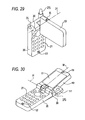
- Fig. 29 is a perspective view showing the external structure of a portable terminal device according to an eleventh embodiment of the invention.
- Fig. 29 shows a structure obtained in the case in which a first casing 10 is rotated around a second rotating axis 32 to set an angle formed by the first casing 10 and a second casing 20 to be approximately 90 degrees in the same manner as in Fig. 26.
- the eleventh embodiment illustrates another arrangement and structure obtained in the case in which a second image pickup portion is provided in addition to the structure in which the first image pickup portion is provided in Fig. 26.
- the second casing 20 is provided with a second image pickup portion 24 accommodating a second image pickup element in one of the side surface parts of a hinge portion 30 which is turned in the direction of a first rotating axis 31.
- the eleventh embodiment in the case in which the first casing 10 is rotated around the second rotating axis 32 to set the angle formed by the first casing 10 and the second casing 20 to be approximately 90 degrees as shown in Fig. 29, it is possible to pick up the image of the rear part of a display portion 11 by the second image pickup portion 24.
- the display screen of the display portion 11 like the finder of a camera, accordingly, it is possible to pick up an image while confirming a photographed image by the second image pickup portion 24.
- the first casing 10 and the second casing 20 are rotated around the first rotating axis 31 to bring an opening state beyond a predetermined angle range as shown in Fig. 16.
- the first casing 10 can be prevented from hitting against an antenna 25 protruded from the second casing 20. Therefore, the antenna 25 or the first casing 10 can be prevented from being damaged so that the user can carry out a manipulation without anxiety and can perform a transmission/receipt in an excellent use condition.
- Fig. 30 is a perspective view showing the external structure of a portable terminal device according to a twelfth embodiment of the invention.
- the twelfth embodiment illustrates a state in which an image pickup unit 51 accommodating an image pickup element is removably connected through an external unit connector 16 to the portable terminal device having no image pickup portion shown in Fig. 16.
- the image pickup unit 51 is attached to the external unit connector 16 provided in the vicinity of a hinge portion 30 in the side surface portion of a first casing 10 in such a state as to be protruded from the first casing 10. Also in the twelfth embodiment, it is possible to prevent the first casing 10 from being rotated around a second rotating axis 32 by a rotation preventing unit implemented by a rotating structure 2 provided in the hinge portion 30 in a state in which the first casing 10 and a second casing 20 are rotated around a first rotating axis 31 and are thus opened beyond a predetermined angle range. Consequently, the first casing 10 or the image pickup unit 51 can be prevented from hitting against an antenna 25 for a communication which is protruded from the second casing 20. Therefore, the antenna 25, the first casing 10 or the image pickup unit 51 can be prevented from being damaged so that a user can carry out a manipulation without anxiety and can perform a transmission/receipt in an excellent use condition.
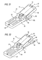
- the light emitting unit 52 is attached to the external unit connector 16 provided in the vicinity of a hinge portion 30 in the side surface portion of a first casing 10 in such a state as to be protruded from the first casing 10. Also in the thirteenth embodiment, it is possible to prevent the first casing 10 from being rotated around a second rotating axis 32 by a rotation preventing unit implemented by a rotating structure 2 provided in the hinge portion 30 in a state in which the first casing 10 and a second casing 20 are rotated around a first rotating axis 31 and are thus opened beyond a predetermined angle range. Consequently, the first casing 10 or the light emitting unit 52 can be prevented from hitting against an antenna 25 for a communication which is protruded from the second casing 20. Therefore, the antenna 25, the first casing 10 or the light emitting unit 52 can be prevented from being damaged so that a user can carry out a manipulation without anxiety and can perform a transmission/receipt in an excellent use condition.
- the fourteenth embodiment it is possible to prevent the first casing 10 from being rotated around a second rotating axis 32 by a rotation preventing unit implemented by a rotating structure 2 provided in a hinge portion 30 in a state in which the first casing 10 and a second casing 20 are rotated around a first rotating axis 31 and are thus opened beyond a predetermined angle range. Also in a state in which an antenna 25 for carrying out a radio communication expands or contracts and expands outward from the second casing 20 in the direction of the first casing 10 as in the structure of Fig. 32, accordingly, the first casing 10 or the light emitting unit 52 can be prevented from hitting against the antenna 25 for a communication which is protruded from the second casing 20. Therefore, the antenna 25, the first casing 10 or the light emitting unit 52 can be prevented from being damaged so that a user can carry out a manipulation without anxiety and can perform a transmission/receipt in an excellent use condition.
- the antenna for a radio communication is provided with a protrusion from the casing, consequently, the antenna can be prevented from hitting against the casing so that the antenna or the casing can be prevented from being damaged.
- the image pickup unit or the light emitting unit is attached as the external unit, moreover, it can be prevented from hitting against the antenna, causing a damage. Accordingly, it is possible to eliminate a possibility that the apparatus might be damaged by the rotation of the casing and to carry out a manipulation without anxiety. Thus, it is possible to provide a portable terminal device capable of maintaining an excellent use condition and enhancing a handling property in use.
- a portable type electronic apparatus comprising a hinge portion having a rotating function in a plurality of directions, wherein in the case in which one of two casings is pressed against an ear at time of a call through a telephone function, the casings can be held stably without shaking in an opening state and a handling property in use can be thus enhanced.
- a portable terminal device comprising a hinge portion having a rotating function in a plurality of directions, wherein in the case in which there is a member to be provided or attached with a protrusion toward the outside of a casing, for example, an antenna for a radio communicating function or an image pickup unit or a light emitting unit for a camera function, the member and the casing can be prevented from being damaged by the rotation of the casing so that a user can carry out a manipulation without anxiety and a handling property in use can be enhanced.
Landscapes
- Engineering & Computer Science (AREA)
- General Engineering & Computer Science (AREA)
- Mechanical Engineering (AREA)
- Signal Processing (AREA)
- Telephone Set Structure (AREA)
- Studio Devices (AREA)
Priority Applications (1)
| Application Number | Priority Date | Filing Date | Title |
|---|---|---|---|
| EP05024838A EP1645759A1 (fr) | 2002-10-15 | 2003-10-15 | Appareil électronique portatable pliable et rotatif |
Applications Claiming Priority (5)
| Application Number | Priority Date | Filing Date | Title |
|---|---|---|---|
| JP2002300687 | 2002-10-15 | ||
| JP2002300686A JP2004138092A (ja) | 2002-10-15 | 2002-10-15 | 携帯型電子機器 |
| JP2002300687A JP2004140439A (ja) | 2002-10-15 | 2002-10-15 | 携帯端末装置 |
| JP2002300686 | 2002-10-15 | ||
| PCT/JP2003/013201 WO2004036069A1 (fr) | 2002-10-15 | 2003-10-15 | Appareil electronique portatif |
Related Child Applications (1)
| Application Number | Title | Priority Date | Filing Date |
|---|---|---|---|
| EP05024838A Division EP1645759A1 (fr) | 2002-10-15 | 2003-10-15 | Appareil électronique portatable pliable et rotatif |
Publications (2)
| Publication Number | Publication Date |
|---|---|
| EP1553314A1 true EP1553314A1 (fr) | 2005-07-13 |
| EP1553314A4 EP1553314A4 (fr) | 2006-04-26 |
Family
ID=32109452
Family Applications (2)
| Application Number | Title | Priority Date | Filing Date |
|---|---|---|---|
| EP03769902A Withdrawn EP1553314A4 (fr) | 2002-10-15 | 2003-10-15 | Appareil electronique portatif |
| EP05024838A Withdrawn EP1645759A1 (fr) | 2002-10-15 | 2003-10-15 | Appareil électronique portatable pliable et rotatif |
Family Applications After (1)
| Application Number | Title | Priority Date | Filing Date |
|---|---|---|---|
| EP05024838A Withdrawn EP1645759A1 (fr) | 2002-10-15 | 2003-10-15 | Appareil électronique portatable pliable et rotatif |
Country Status (4)
| Country | Link |
|---|---|
| US (1) | US20070097611A1 (fr) |
| EP (2) | EP1553314A4 (fr) |
| AU (1) | AU2003280560A1 (fr) |
| WO (1) | WO2004036069A1 (fr) |
Cited By (2)
| Publication number | Priority date | Publication date | Assignee | Title |
|---|---|---|---|---|
| EP1967748A4 (fr) * | 2005-12-27 | 2012-10-24 | Mitsubishi Steel Mfg | Dispositif d articulation a deux axes avec fonction de regulation de rotation |
| US20200082176A1 (en) * | 2018-09-12 | 2020-03-12 | Toyota Motor Engineering & Manufacturing North America, Inc. | Systems and methods for extending detachable automobile sensor capabilities for identification of selected object types |
Families Citing this family (8)
| Publication number | Priority date | Publication date | Assignee | Title |
|---|---|---|---|---|
| JP4778207B2 (ja) | 2004-06-08 | 2011-09-21 | 日本電気株式会社 | ヒンジ機構及びそれを組み込んだ電子機器、その組み立て方法 |
| KR100640395B1 (ko) | 2004-08-28 | 2006-10-30 | 삼성전자주식회사 | 휴대 단말기의 이축 힌지 장치 및 그의 장착 메카니즘 |
| TWI322625B (en) * | 2006-07-17 | 2010-03-21 | Fortemedia Inc | Electronic device capable of receiving sound in different mode via external microphone and sound-receiving method |
| JP4730270B2 (ja) * | 2006-09-28 | 2011-07-20 | 富士フイルム株式会社 | 携帯機器 |
| JP4695627B2 (ja) * | 2007-07-02 | 2011-06-08 | 富士通株式会社 | 電子機器および受け部材 |
| JP2010098658A (ja) * | 2008-10-20 | 2010-04-30 | Panasonic Corp | 折り畳み式携帯電子機器 |
| CN104185824B (zh) * | 2012-03-31 | 2019-01-22 | 英特尔公司 | 用于显示和集成的投影的计算设备、装置和系统 |
| CN105988519A (zh) * | 2015-02-16 | 2016-10-05 | 联想(北京)有限公司 | 电子设备 |
Family Cites Families (13)
| Publication number | Priority date | Publication date | Assignee | Title |
|---|---|---|---|---|
| JPH05204487A (ja) * | 1992-01-28 | 1993-08-13 | Hitachi Ltd | 情報処理装置 |
| US5335142A (en) * | 1992-12-21 | 1994-08-02 | Ast Research, Inc. | Portable computer display tilt/swivel mechanism |
| EP0658938B1 (fr) * | 1993-12-15 | 2001-08-08 | STMicroelectronics S.r.l. | Circuit intégré comprenant une cellule EEPROM et un transistor MOS |
| JP3467362B2 (ja) * | 1996-01-08 | 2003-11-17 | 富士通株式会社 | 情報処理装置 |
| JP3037217B2 (ja) * | 1997-07-08 | 2000-04-24 | 埼玉日本電気株式会社 | 折り畳み式携帯型電子機器 |
| JP3360016B2 (ja) * | 1998-03-03 | 2002-12-24 | 三菱製鋼株式会社 | ヒンジ装置 |
| JP3031903B1 (ja) * | 1998-12-25 | 2000-04-10 | 三菱製鋼株式会社 | ヒンジ機構 |
| JP3546784B2 (ja) * | 1999-12-14 | 2004-07-28 | 日本電気株式会社 | 携帯端末 |
| JP2001298513A (ja) * | 2000-04-12 | 2001-10-26 | Matsushita Electric Ind Co Ltd | 携帯型無線通信装置 |
| JP2002158758A (ja) * | 2000-11-20 | 2002-05-31 | Nec Corp | 開閉型携帯情報端末 |
| JP2002246819A (ja) * | 2001-02-16 | 2002-08-30 | Hitachi Ltd | 携帯電話 |
| JP3634278B2 (ja) * | 2001-03-12 | 2005-03-30 | 株式会社ストロベリーコーポレーション | 二軸ヒンジ装置 |
| JP4288038B2 (ja) * | 2002-03-06 | 2009-07-01 | 京セラ株式会社 | 携帯端末機器 |
-
2003
- 2003-10-15 EP EP03769902A patent/EP1553314A4/fr not_active Withdrawn
- 2003-10-15 AU AU2003280560A patent/AU2003280560A1/en not_active Abandoned
- 2003-10-15 US US10/531,437 patent/US20070097611A1/en not_active Abandoned
- 2003-10-15 WO PCT/JP2003/013201 patent/WO2004036069A1/fr not_active Ceased
- 2003-10-15 EP EP05024838A patent/EP1645759A1/fr not_active Withdrawn
Cited By (2)
| Publication number | Priority date | Publication date | Assignee | Title |
|---|---|---|---|---|
| EP1967748A4 (fr) * | 2005-12-27 | 2012-10-24 | Mitsubishi Steel Mfg | Dispositif d articulation a deux axes avec fonction de regulation de rotation |
| US20200082176A1 (en) * | 2018-09-12 | 2020-03-12 | Toyota Motor Engineering & Manufacturing North America, Inc. | Systems and methods for extending detachable automobile sensor capabilities for identification of selected object types |
Also Published As
| Publication number | Publication date |
|---|---|
| EP1553314A4 (fr) | 2006-04-26 |
| AU2003280560A1 (en) | 2004-05-04 |
| US20070097611A1 (en) | 2007-05-03 |
| WO2004036069A1 (fr) | 2004-04-29 |
| EP1645759A1 (fr) | 2006-04-12 |
Similar Documents
| Publication | Publication Date | Title |
|---|---|---|
| JP4234379B2 (ja) | 折り畳み型端末機のヒンジ装置および折り畳み型端末機 | |
| JP3882687B2 (ja) | 携帯型通信装置 | |
| US20040209645A1 (en) | Portable terminal | |
| KR100524532B1 (ko) | 휴대전화기 | |
| EP1653713B1 (fr) | Terminal de communication portable et pliable | |
| US20030109232A1 (en) | Camera lens mounting device of folder type telephone | |
| US7043284B2 (en) | Integrated cellular phone, digital camera, and PDA, with swivel mechanism providing access to the interface elements of each function | |
| US20070270199A1 (en) | Watch type mobile phone | |
| EP1411707A1 (fr) | Appareil de communication portable avec une partie pliante rotative dans deux directions | |
| KR20040077522A (ko) | 폴더형 카메라장치 및 폴더형 휴대전화기 | |
| EP1645759A1 (fr) | Appareil électronique portatable pliable et rotatif | |
| US20060116157A1 (en) | Portable type electronic apparatus | |
| EP1630331A2 (fr) | Charnière biaxiale pour terminal portable et mécanisme de montage | |
| KR100461769B1 (ko) | 외장형 카메라 렌즈 모듈이 장착된 스타일러스 및 이를채용한 무선 단말기 | |
| JP2004138092A (ja) | 携帯型電子機器 | |
| JP2010136388A (ja) | 携帯情報端末用ディジタルカメラ及びディジタルカメラシステム | |
| EP1489835A1 (fr) | Appareil pliable et portable avec une caméra | |
| JP2004029559A (ja) | 電子機器用クレードル装置 | |
| JP2004140439A (ja) | 携帯端末装置 | |
| KR100790089B1 (ko) | 스토퍼 장치를 구비한 휴대 단말기 | |
| KR100474037B1 (ko) | 회전형 카메라가 장착된 휴대폰 | |
| KR20040056581A (ko) | 휴대용 무선단말기의 카메라 렌즈 어셈블리를 구비한안테나 장치 | |
| WO2005114807A1 (fr) | Téléphone cellulaire intégré, appareil photographique numérique, et pda, avec mécanisme de permutation donnant accès aux éléments d'interface de chaque fonction | |
| KR20040066514A (ko) | 손잡이를 구비한 휴대용 무선단말기 | |
| KR20050029617A (ko) | 탈착식 lcd모듈이 장착된 휴대폰 |
Legal Events
| Date | Code | Title | Description |
|---|---|---|---|
| PUAI | Public reference made under article 153(3) epc to a published international application that has entered the european phase |
Free format text: ORIGINAL CODE: 0009012 |
|
| 17P | Request for examination filed |
Effective date: 20050414 |
|
| AK | Designated contracting states |
Kind code of ref document: A1 Designated state(s): AT BE BG CH CY CZ DE DK EE ES FI FR GB GR HU IE IT LI LU MC NL PT RO SE SI SK TR |
|
| AX | Request for extension of the european patent |
Extension state: AL LT LV MK |
|
| DAX | Request for extension of the european patent (deleted) | ||
| RBV | Designated contracting states (corrected) |
Designated state(s): DE FR GB |
|
| A4 | Supplementary search report drawn up and despatched |
Effective date: 20060309 |
|
| 17Q | First examination report despatched |
Effective date: 20060727 |
|
| 17Q | First examination report despatched |
Effective date: 20060727 |
|
| RIN1 | Information on inventor provided before grant (corrected) |
Inventor name: YANAGIBASHI, HIDEHIRO Inventor name: KAMATA, MUNEOKI Inventor name: NANMOKU, TERUO Inventor name: NISHIKAWA, KENICHI,4-23-20, ROKKAKUBASHI Inventor name: KOSUGI, SATOSHI, Inventor name: SATO, TAKESHI Inventor name: SATO, KAZUNORI, Inventor name: SATO, NORIYOSHI,133-6, SHINYOSHIDA-CHO Inventor name: TAKAMORI, KAZUAKI |
|
| GRAP | Despatch of communication of intention to grant a patent |
Free format text: ORIGINAL CODE: EPIDOSNIGR1 |
|
| STAA | Information on the status of an ep patent application or granted ep patent |
Free format text: STATUS: THE APPLICATION IS DEEMED TO BE WITHDRAWN |
|
| 18D | Application deemed to be withdrawn |
Effective date: 20080501 |