EP1553348A2 - Household apparatus, especially a cooking apparatus - Google Patents
Household apparatus, especially a cooking apparatus Download PDFInfo
- Publication number
- EP1553348A2 EP1553348A2 EP04002458A EP04002458A EP1553348A2 EP 1553348 A2 EP1553348 A2 EP 1553348A2 EP 04002458 A EP04002458 A EP 04002458A EP 04002458 A EP04002458 A EP 04002458A EP 1553348 A2 EP1553348 A2 EP 1553348A2
- Authority
- EP
- European Patent Office
- Prior art keywords
- household appliance
- appliance according
- muffle
- pull
- side wall
- Prior art date
- Legal status (The legal status is an assumption and is not a legal conclusion. Google has not performed a legal analysis and makes no representation as to the accuracy of the status listed.)
- Withdrawn
Links
- 238000010411 cooking Methods 0.000 title claims abstract description 29
- 238000003780 insertion Methods 0.000 claims abstract description 30
- 230000037431 insertion Effects 0.000 claims abstract description 30
- 238000000605 extraction Methods 0.000 claims description 10
- 229910000831 Steel Inorganic materials 0.000 description 9
- 239000010959 steel Substances 0.000 description 9
- 238000004519 manufacturing process Methods 0.000 description 6
- 238000005516 engineering process Methods 0.000 description 4
- 230000013011 mating Effects 0.000 description 4
- 210000003298 dental enamel Anatomy 0.000 description 3
- 239000011343 solid material Substances 0.000 description 3
- 238000009434 installation Methods 0.000 description 2
- 238000012986 modification Methods 0.000 description 2
- 230000004048 modification Effects 0.000 description 2
- 230000007704 transition Effects 0.000 description 2
- 206010023230 Joint stiffness Diseases 0.000 description 1
- 230000009286 beneficial effect Effects 0.000 description 1
- 238000011109 contamination Methods 0.000 description 1
- 238000004049 embossing Methods 0.000 description 1
- 230000017525 heat dissipation Effects 0.000 description 1
- 239000011796 hollow space material Substances 0.000 description 1
- 239000000463 material Substances 0.000 description 1
- 239000002184 metal Substances 0.000 description 1
- 230000002093 peripheral effect Effects 0.000 description 1
- 230000035882 stress Effects 0.000 description 1
- 230000008646 thermal stress Effects 0.000 description 1
Images



Classifications
-
- F—MECHANICAL ENGINEERING; LIGHTING; HEATING; WEAPONS; BLASTING
- F24—HEATING; RANGES; VENTILATING
- F24C—DOMESTIC STOVES OR RANGES ; DETAILS OF DOMESTIC STOVES OR RANGES, OF GENERAL APPLICATION
- F24C15/00—Details
- F24C15/16—Shelves, racks or trays inside ovens; Supports therefor
- F24C15/168—Shelves, racks or trays inside ovens; Supports therefor with telescopic rail systems
-
- F—MECHANICAL ENGINEERING; LIGHTING; HEATING; WEAPONS; BLASTING
- F25—REFRIGERATION OR COOLING; COMBINED HEATING AND REFRIGERATION SYSTEMS; HEAT PUMP SYSTEMS; MANUFACTURE OR STORAGE OF ICE; LIQUEFACTION SOLIDIFICATION OF GASES
- F25D—REFRIGERATORS; COLD ROOMS; ICE-BOXES; COOLING OR FREEZING APPARATUS NOT OTHERWISE PROVIDED FOR
- F25D23/00—General constructional features
- F25D23/06—Walls
- F25D23/065—Details
- F25D23/067—Supporting elements
Definitions
- the invention relates to household appliance, in particular cooking appliance with a device muffle, to their opposite side walls corresponding lateral extension systems are provided, which in a horizontal Garraumebene each one insertion part support and each one supported on one of the side walls stationary rail exhibit.
- the object of the invention is a household appliance, in particular cooking appliance with a Garrisonmuffel provide with extract systems that are stably supported.
- the object is by a household appliance, in particular cooking appliance with the characteristics of Claim 1 solved.
- the characterizing part of claim 1 is the fixed rail of the pull-out system on two different muffle walls supported. Compared to a holder of the pull-out system on only one muffle wall can tilting moments are reduced according to the invention, which depends on the holding elements of the Extract system be exercised. Such tilting moments are caused by the weight the food support carried on the pull-out systems.
- the pull-out system can be used as be formed a telescopic extension, in addition to the fixed rail, a movable Rail, which optionally via an intermediate rail on the stationary Rail is guided.
- the pull-out system in addition to the fixed Rail having a carriage or a runner on the stationary rail is slidably mounted.
- one of the muffle walls has a side wall and / or a rear wall is.
- the holder of the pull-out system on the muffle side wall allows for easy Accessibility for mounting or dismounting the pull-out system.
- the pull-out system can easily be held by the Front Muffelö réelle be performed up to the muffle back wall.
- the extension system in the manner of a floating bearing in a muffle knewe Insert mounting hole.
- the floating bearing can cause thermal stresses be easily balanced in the pull-out system.
- the pull-out system both on a Sidewall as well as on the back wall of the muffle is held. That's it Pull-out system significantly more resistant to a tilting moment and at the same time easy for the user to install or to solve.
- an actuating element can be provided which in one Locking position of the pull-out system insoluble on the muffelwand constitutionalen Holding element stops. Due to the permanent holder is an accidental unhooking of the Pull-out system reliably prevented by the muffle wall-side holding element. On the other hand, the extension system can be easily solved when the actuator off brought his locking position.
- the adjusting element is designed as a spring element.
- the actuator can automatically in its locking position being held. An accidental release of the extension system of the holder element is therefore almost impossible.
- the actuator in a Unlocking a simple unhooking of the extract system of the Allow holding element.
- a recess for example in the form of a groove or annular groove, be formed, in which the pull-out system can be hung.
- the Pull-out system is thus also in the exercise of shear forces in an axial direction the retaining element securely held.
- the actuator may be supported on the extension system.
- the Muffle side walls thus do not need to be complex in terms of production technology for fastening be adapted to the actuating element.
- the actuator can in his Locking position be directly or almost in contact with the holding element.
- the extension system is almost free of play or wobble in the holding element hooked.
- the Pull-out system is formed with an adapter, preferably hook-shaped is formed or a hollow cylindrical recess for hanging in the Has holding element. It is particularly easy to manufacture, the Recess as a hole, in particular slot in the adapter form.
- the Slot can keyhole-like formed with an extended insertion be. By means of this insertion section, the retaining element can first be hung when hanging be guided. Subsequently, the holding element in a narrow portion of the Long holes are guided, which can engage behind the retaining element accordingly.
- the actuator, the recess for hanging in the Holding element at least partially overlapped.
- the actuator, the recess for hanging in the Holding element at least partially overlapped.
- the stationary rail of the extension system via a so connected adapter can be mounted in the holding element. If the adapter is the Retaining element engages behind, is an accidental pulling out of the extension system in Transverse direction to the side wall prevented.
- the danger of accidental detachment the extraction system is in particular when the extract system from the Muffle opening is partially pulled out. In this case, an impact force in Transverse direction are exerted on the extension system. With a detachable Locking connection of the extension system with the holding element could such impact force decouple the extension system from the retaining element.
- the recess and / or the recess may be in the adapter Be provided actuator.
- the recess and the actuator in be formed an additional part, without the extract system itself adapt.
- Adapter as an angled profile part from eg. Form a steel sheet.
- Adapters For a simple hooking and for easy operation of the actuating element of the Adapters have a spaced from the extension system retaining flange. At this the recess for hanging and / or the adjusting element can be provided. Further the retaining flange of the adapter can be in contact with the muffle side wall. Such If possible large-scale system supports a stable and wobble-free mount of the pull-out system.
- the actuator may be an actuating portion for adjusting between the Have unlocking and locking position.
- This will be a manual Simplified actuation of the actuating element.
- the actuating portion of the actuating element transverse to Excerpt system is arranged offset. It is optically advantageous if the Operating portion of the actuating element is arranged below the extension system. In this case, the actuating portion of the actuating element is optically less visible.
- a safe hooking in the retaining element can be ensured if in the Retaining element is formed a recess, the extraction system, if necessary engages positively behind.
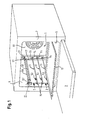
- FIG 1 is a cooking appliance with an inside provided with an enamel layer Cooking appliance muffle 1 shown.
- the cooking appliance has a hinged door 3 for closing a front muffle opening 5.
- the swing door 3 is in the closed state in Installation with a muffle opening 5 pulling front flange 7.
- To the opposite side walls 9 of Garausmuffel 1 are corresponding lateral guide elements 11 and a later described extract system, consisting of two pull-out systems.
- the extension systems 59 are in the Figure 1 held in a top of four horizontal Garraumebenen.
- In the The following three lower Garraumebenen are each the lateral guide elements eleventh supported.
- Based on the two corresponding lowermost guide elements 11 a baking tray 13 from which is partially pushed out of the cooking appliance muffle 1.
- Each of the guide elements 11 is as a rod-shaped steel profile part or manufacturing part formed, which has a circular cross-section and made of a solid material consists.
- the guide elements 11 and / or the pull-out systems can be used by a user in can be arranged in the cooking appliance muffle 1 any way.
- These are the Guide elements 11 and pull-out systems are mufflefront colour each in a Bearing bush formed holding member 15 inserted or mounted.
- a muffle rear wall 17 In the area a muffle rear wall 17 are the guide elements 11 each in a mounting opening 19 a wall member 21 stored. Both the guide elements 11 and the Pull-out systems must be released from the muffle 1 by the user without tools.
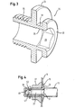
- the muffle front side mounting of the guide elements 11 in the bearing bushes 15 is in of Figure 2 shown in detail. Accordingly, in the figure 3 as a single part shown bearing bush 15 hollow cylindrical with an outer edge flange 23rd educated. This is supported inside a cooking chamber of the muffle 1 inside on the Muffle side wall 9 from.
- the muffle side wall 9 consists of a thin steel sheet with a wall thickness in the range 0.3 to 0.7 mm.
- the edge flange 23 of the bearing bush 15 is garraumayne character in one Insertion cylinder 25 via.
- the insertion cylinder 25 serves as an insertion aid for a Bearing pin 27, which at a rod end of the rod-shaped guide member 11th is trained.
- a hexagon socket provided to with an appropriate tool the Bearing bush 15 to be able to mount in an opening 10 of the muffle side wall 9.
- a the cooking chamber 25 facing insertion opening of the bearing bush 15 is of a Front flange 31 moved frontally.
- the front flange 31 of the bearing bush 15 is from Edge flange 23 axially spaced. In between is a return in the form of an annular groove 33 trained. This serves as later described as a support portion for Mounting the pull-out systems.
- the bearing bush 15 is provided on the outer circumference with an external thread 35, via that the bearing bush according to the figure 2 is screwed into the muffle side wall 9.
- corresponding mating thread 39 is not in the thin-walled Muffle side wall 9 self-formed. Rather, the mating thread 39 in one Secured element 37 is formed.
- the securing element 37 is shown in FIG. 2 on the outside with the muffle side wall 9 in Appendix. It is used as an elongated profile part formed the corresponding mating threads 39 for the bushings 15.
- the Profile member 17 is a cross-sectionally U-shaped steel sheet, which also at thermal load remains torsionally rigid and dimensionally stable.
- Each of the mating threads 39 is incorporated in the manner of a metal nut in the profile part 37.
- the profile part 37 extends in a vertical direction over all bushings shown in Figure 1 15 of a muffle side wall 9. Due to the large-scale investment of the profile part 37 at the Outside the side wall 9, the bushings 15 are stable against tilting moments fastened, despite the thin-walled muffle side wall 9. Approximately midway between the two legs of the U-shaped security element 37 are the Counter thread 39 formed.
- the bushing 15 is with its external thread 35 with a game through the opening 10th the muffle side wall 9 out.
- the bushing 15 is therefore not directly with the Muffle side wall 9 bolted. Rather, the muffle side wall 9 between the Secured securing element 37 and the edge flange 23 of the bearing bush 15.
- the bearing pin 27 of the guide member 11 on reduces a diameter of a positive storage in the bearing bush 15th allowed. As a result, a play-free mounting of the guide member 11 in the Bushing 15 reached. This is further supported by a contact shoulder 51 of the Bearing pin 27 which is in contact with the front flange 31 of the bearing bush 15.
- the bearing bush 15 is shown in a modification. In contrast to the bearing bush shown in Figure 3 is in the bearing bush of Figure 4 on the Front flange 31 omitted.
- the bushing 15 therefore has garrauminnen picture only the edge flange 23.
- the abutment shoulder 51 in corresponding manner pressed against the edge flange 23 of the bearing pin 27.
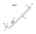
- FIG. 5 shows a guide element 11 removed from the cooking appliance muffle 1 shown.
- the bearing pin 27 is connected to a rod end of the guide member 11 with formed a reduced diameter. Since the guide element 11 of a Solid material consists, manufacturing technology easy, such as by means of a lathe the bearing bolts 27 are formed on the rod end. The with the bearing pin 27th provided rod end of the guide member 11 is also bent angularly. A For this necessary Biegeformung is compared to a hollow material in the here used solid material manufacturing technology easily feasible.
- the guide elements 11 and pull-out systems are each independent of each other formed and inserted into the muffle 1, as can be seen from the figure 1. Consequently, they can also be taken independently of each other from the oven unless they are needed to hold a food support. Thereby can thermally advantageous material entry into the cooking appliance muffle 1 possible be kept low.
- the L-shaped guide member 11 is provided with a along the Muffel side wall 9 elongated legs formed, the leadership and Support of insertion parts is used.
- the L-shape of the guide member 11 allows it, the guide member 11 with its muffle back rod end 54 at the Muffle back wall 17 and with the bent muffle front side bar end at the Muffle side wall 9 to hold. Through this bracket on two different Muffle walls, the guide member 11 is more resistant to tilting moments.
- Muffle front side is on the guide member 11, a height stop 53 as a tilt protection for Insertion parts provided.
- This one is as a curved steel wire hanger with its two Ends pressed into corresponding holes of the guide member 11.
- Corresponding is in the region of the muffle back rod end 54 offset by 90 ° another hole formed in the guide element 11.
- a steel pin is pressed in as a Slide-in stop 55 is used for an insertion part.
- FIG. 6 shows an alternative use of the bearing bush 15.
- the telescopic extension with a holding plate or an adapter 57 is formed in the Ring groove 33 of the bearing bush 15 is mounted.
- the adapter 57 is attached to a stationary Rail 58 of the extension system, for example, spot-welded.
- a rear pin 61 for mounting on the Muffelschreibwand 17 is formed, as shown in Figure 1.
- the pin 61 is like that rear rod end 54 of the guide elements 11 is formed.
- the figure 1 is on the stationary rail 58 via ball bearings, not shown, a movable rail 59th stored. On the movable rail 59, a food support can be supported.
- the muffle front side holding plate 57 is as a steel sheet with a punched slot 63 trained.
- the slot 63 extends perpendicular to the elongated Telescopic extension 59 and serves to hook the retaining plate 57 in the annular groove 33 of Bearing bush 15.
- the slot 63 as an inverted keyhole with a widened insertion portion 65 and a narrow securing portion 67 in FIG the holding plate 57 punched.
- the diameter of the expanded insertion portion 65 is larger than the diameter of the front flange 31 of the bushing 15. Accordingly can the support plate 57 is simply guided over the front flange 31 of the bearing bush 15 and be hung in the annular groove 33.
- the wall thickness of the holding plate 57 is smaller as a groove width of the annular groove 33 of the bearing bush 15.
- the opposite lateral Limiting edges of the securing portion 67 are in the figure 6 within the Ring groove 33 of the bearing bush 15 is arranged. This is an axial movement of the hinged holding plate 57 along the bearing bush 15 prevented.
- a leaf spring 69 by means of a rivet 71 with the Rivet plate 57 riveted.
- the leaf spring 69 acts like a locking element.
- the leaf spring 69 shown in its locking position. In this position is an upper one Locking edge 73 of the leaf spring 69 in abutment with a circumference of the front flange 31 of the bushing 15 or slightly spaced therefrom. An accidental Movement of the holding plate 57 upwards is thus prevented by the leaf spring 69. Accordingly, therefore, an accidental release of the holding plate 57 of the Bearing bush 15 prevented.
- the leaf spring 69 has according to the figure 6 an actuating portion 75. This one can be pressed in the direction of the arrow shown, whereby the locking edge 73rd is pivoted in the direction of the arrow shown in the cooking chamber. In this position is the locking edge 73 of the leaf spring 69 out of engagement with the bearing bush 15. Die Holding plate 57 of the extension system 59 can therefore for a removal of the Excerpt system 59 are raised, so that the bearing bush 15 from the Insertion section 65 of the holding plate 57 can be led out.
- the leaf spring 69 When removed telescopic extension 59, the leaf spring 69 is with her Locking edge 73 directly on the holding plate 57 and overlaps the insertion section 65th of the slot 63.
- the Bearing bush 15 For a renewed hanging of the telescopic extension 59 is the Bearing bush 15 through the slot insertion section 65 of the support plate 57 to lead. On In this way, the bearing bush 15 presses the leaf spring 69 with its locking edge 73rd away from the holding plate 57.
- the telescopic extension 59 can be slightly lowered by the user, until the bushing 15 in the narrow securing portion 67 of the slot 63rd is as shown in Figure 6.
- the leaf spring 69 automatically jumped back into its locking position.
- the leaf spring 69 can only be tilted from the locking position to an unlocking position when a User presses on their operating section 75.
- the Holding plate 57 of the telescopic extension 59 are slightly raised by the user.
- the bearing bush 15 is arranged in the insertion section 65 of the elongated hole 63.
- the holding plate 59 by an axial movement of the bearing bush 15 are solved.
- Figures 7 and 8 are concerned with the storage of the rod-shaped guide member 11 and the journal 61 of the extension system 59 on the rear side wall of the Cooking appliance muffle 1.
- this is garraumayne paragraph each side one Wall element 21 arranged with corresponding mounting holes 19.
- the guide elements 11 and the pullout systems 59 after Type of a floating bearing stored. That is, that the respective rod end or the Can move trunnion 61 in a depth direction and thus heat-related Voltages are avoided.
- the wall element 21 is shown in FIG. 8 as a angled U-profile part made of a steel sheet with a large heat-resistant Stiffness trained.
- the U-profile part 21 has a leg at its one at right angles bent abutment flange 77. This is about locking screws 79th large area in plant with a mounting surface of a muffle back wall side Air guide plate 81 mounted.
- the air guide plate 81 separates a not shown Ring radiator and a fan from the oven. Through this assembly at the Air guide plate 81 is achieved that no additional openings for attachment of the U-profile part 81, for the storage of the extension system 59 or for storage of the Guide element 11 must be formed in the muffle back wall 17.
- the back Side wall of Garellamuffel 1 consists according to the figures 7 and 8 of the Muffle back wall 17, the air guide plate 81 and the garrauminnen remedyen Wall elements 21.
- the angled U-profile part 21 also has a mounting flange 83. This is offset relative to the abutment flange 77 in the direction of the cooking chamber.
- Mounting flange 83 are in a vertical row, the mounting holes 19 for the Guiding elements 11 and formed for the bearing pin 61 of the extension system 59.
- each of the assembly openings 19 moves a cup-like edge embossing or a collar 85 which projects into the cooking chamber.
- This Collar 85 serves as a butt edge during the insertion of the journal 61 and the Stabendes 54.
- an additional diaphragm 87 is provided on the wall element 21 set to shield the U-profile part 21 relative to the cooking chamber.
- the aperture 87 designed as a U-shaped sheet steel profile part, the corresponding to the mounting holes 19 of the U-profile part 21 apertures 89th having. Their diameter is made slightly larger than the diameter of the Collar 85 of the mounting opening 19.
- the cup-shaped collar 85 protrudes in the mounted Condition according to the figure 7 through the aperture 89 in the oven.
- the collar 85 can function as an insertion aid for the Bearing 61 and the rod end 54 meet.
- the cooking chamber facing surface of the aperture 87 is corresponding to the Muffle walls surface-treated, d. H. in the present case with an enamel layer Mistake.
- the aperture 87 occurs optically together with the wall element 23 largely in the background.
- the aperture 87 is not directly in contact with the air guide plate 81. Rather, the aperture is small, d. H. at least non-contact of the Air guide plate 81 spaced. Corresponding damage to the enamel layer the air guide plate 81 through the aperture 87 can be avoided.
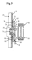
- FIG. 9 The second embodiment shown in FIG. 9 is essentially identical to FIG the first embodiment of Figures 1 to 8.
- the holder member 15 is formed as a support bolt 15 is, which is screwed into the mounting hole 10 of the muffle side wall 9.
- the Support bolt 15 is identical except for the insertion opening 25 with the Bearing bush 15 of the first embodiment. It can therefore only the Telescopic extension with its adapter 57 are suspended in the support pin 15. Inserting a guide element 11, however, is not possible.
- the stationary lower rail 58 is U-shaped. Within the stationary lower rail 58 is mounted an intermediate rail. This connects via indicated ball bearing the stationary lower rail 58 with the movable upper Rail 59. On a side leg of the fixed rail 58 is the adapter 57th welded. The adapter 57 is with its keyhole-like slot 63 in the Retaining pin 15 mounted. In this case, the adapter 57 is suspended in the annular groove 33 and engages behind the front flange 31 of the support pin 15. The telescopic extension can so that it is not accidentally pulled in the axial direction of the support pin 15.
- the leaf spring 69 shown in Figure 9 is shown in its locking position. In this position is the leaf spring 69 with its locking edge 73 almost in contact with the front flange 31 of the support bolt 15. The telescopic extension is therefore in the Locking position of the leaf spring 69 almost free of play and unsolvable with the Bracket pin 15 connected.
- the leaf spring 69 is connected to the adapter 57 riveted. In this case, the leaf spring 69 overlaps the expanded portion 65 of the Langloches 63.
- the support pin 15 When attaching the telescopic extension of the muffle side wall 9 is First, the support pin 15 through the extended portion 65 of the elongated hole 63 to lead until the adapter 57 abuts the edge flange 23 of the support bolt. In this case, the support pin 15 presses the leaf spring 69 in its unlocked position.
- the leaf spring 69 is over their Operating portion 75 is pressed in its unlocked position.
- the operating section 75 is arranged for easy access below the stationary rail 58. Then the telescopic extension can be raised until the Support bolt 15 is located in the expanded portion 65 of the slot 63. In this position, the adapter 57 of the telescopic extension simply from the mounting bolts 15 are pulled.
- the adapter 57 is provided with a retaining flange 71 trained.
- the retaining flange 71 is in contact with its beaded peripheral edge 72 with the muffle side wall 9. This is a stable and wobble-free mounting of Telescopic extension supported on the muffle wall 9.
- the slot 63 is formed for hanging.
- Between the retaining flange 71 of the adapter 57 and the muffle side wall 9 is a largely separated from the cooking space mounting gap 73 trained.
- the provided in the gap 73 edge flange 23 of the support pin or the bearing pin 15 is therefore largely from contamination from the oven protected.
Landscapes
- Engineering & Computer Science (AREA)
- Chemical & Material Sciences (AREA)
- Combustion & Propulsion (AREA)
- Mechanical Engineering (AREA)
- General Engineering & Computer Science (AREA)
- Baking, Grill, Roasting (AREA)
- Food-Manufacturing Devices (AREA)
Abstract
Description
Die Erfindung betrifft Haushaltsgerät, insbesondere Gargerät mit einer Gerätemuffel, an deren gegenüberliegenden Seitenwänden korrespondierende seitliche Auszugssysteme vorgesehen sind, die in einer horizontalen Garraumebene jeweils ein Einschubteil abstützen und jeweils eine an einer der Seitenwände gehalterte ortsfeste Schiene aufweisen.The invention relates to household appliance, in particular cooking appliance with a device muffle, to their opposite side walls corresponding lateral extension systems are provided, which in a horizontal Garraumebene each one insertion part support and each one supported on one of the side walls stationary rail exhibit.
Aus DE 100 54 954 A1 ist ein gattungsgemäßer Garofen mit einen Garraum mit einer Garraumwandung und einer Auszugsvorrichtung für wenigstens einen in dem Garraum anordenbaren Gargutträger mit Führungen bekannt. Mittels der Führungen ist der Gargutträger wenigstens teilweise aus dem Garraum herausziehbar. Die Führungen sind über Rastverbindungsmittel zum lösbaren Befestigen der Führungen an der Garraumwandung.From DE 100 54 954 A1 is a generic cooking oven with a cooking chamber with a Garraumwandung and a pull-out device for at least one in the oven arranged food carrier with guides known. By means of the guides is the Gargutträger at least partially pulled out of the oven. The guides are via locking connection means for releasably securing the guides to the Cooking space.
Die Aufgabe der Erfindung besteht darin, ein Haushaltsgerät, insbesondere Gargerät mit einer Gargerätmuffel mit Auszugssystemen bereitzustellen, die stabil gehaltert sind.The object of the invention is a household appliance, in particular cooking appliance with a Gargerätmuffel provide with extract systems that are stably supported.
Die Aufgabe ist durch ein Haushaltsgerät, insbesondere Gargerät mit den Merkmalen des Patentanspruches 1 gelöst. Gemäß dem kennzeichnenden Teil des Patentanspruches 1 ist die ortsfeste Schiene des Auszugssystems an zwei verschiedenen Muffelwänden gehaltert. Im Vergleich zu einer Halterung des Auszugssystems an nur einer Muffelwand können erfindungsgemäß Kippmomente reduziert werden, die auf die Halteelemente des Auszugssystems ausgeübt werden. Solche Kippmomente entstehen durch das Gewicht der auf den Auszugssystemen getragenen Gargutträger. Das Auszugssystem kann als ein Teleskopauszug ausgebildet sein, das neben der ortsfesten Schiene eine bewegliche Schiene aufweist, die gegebenenfalls über eine Zwischenschiene auf der ortsfesten Schiene geführt ist. Darüber hinaus kann das Auszugssystem neben der ortsfesten Schiene einen Schlitten oder einen Läufer aufweisen, der auf der ortsfesten Schiene verschiebbar gelagert ist.The object is by a household appliance, in particular cooking appliance with the characteristics of Claim 1 solved. According to the characterizing part of claim 1 is the fixed rail of the pull-out system on two different muffle walls supported. Compared to a holder of the pull-out system on only one muffle wall can tilting moments are reduced according to the invention, which depends on the holding elements of the Extract system be exercised. Such tilting moments are caused by the weight the food support carried on the pull-out systems. The pull-out system can be used as be formed a telescopic extension, in addition to the fixed rail, a movable Rail, which optionally via an intermediate rail on the stationary Rail is guided. In addition, the pull-out system in addition to the fixed Rail having a carriage or a runner on the stationary rail is slidably mounted.
Von Vorteil ist es, wenn eine der Muffelwände eine Seitenwand und/oder eine Rückwand ist. Die Halterung des Auszugssystems an der Muffelseitenwand ermöglicht eine einfache Zugänglichkeit zur Montage bzw. Demontage des Auszugssystems. Gleiches gilt für die Muffelrückwand. In diesem Fall kann das Auszugssystem zur Halterung einfach durch die frontseitige Muffelöffnung bis zur Muffelrückwand durchgeführt werden.It is advantageous if one of the muffle walls has a side wall and / or a rear wall is. The holder of the pull-out system on the muffle side wall allows for easy Accessibility for mounting or dismounting the pull-out system. The same applies to the Muffle rear wall. In this case, the pull-out system can easily be held by the Front Muffelöffnung be performed up to the muffle back wall.
Besonders vorteilhaft ist es, wenn die korrespondierenden gegenüberliegenden Auszugssysteme voneinander unabhängig ohne Querverbindung sind. Solche Querverbindungen stören insbesondere beim Bestücken von Gargutträgern, die mittels der Auszugssysteme getragen werden. Hierbei ist es günstig, das Auszugssystem gegen ein versehentliches Herauslösen aus der Muffelwand zu schützen. Eine solche Gefahr besteht insbesondere dann, wenn das Auszugssystem aus der Muffelöffnung herausgezogen ist. In diesem Fall kann nämlich versehentlich eine Stoßkraft auf das aus dem Haushaltsgerät ragenden Auszugssystem ausgeübt werden.It is particularly advantageous if the corresponding opposite Extension systems are independent of each other without cross-connection. Such Cross connections interfere with the placement of food supports, in particular by means of the pull-out systems are worn. It is convenient, the extraction system against to prevent accidental release from the muffle wall. Such a danger exists in particular when the extraction system from the muffle opening pulled out. In this case, accidentally an impact force on the out the extractor system protruding from the household appliance.
Für eine einfache Zugänglichkeit ist es besondere von Vorteil, wenn das Auszugssystem muffelfrontseitig an der Muffelseitenwand gehaltert ist. Damit ist eine benutzerfreundliche Montage bzw. Demontage des Auszugssystems aufgrund der einfachen Zugänglichkeit ermöglicht.For easy accessibility it is especially beneficial if the pull-out system mufflefrontseitig is held on the muffle side wall. This is a user friendly Assembly or disassembly of the pull-out system due to easy accessibility allows.
Für einen Ausgleich von wärmebedingten Spannungen im Auszugssystem kann es bevorzugt sein, das Auszugssystem nach Art eines Loslagers in eine muffelseitige Montageöffnung einzuschieben. Durch das Loslager können wärmebedingte Spannungen im Auszugssystem einfach ausgeglichen werden.It can be used to compensate for heat-related stresses in the pull-out system be preferred, the extension system in the manner of a floating bearing in a muffleseitige Insert mounting hole. The floating bearing can cause thermal stresses be easily balanced in the pull-out system.
Für eine stabile Halterung ist es bevorzugt, wenn das Auszugssystem sowohl an einer Seitenwand als auch an der Rückwand der Muffel gehaltert ist. Dadurch ist das Auszugssystem wesentlich widerstandsfähiger gegenüber einem Kippmoment und gleichzeitig für den Benutzter einfach zu montieren bzw. zu lösen.For a stable mounting, it is preferable if the pull-out system both on a Sidewall as well as on the back wall of the muffle is held. That's it Pull-out system significantly more resistant to a tilting moment and at the same time easy for the user to install or to solve.
Gemäß einer Weiterentwicklung kann ein Stellelement vorgesehen werden, das in einer Verriegelungsposition das Auszugssystem unlösbar an dem muffelwandseitigen Halteelement hält. Durch die unlösbare Halterung ist ein versehentliches Aushängen des Auszugssystems von dem muffelwandseitigen Halteelement zuverlässig verhindert. Andererseits kann das Auszugssystem einfach gelöst werden, wenn das Stellelement aus seiner Verriegelungsposition gebracht ist. According to a further development, an actuating element can be provided which in one Locking position of the pull-out system insoluble on the muffelwandseitigen Holding element stops. Due to the permanent holder is an accidental unhooking of the Pull-out system reliably prevented by the muffle wall-side holding element. On the other hand, the extension system can be easily solved when the actuator off brought his locking position.
Von Vorteil ist es, wenn das Stellelement als ein Federelement ausgebildet ist. Aufgrund seiner Federkraft kann das Stellelement selbsttätig in seiner Verriegelungsposition gehalten werden. Ein versehentliches Lösen des Auszugssystems von dem Halterelement ist somit nahezu ausgeschlossen. Dagegen kann das Stellelement in einer Entriegelungsposition ein einfaches Aushängen des Auszugssystems von dem Halteelement ermöglichen.It is advantageous if the adjusting element is designed as a spring element. by virtue of its spring force, the actuator can automatically in its locking position being held. An accidental release of the extension system of the holder element is therefore almost impossible. In contrast, the actuator in a Unlocking a simple unhooking of the extract system of the Allow holding element.
Bevorzugt kann in dem Halteelement ein Rücksprung, beispielsweise in Form einer Nut oder Ringnut, ausgebildet sein, in die das Auszugssystem eingehängt werden kann. Das Auszugssystem ist somit auch bei der Ausübung von Querkräften in einer Axialrichtung des Halteelements sicher gehaltert.Preferably, in the retaining element, a recess, for example in the form of a groove or annular groove, be formed, in which the pull-out system can be hung. The Pull-out system is thus also in the exercise of shear forces in an axial direction the retaining element securely held.
Bevorzugt kann das Stellelement an dem Auszugssystem gehaltert sein. Die Muffelseitenwände brauchen somit nicht fertigungstechnisch aufwändig zur Befestigung des Stellelements angepasst werden. Das Stellelement kann in seiner Verriegelungsposition unmittelbar oder nahezu in Anlage mit dem Halteelement sein. Damit ist das Auszugssystem nahezu spiel- oder wackelfrei in dem Halteelement eingehängt.Preferably, the actuator may be supported on the extension system. The Muffle side walls thus do not need to be complex in terms of production technology for fastening be adapted to the actuating element. The actuator can in his Locking position be directly or almost in contact with the holding element. Thus, the extension system is almost free of play or wobble in the holding element hooked.
Ein einfaches Einhängen des Auszugssystems ist gewährleistet, wenn das Auszugssystem mit einem Adapter ausgebildet ist, der vorzugsweise hakenförmig ausgebildet ist oder eine hohlzylindrische Aussparung zum Einhängen in das Halteelement aufweist. Dabei ist es fertigungstechnisch besonders einfach, die Aussparung als ein Loch, insbesondere Langloch in dem Adapter auszubilden. Das Langloch kann schlüssellochartig mit einem ausgeweiteten Einführabschnitt ausgebildet sein. Durch diesen Einführabschnitt kann beim Einhängen zunächst das Halteelement geführt werden. Anschließend kann das Halteelement in einen schmalen Abschnitt des Langloches geführt werden, das das Halteelement entsprechend hintergreifen kann.A simple hanging of the pull-out system is guaranteed if the Pull-out system is formed with an adapter, preferably hook-shaped is formed or a hollow cylindrical recess for hanging in the Has holding element. It is particularly easy to manufacture, the Recess as a hole, in particular slot in the adapter form. The Slot can keyhole-like formed with an extended insertion be. By means of this insertion section, the retaining element can first be hung when hanging be guided. Subsequently, the holding element in a narrow portion of the Long holes are guided, which can engage behind the retaining element accordingly.
Von Vorteil kann es sein, wenn das Stellelement die Aussparung zum Einhängen in das Halteelement zumindest teilweise überlappt. Somit kann nur im nicht überlappten Bereich eine Relativbewegung zwischen dem muffelseitigen Halteelement und der Aussparung des Auszugssystems stattfinden. Im Falle eines schlüssellochartig ausgebildeten Langloches kann der ausgeweitete Einführabschnitt im wesentlichen von dem Stellelement überlappt sein.It may be advantageous if the actuator, the recess for hanging in the Holding element at least partially overlapped. Thus, only in the non-overlapped area a relative movement between the muffle side holding member and the recess the extraction system take place. In the case of a keyhole-shaped Langloches, the expanded insertion substantially from the Be overlapping actuator.
Besonders vorteilhaft kann die ortsfeste Schiene des Auszugssystems über einen damit verbundenen Adapter in das Halteelement eingehängt sein. Wenn der Adapter das Halteelement hintergreift, ist ein versehentliches Herausziehen des Auszugssystems in Querrichtung zur Seitenwand verhindert. Die Gefahr eines versehentlichen Herauslösens des Auszugssystems besteht insbesondere dann, wenn das Auszugssystem aus der Muffelöffnung teilweise herausgezogen ist. In diesem Fall kann eine Stoßkraft in Querrichtung auf das Auszugssystem ausgeübt werden. Bei einer lösbaren Rastverbindung des Auszugssystems mit dem Halteelement könnte eine solche Stoßkraft das Auszugssystem von dem Halteelement entkoppeln.Particularly advantageous, the stationary rail of the extension system via a so connected adapter can be mounted in the holding element. If the adapter is the Retaining element engages behind, is an accidental pulling out of the extension system in Transverse direction to the side wall prevented. The danger of accidental detachment the extraction system is in particular when the extract system from the Muffle opening is partially pulled out. In this case, an impact force in Transverse direction are exerted on the extension system. With a detachable Locking connection of the extension system with the holding element could such impact force decouple the extension system from the retaining element.
Fertigungstechnisch bevorzugt kann in dem Adapter die Aussparung und/oder das Stellelement vorgesehen sein. Somit können die Aussparung und das Stellelement in einem zusätzlichen Teil ausgebildet werden, ohne das Auszugssystem selbst anzupassen. Aus Gründen der Stabilität und Verbindungssteifigkeit ist es bevorzugt, den Adapter als ein abgewinkeltes Profilteil aus bspw. einem Stahlblech auszubilden.In terms of manufacturing technology, the recess and / or the recess may be in the adapter Be provided actuator. Thus, the recess and the actuator in be formed an additional part, without the extract system itself adapt. For reasons of stability and joint stiffness, it is preferred that Adapter as an angled profile part from eg. Form a steel sheet.
Für ein einfaches Einhängen und für ein einfaches Betätigen des Stellelements kann der Adapter einen vom Auszugssystem beabstandeten Halteflansch aufweisen. An diesem kann die Aussparung zum Einhängen und/oder das Stellelement vorgesehen sein. Weiter kann der Halteflansch des Adapters in Anlage mit der Muffelseitenwand sein. Eine solche nach Möglichkeit großflächige Anlage unterstützt eine stabile und wackelfreie Halterung des Auszugssystems.For a simple hooking and for easy operation of the actuating element of the Adapters have a spaced from the extension system retaining flange. At this the recess for hanging and / or the adjusting element can be provided. Further the retaining flange of the adapter can be in contact with the muffle side wall. Such If possible large-scale system supports a stable and wobble-free mount of the pull-out system.
Das Stellelement kann einen Betätigungsabschnitt zum Verstellen zwischen der Entriegelungs- und Verriegelungsposition aufweisen. Dadurch wird eine manuelle Betätigung des Stellelements vereinfacht. Für eine leichte Zugänglichkeit zur manuellen Bedienung ist es von Vorteil, wenn der Betätigungsabschnitt des Stellelements quer zum Auszugssystem versetzt angeordnet ist. Dabei ist es optisch vorteilhaft, wenn der Betätigungsabschnitt des Stellelements unterhalb des Auszugssystems angeordnet ist. In diesem Fall ist der Betätigungsabschnitt des Stellelements optisch weniger einsehbar. The actuator may be an actuating portion for adjusting between the Have unlocking and locking position. This will be a manual Simplified actuation of the actuating element. For easy accessibility to manual Operation, it is advantageous if the actuating portion of the actuating element transverse to Excerpt system is arranged offset. It is optically advantageous if the Operating portion of the actuating element is arranged below the extension system. In In this case, the actuating portion of the actuating element is optically less visible.
Ein sicheres Einhängen in das Halteelement kann gewährleistet werden, wenn in dem Halteelement ein Rücksprung ausgebildet ist, den das Auszugssystem gegebenenfalls formschlüssig hintergreift.A safe hooking in the retaining element can be ensured if in the Retaining element is formed a recess, the extraction system, if necessary engages positively behind.
Nachfolgend sind zwei Ausführungsbeispiele der Erfindung anhand der beigefügten Figuren beschrieben. Es zeigen:
- Figur 1
- in einer perspektivischen Ansicht ein Gargerät mit frontseitig offener Gargerätetür gemäß dem ersten Ausführungsbeispiel;
- Figur 2
- in einer vergrößerten Schnittansicht die Einzelheit I aus der Figur 1;
Figur 3- in einer perspektivischen Schnittansicht eine Lagerbuchse für ein Führungselement;
- Figur 4
- in einer Seitenschnittdarstellung eine Abwandlung der Lagerbuchse;
Figur 5- in einer perspektivischen Ansicht das Führungselement;
- Figur 6
- in einer vergrößerten Darstellung die Einzelheit II aus der Figur 1;
- Figur 7
- in einer vergrößerten Darstellung ein Wandelement zur muffelrückwandseitigen Halterung der Führungselemente;
- Figur 8
- in einer perspektivischen Explosionsdarstellung das Wandelement mit einer muffelrückwandseitigen Luftführungsplatte; und
Figur 9- in einer Seitenschnittdarstellung ein Halteelement des Einhängeteils gemäß dem zweiten Ausführungsbeispiel.
- FIG. 1
- in a perspective view of a cooking appliance with front open cooking appliance door according to the first embodiment;
- FIG. 2
- in an enlarged sectional view of the detail I of Figure 1;
- FIG. 3
- in a perspective sectional view of a bearing bush for a guide element;
- FIG. 4
- in a side sectional view of a modification of the bearing bush;
- FIG. 5
- in a perspective view, the guide element;
- FIG. 6
- in an enlarged view, the detail II of Figure 1;
- FIG. 7
- in an enlarged view, a wall element for muffle backside side support of the guide elements;
- FIG. 8
- in a perspective exploded view of the wall element with a muffle back wall side air guide plate; and
- FIG. 9
- in a side sectional view of a holding element of the Einhängeteils according to the second embodiment.
In der Figur 1 ist ein Gargerät mit einer innenseitig mit einer Emailleschicht versehenen
Gargerätemuffel 1 dargestellt. Das Gargerät weist eine Schwenktür 3 zum Schließen
einer frontseitigen Muffelöffnung 5 auf. Die Schwenktür 3 ist im geschlossenen Zustand in
Anlage mit einem die Muffelöffnung 5 umziehenden Frontflansch 7. An den
gegenüberliegenden Seitenwänden 9 der Gargerätemuffel 1 sind korrespondierende
seitliche Führungselemente 11 sowie ein später beschriebenes Auszugssystem,
bestehend aus zwei Auszugssystemen gehaltert. Die Auszugssysteme 59 sind in der
Figur 1 in einer obersten von vier horizontalen Garraumebenen gehaltert. In den
folgenden drei unteren Garraumebenen sind jeweils die seitlichen Führungselemente 11
gehaltert. Auf den beiden korrespondierenden untersten Führungselementen 11 stützt
sich ein Backblech 13 ab, das teilweise aus der Gargerätemuffel 1 herausgeschoben ist.
Jedes der Führungselemente 11 ist als ein stabförmiges Stahlprofilteil bzw. Fertigungsteil
ausgebildet, das einen kreisförmigen Querschnitt aufweist und aus einem Vollmaterial
besteht.In the figure 1 is a cooking appliance with an inside provided with an enamel layer
Cooking appliance muffle 1 shown. The cooking appliance has a hinged
Die Führungselemente 11 und/oder die Auszugssysteme können von einem Benutzer in
beliebiger Weise in der Gargerätemuffel 1 angeordnet werden. Hierzu sind die
Führungselemente 11 und Auszugssysteme sind muffelfrontseitig jeweils in einem als
Lagerbuchse ausgebildeten Halteelement 15 eingesteckt bzw. eingehängt. Im Bereich
einer Muffelrückwand 17 sind die Führungselemente 11 jeweils in einer Montageöffnung
19 eines Wandelements 21 gelagert. Sowohl die Führungselemente 11 als auch die
Auszugssysteme sind werkzeugfrei vom Benutzer aus der Muffel 1 zu lösen.The
Die muffelfrontseitige Halterung der Führungselemente 11 in den Lagerbuchsen 15 ist in
der Figur 2 im Detail dargestellt. Demzufolge ist die in der Figur 3 als Einzelteil
dargestellte Lagerbuchse 15 hohlzylindrisch mit einem äußeren Randflansch 23
ausgebildet. Dieser stützt sich innerhalb eines Garraumes der Muffel 1 innenseitig auf der
Muffelseitenwand 9 ab. Die Muffelseitenwand 9 besteht aus einem dünnen Stahlblech mit
einer Wandstärke im Bereich zwischen 0,3 bis 0,7 mm. Wie auch aus der Figur 3
hervorgeht, geht der Randflansch 23 der Lagerbuchse 15 garrauminnenseitig in einen
Einführzylinder 25 über. Der Einführzylinder 25 dient als Einführhilfe für einen
Lagerbolzen 27, der an einem Stabende des stabförmigen Führungselements 11
ausgebildet ist. Im Bereich des Einführzylinders 25 der Lagerbuchse ist gemäß der Figur
3 ein Innensechskantprofil vorgesehen, um mit einem entsprechenden Werkzeug die
Lagerbuchse 15 in eine Öffnung 10 der Muffelseitenwand 9 montieren zu können.The muffle front side mounting of the
Eine dem Garraum 25 zugewandte Einführöffnung der Lagerbuchse 15 ist von einem
Frontflansch 31 stirnseitig umzogen. Der Frontflansch 31 der Lagerbuchse 15 ist vom
Randflansch 23 axial beabstandet. Dazwischen ist ein Rücksprung in Form einer Ringnut
33 ausgebildet. Diese dient, wie später beschrieben ist, als ein Halterungsabschnitt zum
Einhängen der Auszugssysteme.A the
Die Lagerbuchse 15 ist am Außenumfang mit einem Außengewinde 35 versehen, über
das die Lagerbuchse gemäß der Figur 2 in die Muffelseitenwand 9 eingeschraubt ist. Ein
korrespondierendes Gegengewinde 39 ist allerdings nicht in der dünnwandigen
Muffelseitenwand 9 selbst ausgebildet. Vielmehr ist das Gegengewinde 39 in einem
Sicherungselement 37 ausgebildet. Das Sicherungselement 37 ist gemäß der Figur 2
außenseitig mit der Muffelseitenwand 9 in Anlage. Es ist als ein längliches Profilteil mit
den entsprechenden Gegengewinden 39 für die Lagerbuchsen 15 ausgebildet. Das
Profilteil 17 ist ein im Querschnitt U-profilförmiges Stahlblech, wodurch es auch bei
thermischer Belastung verwindungssteif und formstabil bleibt. Jedes der Gegengewinde
39 ist dabei nach Art einer Blechmutter in dem Profilteil 37 eingearbeitet. Das Profilteil 37
erstreckt sich in einer vertikalen Richtung über alle in der Figur 1 gezeigten Lagerbuchsen
15 einer Muffelseitenwand 9. Durch die großflächige Anlage des Profilteils 37 an der
Außenseite der Seitenwand 9 sind die Lagerbuchsen 15 stabil gegenüber Kippmomente
befestigt, und zwar trotz der dünnwandigen Muffelseitenwand 9. In etwa mittig zwischen
den beiden Schenkeln des U-profilförmigen Sicherungselements 37 sind die
Gegengewinde 39 ausgebildet.The bearing
Die Lagerbuchse 15 ist mit ihrem Außengewinde 35 mit einem Spiel durch die Öffnung 10
der Muffelseitenwand 9 geführt. Die Lagerbuchse 15 ist daher nicht unmittelbar mit der
Muffelseitenwand 9 verschraubt. Vielmehr ist die Muffelseitenwand 9 zwischen dem
Sicherungselement 37 und dem Randflansch 23 der Lagerbuchse 15 geklemmt.The
In den beiden Schenkeln 41 des U-profilförmigen Profilteils 37 sind gemäß der Figur 2
hakenförmige Aussparungen 43 eingeschnitten, in denen eine Drahtfeder 45 gehaltert ist.
Diese erstreckt sich quer zu den Schenkeln 41 des Profilteiles 37. Dabei ist in der Figur 2
der Lagerbolzen 27 des Führungselements 11 zwischen zwei Federschenkeln der
Drahtfeder 45 sicher verrastet. Hierzu weist der Lagerbolzen 27 des Führungselements
11 an seinem Einführende eine Rastnut 47 auf, in die die beiden Federschenkel der
Drahtfeder 45 eingerastet sind. An seinem Einführende ist der Lagerbolzen 27 mit einem
Einführkonus 49 ausgebildet, der als Einführhilfe für den Lagerbolzen 27 dient. Ein
Übergangsabschnitt 46 zwischen dem Einführkonus 49 und der Rastnut 47 weitet sich
dabei in Richtung des Einführkonus 49 konusartig aus.In the two
Wie aus der Figur 2 hervorgeht, ist der Lagerbolzen 27 des Führungselements 11 auf
einen Durchmesser reduziert, der eine formschlüssige Lagerung in der Lagerbuchse 15
gestattet. Dadurch ist eine spielfreie Halterung des Führungselements 11 in der
Lagerbuchse 15 erreicht. Diese wird weiter unterstützt durch eine Anlageschulter 51 des
Lagerbolzens 27, die in Anlage mit dem Frontflansch 31 der Lagerbuchse 15 ist.As is apparent from the figure 2, the bearing
Zusätzlich drücken in der Figur 2 die beiden gegenüberliegenden Federschenkel der
Drahtfeder 45 auf den konusartigen Übergangsabschnitt 46 des Lagerbolzens 27.
Dadurch wird der Lagerbolzen 27 mit einer Druckkraft in die Lagerbuchse 15 gezogen und
permanent gegen den Frontflansch 31 der Lagerbuchse 15 gedrückt.In addition, in the figure 2, the two opposite spring legs of the
In der Figur 4 ist die Lagerbuchse 15 in einer Abwandlung dargestellt. Im Unterschied zu
der in der Figur 3 dargestellten Lagerbuchse ist in der Lagerbuchse der Figur 4 auf den
Frontflansch 31 verzichtet. Die Lagerbuchse 15 weist daher garrauminnenseitig lediglich
den Randflansch 23 auf. Wie anhand der Figur 2 erläutert, wird die Anlageschulter 51 in
entsprechender Weise gegen den Randflansch 23 des Lagerbolzens 27 gedrückt.In the figure 4, the bearing
Als weiteren Unterschied zu der vorangegangenen Ausführungsform ist das
garraumaußenseitige Ende der in der Figur 4 gezeigten Lagerbuchse 15 geschlossen.
Somit ist bei herausgenommenem Führungselement 11 eine Wärmeableitung aus dem
Garraum durch die Lagerbuchse 15 reduziert. Als das Sicherungselement 37 für die
Lagerbuchse 15 ist anstelle eines einzigen Profilteils für alle Lagerbuchsen 15 jeweils eine
Sicherungsmutter vorgesehen. Diese ist in der Figur 4 auf das Außengewinde 35 der
Lagerbuchse 15 geschraubt. Um ein Einrasten des Lagerbolzens 27 in die Lagerbuchse
15 zu ermöglichen, ist im Bereich des geschlossenen Endes der Lagerbuchse 15 in deren
Außenumfang ein Schlitz 52 vorgesehen. In dem Schlitz 52 ist ein Federschenkel der
Drahtfeder 45 eingesetzt, der in die Rastnut 47 des Lagerbolzens 27 eingreift.As a further difference from the previous embodiment is
garraumaußenseitige end of the bearing
In der Figur 5 ist ein aus der Gargerätemuffel 1 herausgenommenes Führungselement 11
dargestellt. Der Lagerbolzen 27 ist an einem Stabende des Führungselements 11 mit
einem reduzierten Durchmesser ausgebildet. Da das Führungselement 11 aus einem
Vollmaterial besteht, kann fertigungstechnisch einfach, etwa mittels einer Drehmaschine
der Lagerbolzen 27 an dem Stabende ausgebildet werden. Das mit dem Lagerbolzen 27
versehene Stabende des Führungselements 11 ist zudem winkelförmig abgebogen. Eine
hierfür notwendige Biegeformung ist im Vergleich zu einem Hohlmaterial bei dem hier
verwendeten Vollmaterial fertigungstechnisch problemlos durchführbar.FIG. 5 shows a
Die Führungselemente 11 und Auszugssysteme sind jeweils unabhängig voneinander
ausgebildet und in die Muffel 1 eingesetzt, wie es aus der Figur 1 ersichtlich ist.
Demzufolge können sie auch unabhängig voneinander aus dem Garraum genommen
werden, sofern sie nicht zur Halterung eines Gargutträgers benötigt werden. Dadurch
kann wärmetechnisch vorteilhaft ein Materialeintrag in die Gargerätemuffel 1 möglichst
gering gehalten werden.The
Das L-förmig ausgebildete Führungselement 11 ist mit einem entlang der
Muffelseitenwand 9 langgestreckten Schenkel ausgebildet, der zur Führung und
Abstützung von Einschubteilen dient. Die L-Form des Führungselements 11 ermöglicht
es, das Führungselement 11 mit seinem muffelrückseitigen Stabende 54 an der
Muffelrückwand 17 und mit dem abgebogenen muffelfrontseitigen Stabende an der
Muffelseitenwand 9 zu haltern. Durch diese Halterung an zwei verschiedenen
Muffelwänden ist das Führungselement 11 widerstandsfähiger gegenüber Kippmomenten.The L-shaped
Muffelfrontseitig ist am Führungselement 11 ein Höhenanschlag 53 als ein Kippschutz für
Einschubteile vorgesehen. Dieser ist als ein gebogener Stahldrahtbügel mit seinen beiden
Enden in entsprechende Bohrungen des Führungselements 11 gepresst. Entsprechend
ist im Bereich des muffelrückseitigen Stabendes 54 um 90° versetzt eine weitere Bohrung
im Führungselement 11 ausgebildet. In diese ist ein Stahlstift eingepresst, der als ein
Einschubanschlag 55 für ein Einschubteil dient.Muffle front side is on the
In der Figur 6 ist eine alternative Verwendung der Lagerbuchse 15 dargestellt.
Demzufolge ist kein stabförmiges Führungselement 11 in die Lagerbuchse 15 eingesteckt
und dort mittels der Rastverbindung gehaltert. Alternativ dazu ist gemäß der Figuren 1, 6
der Teleskopauszug mit einer Halteplatte bzw. einem Adapter 57 ausgebildet, der in die
Ringnut 33 der Lagerbuchse 15 eingehängt ist. Der Adapter 57 ist an eine ortsfeste
Schiene 58 des Auszugssystems beispielsweise punktverschweißt. An der ortsfesten
Schiene 58 ist muffelrückseitig ein hinterer Zapfen 61 zur Halterung an der
Muffelrückwand 17 ausgebildet, wie er in der Figur 1 gezeigt ist. Der Zapfen 61 ist wie das
hintere Stabende 54 eines der Führungselemente 11 ausgebildet. Gemäß der Figur 1 ist
auf der ortsfesten Schiene 58 über nicht gezeigte Kugellager eine bewegliche Schiene 59
gelagert. Auf der beweglichen Schiene 59 kann ein Gargutträger gehaltert werden.FIG. 6 shows an alternative use of the bearing
Die muffelfrontseitige Halteplatte 57 ist als ein Stahlblech mit einem gestanzten Langloch
63 ausgebildet. Das Langloch 63 erstreckt sich senkrecht zu dem langgestreckten
Teleskopauszug 59 und dient zum Einhängen der Halteplatte 57 in die Ringnut 33 der
Lagerbuchse 15. Hierzu ist das Langloch 63 wie ein umgekehrtes Schlüsselloch mit
einem aufgeweiteten Einführabschnitt 65 und einem schmalen Sicherungsabschnitt 67 in
die Halteplatte 57 gestanzt. Der Durchmesser des aufgeweiteten Einführabschnitts 65 ist
größer als der Durchmesser des Frontflansches 31 der Lagerbuchse 15. Demzufolge
kann die Halteplatte 57 einfach über den Frontflansch 31 der Lagerbuchse 15 geführt und
in die Ringnut 33 eingehängt werden. Die Wandstärke der Halteplatte 57 ist dabei kleiner
als eine Nutbreite der Ringnut 33 der Lagerbuchse 15. Die gegenüberliegenden seitlichen
Begrenzungskanten des Sicherungsabschnittes 67 sind in der Figur 6 innerhalb der
Ringnut 33 der Lagerbuchse 15 angeordnet. Dadurch ist eine Axialbewegung der
eingehängten Halteplatte 57 entlang der Lagerbuchse 15 verhindert.The muffle front
Unterhalb des Langloches 63 ist eine Blattfeder 69 mittels eines Niets 71 mit der
Halteplatte 57 vernietet. Die Blattfeder 69 wirkt wie ein Riegelelement. In der Figur 6 ist
die Blattfeder 69 in ihrer Verriegelungsposition gezeigt. In dieser Position ist eine obere
Verriegelungskante 73 der Blattfeder 69 in Anlage mit einem Umfang des Frontflansches
31 der Lagerbuchse 15 oder geringfügig davon beabstandet. Eine versehentliche
Bewegung der Halteplatte 57 nach oben ist somit durch die Blattfeder 69 verhindert.
Entsprechend ist deshalb ein versehentliches Lösen der Halteplatte 57 von der
Lagerbuchse 15 verhindert.Below the
Die Blattfeder 69 weist gemäß der Figur 6 einen Betätigungsabschnitt 75 auf. Dieser kann
in Richtung des gezeigten Pfeils eingedrückt werden, wodurch die Verriegelungskante 73
in Richtung des gezeigten Pfeils in den Garraum geschwenkt wird. In dieser Position ist
die Verriegelungskante 73 der Blattfeder 69 außer Eingriff mit der Lagerbuchse 15. Die
Halteplatte 57 des Auszugssystems 59 kann daher für eine Entnahme des
Auszugssystems 59 angehoben werden, so dass die Lagerbuchse 15 aus dem
Einführabschnitt 65 der Halteplatte 57 herausgeführt werden kann.The
Bei herausgenommenem Teleskopauszug 59 liegt die Blattfeder 69 mit ihrer
Verriegelungskante 73 direkt auf der Halteplatte 57 und überlappt den Einführabschnitt 65
des Langlochs 63. Für ein erneutes Einhängen des Teleskopauszuges 59 ist die
Lagerbuchse 15 durch den Langloch-Einführabschnitt 65 der Halteplatte 57 zu führen. Auf
diese Weise drückt die Lagerbuchse 15 die Blattfeder 69 mit ihrer Verriegelungskante 73
von der Halteplatte 57 weg.When removed
Anschließend kann der Teleskopauszug 59 vom Benutzer geringfügig gesenkt werden,
bis sich die Lagerbuchse 15 im schmalen Sicherungsabschnitt 67 des Langloches 63
befindet, wie es in der Figur 6 gezeigt ist. In diesem Zustand ist die Blattfeder 69
selbsttätig in ihre Verriegelungsposition zurückgesprungen. Die Blattfeder 69 kann erst
aus der Verriegelungsposition in eine Entriegelungsposition gekippt werden, wenn ein
Benutzer auf ihren Betätigungsabschnitt 75 drückt. In der Entriegelungsposition kann die
Halteplatte 57 des Teleskopauszuges 59 vom Benutzer geringfügig angehoben werden.
Dabei wird die Lagerbuchse 15 im Einführabschnitt 65 des Langloches 63 angeordnet. In
diesem Zustand kann die Halteplatte 59 durch eine Axialbewegung von der Lagerbuchse
15 gelöst werden.Subsequently, the
Die Figuren 7 und 8 befassen sich mit der Lagerung des stabförmigen Führungselements
11 und des Lagerzapfens 61 des Auszugssystems 59 an der hinteren Seitenwand der
Gargerätemuffel 1. Wie bereits erwähnt, ist hierzu garrauminnenseitig jeweils seitlich ein
Wandelement 21 mit entsprechenden Montageöffnungen 19 angeordnet. In den
Montageöffnungen 19 sind die Führungselemente 11 und der Auszugssysteme 59 nach
Art eines Loslagers gelagert. D. h., dass sich das jeweilige Stabende bzw. der
Lagerzapfen 61 in einer Tiefenrichtung bewegen kann und somit wärmebedingte
Spannungen vermieden werden. Das Wandelement 21 ist gemäß der Figur 8 als ein
abgewinkeltes U-Profilteil aus einem Stahlblech mit einer großen wärmeresistenten
Steifigkeit ausgebildet. Das U-Profilteil 21 weist an seinem einen Schenkel einen
rechtwinklig abgebogenen Anlageflansch 77 auf. Dieser ist über Feststellschrauben 79
großflächig in Anlage mit einer Montagefläche einer muffelrückwandseitigen
Luftführungsplatte 81 montiert. Die Luftführungsplatte 81 trennt einen nicht dargestellten
Ringheizkörper sowie ein Gebläse von dem Garraum ab. Durch diese Montage an der
Luftführungsplatte 81 ist erreicht, dass keinerlei zusätzliche Öffnungen zur Befestigung
des U-Profilteils 81, zur Lagerung des Auszugssystems 59 oder zur Lagerung des
Führungselements 11 in der Muffelrückwand 17 ausgebildet werden müssen. Die hintere
Seitenwand der Gargerätemuffel 1 besteht gemäß der Figuren 7 und 8 aus der
Muffelrückwand 17, der Luftführungsplatte 81 und den garrauminnenseitigen
Wandelementen 21.Figures 7 and 8 are concerned with the storage of the rod-shaped
Das abgewinkelte U-Profilteil 21 weist darüber hinaus einen Montageflansch 83 auf.
Dieser ist gegenüber dem Anlageflansch 77 in Richtung auf den Garraum versetzt. In dem
Montageflansch 83 sind in einer vertikalen Reihe die Montageöffnungen 19 für die
Führungselemente 11 bzw. für den Lagerzapfen 61 des Auszugssystems 59 ausgebildet.
Wie insbesondere aus der Figur 8 hervorgeht, umzieht jede der Montageöffnungen 19
eine napfartige Randprägung bzw. ein Kragen 85, der in den Garraum ragt. Dieser
Kragen 85 dient als Stoßkante bei der Einführung des Lagerzapfens 61 bzw. des
Stabendes 54.The angled
Gemäß den Figuren 7 und 8 ist eine zusätzliche Blende 87 auf das Wandelement 21
gesetzt, um das U-Profilteil 21 gegenüber dem Garraum abzuschirmen. Gemäß den
Figuren ist dabei die Blende 87 als ein U-förmiges Stahlblech-Profilteil gestaltet, das
entsprechend den Montageöffnungen 19 des U-Profilteils 21 Blendenöffnungen 89
aufweist. Deren Durchmesser ist etwas größer gestaltet als der Durchmesser des
Kragens 85 der Montageöffnung 19. Damit ragt der napfartige Kragen 85 im montierten
Zustand gemäß der Figur 7 durch die Blendenöffnung 89 in den Garraum. Trotz der
vorgelagerten Blende 87 kann somit der Kragen 85 seine Funktion als Einführhilfe für den
Lagerzapfen 61 bzw. das Stabende 54 erfüllen.According to FIGS. 7 and 8, an
Die dem Garraum zugewandte Oberfläche der Blende 87 ist entsprechend der
Muffelwände oberflächenbearbeitet, d. h. im vorliegenden Fall mit einer Emailleschicht
versehen. Dadurch tritt die Blende 87 zusammen mit dem Wandelement 23 optisch
weitgehend in den Hintergrund. Um montagebedingte Kratzer auf der Luftführungsplatte
81 zu vermeiden, ist die Blende 87 nicht unmittelbar in Anlage mit der Luftführungsplatte
81. Vielmehr ist die Blende geringfügig, d. h. zumindest berührungsfrei von der
Luftführungsplatte 81 beabstandet. Entsprechende Beschädigungen der Emailleschicht
der Luftführungsplatte 81 durch die Blende 87 können dadurch vermieden werden.The cooking chamber facing surface of the
Das in der Figur 9 gezeigte zweite Ausführungsbeispiel ist im wesentlichen identisch mit
dem ersten Ausführungsbeispiel der Figuren 1 bis 8. Der wesentliche Unterschied liegt
darin, dass in der Figur 9 das Halterelement 15 als ein Halterungsbolzen 15 ausgebildet
ist, der in die Montageöffnung 10 der Muffelseitenwand 9 geschraubt ist. Der
Halterungsbolzen 15 ist mit Ausnahme der Einführöffnung 25 baugleich mit der
Lagerbuchse 15 des ersten Ausführungsbeispiels. Es kann daher lediglich der
Teleskopauszug mit seinem Adapter 57 in den Halterungsbolzen 15 eingehängt werden.
Ein Einstecken eines Führungselements 11 ist dagegen nicht möglich.The second embodiment shown in FIG. 9 is essentially identical to FIG
the first embodiment of Figures 1 to 8. The main difference lies
in that in the figure 9, the
In der Figur 9 ist die ortsfeste untere Schiene 58 U-profilförmig ausgebildet. Innerhalb der
ortsfesten unteren Schiene 58 ist eine Zwischenschiene gelagert. Diese verbindet über
angedeutete Kugellager die ortsfeste untere Schiene 58 mit der beweglichen oberen
Schiene 59. An einem Seitenschenkel der ortsfesten Schiene 58 ist der Adapter 57
verschweißt. Der Adapter 57 ist mit seinem schlüssellochartigen Langloch 63 in den
Halterungsbolzen 15 eingehängt. Dabei ist der Adapter 57 in die Ringnut 33 eingehängt
und hintergreift den Frontflansch 31 des Halterungsbolzens 15. Der Teleskopauszug kann
damit nicht versehentlich in Axialrichtung vom Halterungsbolzen 15 gezogen zu werden.In FIG. 9, the stationary
Die in der Figur 9 gezeigte Blattfeder 69 ist in ihrer Verriegelungsposition dargestellt. In
dieser Lage ist die Blattfeder 69 mit ihrer Verriegelungskante 73 nahezu in Anlage mit
dem Frontflansch 31 des Halterungsbolzens 15. Der Teleskopauszug ist daher in der
Verriegelungsposition der Blattfeder 69 nahezu spielfrei und unlösbar mit dem
Halterungsbolzen 15 verbunden.The
Wie bereits anhand der Figur 6 beschrieben, ist die Blattfeder 69 mit dem Adapter 57
vernietet. Dabei überlappt die Blattfeder 69 den ausgeweiteten Bereich 65 des
Langloches 63. Beim Anbringen des Teleskopauszuges an die Muffelseitenwand 9 ist
zunächst der Halterungsbolzen 15 durch den ausgeweiteten Bereich 65 des Langloches
63 zu führen, bis der Adapter 57 an den Randflansch 23 des Halterungsbolzens stößt.
Dabei drückt der Halterungsbolzen 15 die Blattfeder 69 in ihre Entriegelungsposition. As already described with reference to FIG. 6, the
Daraufhin wird der Teleskopauszug abgesenkt, bis der Adapter 57 in den Frontflansch 31
hintergreift und die Blattfeder 69 in ihre Verriegelungsposition zurückspringt.Then the telescopic extension is lowered until the
Für ein Lösen des Teleskopauszuges wird die Blattfeder 69 über ihren
Betätigungsabschnitt 75 in ihre Entriegelungsposition gedrückt. Der Betätigungsabschnitt
75 ist dabei für einen einfachen Zugang unterhalb der ortsfesten Schiene 58 angeordnet.
Anschließend kann der Teleskopauszug angehoben werden, bis sich der
Halterungsbolzen 15 in dem ausgeweiteten Bereich 65 des Langloches 63 befindet. In
dieser Lage kann der Adapter 57 des Teleskopauszuges einfach vom Halterungsbolzen
15 gezogen werden.For a release of the telescopic extension, the
In dem ersten und zweiten Ausführungsbeispiel ist der Adapter 57 mit einem Halteflansch
71 ausgebildet. Der Halteflansch 71 ist mit seinem gebördelten Umfangsrand 72 in Anlage
mit der Muffelseitenwand 9. Dadurch ist eine stabile und wackelfreie Halterung des
Teleskopauszuges an der Muffelwand 9 unterstützt. Im Halteflansch 71 des Adapters 57
ist das Langloch 63 zum Einhängen ausgebildet. Ferner ist die Blattfeder 63 mit dem
Halteflansch 71 des Adapters 57 vernietet. Zwischen dem Halteflansch 71 des Adapters
57 und der Muffelseitenwand 9 ist ein weitgehend vom Garraum getrennter Montagespalt
73 ausgebildet. Der in dem Spalt 73 vorgesehene Randflansch 23 des Halterungsbolzens
bzw. des Lagerbolzens 15 ist daher vor Verunreinigungen aus dem Garraum weitgehend
geschützt.In the first and second embodiments, the
Claims (21)
Applications Claiming Priority (8)
| Application Number | Priority Date | Filing Date | Title |
|---|---|---|---|
| DE1001685 | 2004-01-12 | ||
| DE102004001685A DE102004001685A1 (en) | 2004-01-12 | 2004-01-12 | Household appliance, in particular cooking appliance |
| DE200410001686 DE102004001686A1 (en) | 2004-01-12 | 2004-01-12 | Household appliance, in particular cooking appliance |
| DE1001686 | 2004-01-12 | ||
| DE1001684 | 2004-01-12 | ||
| DE200410001683 DE102004001683A1 (en) | 2004-01-12 | 2004-01-12 | Household appliance, in particular cooking appliance and manufacturing method |
| DE1001683 | 2004-01-12 | ||
| DE200410001684 DE102004001684A1 (en) | 2004-01-12 | 2004-01-12 | Household appliance, in particular cooking appliance |
Publications (2)
| Publication Number | Publication Date |
|---|---|
| EP1553348A2 true EP1553348A2 (en) | 2005-07-13 |
| EP1553348A3 EP1553348A3 (en) | 2012-02-22 |
Family
ID=34595994
Family Applications (2)
| Application Number | Title | Priority Date | Filing Date |
|---|---|---|---|
| EP04002458A Withdrawn EP1553348A3 (en) | 2004-01-12 | 2004-02-04 | Household apparatus, especially a cooking apparatus |
| EP04002457.2A Expired - Lifetime EP1553347B1 (en) | 2004-01-12 | 2004-02-04 | Household apparatus, especially a cooking apparatus |
Family Applications After (1)
| Application Number | Title | Priority Date | Filing Date |
|---|---|---|---|
| EP04002457.2A Expired - Lifetime EP1553347B1 (en) | 2004-01-12 | 2004-02-04 | Household apparatus, especially a cooking apparatus |
Country Status (3)
| Country | Link |
|---|---|
| EP (2) | EP1553348A3 (en) |
| ES (1) | ES2711326T3 (en) |
| TR (1) | TR201901653T4 (en) |
Families Citing this family (3)
| Publication number | Priority date | Publication date | Assignee | Title |
|---|---|---|---|---|
| US12035845B1 (en) | 2023-04-26 | 2024-07-16 | Sharkninja Operating Llc | Systems and methods for cooking pizza |
| US12372247B2 (en) | 2023-04-26 | 2025-07-29 | Sharkninja Operating Llc | Systems and methods for cooking pizza |
| USD1104596S1 (en) | 2023-05-31 | 2025-12-09 | Sharkninja Operating Llc | Cooking device |
Family Cites Families (12)
| Publication number | Priority date | Publication date | Assignee | Title |
|---|---|---|---|---|
| DE7200092U (en) * | 1973-06-07 | Miele & Cie | Cake stove with baking tray | |
| US1946532A (en) * | 1932-01-11 | 1934-02-13 | Union Steel Prod Co | Rack for refrigerators, ovens, and the like |
| US2459446A (en) * | 1945-06-01 | 1949-01-18 | Joe H Meredith | Roller bracket for round refrigerator or cabinet shelf |
| US2466360A (en) * | 1945-12-15 | 1949-04-05 | Union Steel Prod Co | Rack assembly for refrigerators, ovens, and the like |
| US2620254A (en) * | 1950-02-24 | 1952-12-02 | Seeger Refrigerator Co | Adjustable shelf construction for refrigerator cabinets |
| US2875016A (en) * | 1954-07-22 | 1959-02-24 | Gen Motors Corp | Domestic appliances |
| FR1458666A (en) * | 1965-10-01 | 1966-03-04 | Usines Du Pied Selle Sa Des | Fixing device for removable media |
| DE4243364C2 (en) * | 1992-12-21 | 2000-03-30 | Bsh Bosch Siemens Hausgeraete | oven |
| DE19500371A1 (en) * | 1995-01-09 | 1996-07-11 | Aeg Hausgeraete Gmbh | Oven lining for domestic cooker |
| DE10054954B4 (en) * | 2000-11-06 | 2004-10-21 | AEG Hausgeräte GmbH | Cooking oven with pull-out device for food carriers |
| DE10162925A1 (en) * | 2001-12-20 | 2003-07-03 | Bsh Bosch Siemens Hausgeraete | A method for sliding a baking tray in and out of an oven has side mounted guide rails and spools on the underside of the tray running on them. |
| DE10162922A1 (en) * | 2001-12-20 | 2003-07-03 | Bsh Bosch Siemens Hausgeraete | Pull-out system of a household appliance, in particular a cooking appliance |
-
2004
- 2004-02-04 EP EP04002458A patent/EP1553348A3/en not_active Withdrawn
- 2004-02-04 ES ES04002457T patent/ES2711326T3/en not_active Expired - Lifetime
- 2004-02-04 TR TR2019/01653T patent/TR201901653T4/en unknown
- 2004-02-04 EP EP04002457.2A patent/EP1553347B1/en not_active Expired - Lifetime
Non-Patent Citations (1)
| Title |
|---|
| None * |
Also Published As
| Publication number | Publication date |
|---|---|
| EP1553347A3 (en) | 2012-02-15 |
| ES2711326T3 (en) | 2019-05-03 |
| EP1553347A2 (en) | 2005-07-13 |
| EP1553348A3 (en) | 2012-02-22 |
| TR201901653T4 (en) | 2019-02-21 |
| EP1553347B1 (en) | 2019-01-16 |
Similar Documents
| Publication | Publication Date | Title |
|---|---|---|
| EP2059145B1 (en) | Drawer | |
| EP4293287B1 (en) | Telescopic rail | |
| EP2362050A2 (en) | Hinge device, domestic appliance with a door and method for retrofitting a damper | |
| EP3101347B1 (en) | Assembly with a rail drawer device and a cooking device component, cooking device with such an assembly and method for moving a rail drawer device | |
| DE102004031724B4 (en) | Pull-out system for household appliances | |
| EP2901086A1 (en) | Bearing bushing which is designed for mounting a structural part on a component of a domestic appliance, and domestic appliance having such a bearing bushing | |
| EP1553352B1 (en) | Household appliance, in particular cooking appliance and method of manufacturing the same | |
| EP1553351B1 (en) | Household appliance, in particular cooking appliance | |
| EP1553350B1 (en) | Cooking appliance | |
| EP1553349B1 (en) | Household appliance, in particular oven with holding device | |
| EP3758553B1 (en) | Piece of furniture or domestic appliance and method for mounting a functional unit of a drawer element in a piece of furniture or domestic appliance | |
| EP3746709B1 (en) | Arrangement with a rail pull-out device and a cooking appliance component and cooking appliance having such an arrangement | |
| EP1553347B1 (en) | Household apparatus, especially a cooking apparatus | |
| DE102007045745A1 (en) | Pulled out drawer for baking oven, has retaining element engaged from below retaining area of rod in sliding condition, and is slid for fastening in rod that is fasten in baking oven | |
| DE102012004653B4 (en) | Hanging rack for a cooking device and cooking device with such a hanging rack | |
| DE202011001589U1 (en) | Hanging device for furniture | |
| DE102015211076B3 (en) | Fastening device for extractor hood, extractor hood with fastening device and suspension system | |
| DE20302823U1 (en) | Interior of hanging cupboard to be pulled to front for inserting and removing items, comprising frame joined with adjusting screws to telescopic rails | |
| DE102022113764B4 (en) | quick fastening system for a telescopic extension | |
| EP3519737B1 (en) | Assembly for a cooking goods carrier comprising a support frame and a rail extension device, and domestic appliance comprising such an assembly | |
| DE102019205677A1 (en) | Bearing bush for a household appliance with a base body and a sleeve with a radial spring element, assembly and household appliance | |
| DE102019124130B4 (en) | Drawer catch that can be deactivated for mounting on a front panel that covers several drawers | |
| EP3034950B1 (en) | Device for supporting food carriers | |
| EP0716269B1 (en) | Cooking oven with removable inner liner | |
| DE102023135875B4 (en) | Telescopic extension with quick-release fasteners |
Legal Events
| Date | Code | Title | Description |
|---|---|---|---|
| PUAI | Public reference made under article 153(3) epc to a published international application that has entered the european phase |
Free format text: ORIGINAL CODE: 0009012 |
|
| AK | Designated contracting states |
Kind code of ref document: A2 Designated state(s): AT BE BG CH CY CZ DE DK EE ES FI FR GB GR HU IE IT LI LU MC NL PT RO SE SI SK TR |
|
| AX | Request for extension of the european patent |
Extension state: AL LT LV MK |
|
| PUAL | Search report despatched |
Free format text: ORIGINAL CODE: 0009013 |
|
| AK | Designated contracting states |
Kind code of ref document: A3 Designated state(s): AT BE BG CH CY CZ DE DK EE ES FI FR GB GR HU IE IT LI LU MC NL PT RO SE SI SK TR |
|
| AX | Request for extension of the european patent |
Extension state: AL LT LV MK |
|
| RIC1 | Information provided on ipc code assigned before grant |
Ipc: F24C 15/16 20060101AFI20120119BHEP |
|
| 17P | Request for examination filed |
Effective date: 20120822 |
|
| AKX | Designation fees paid |
Designated state(s): AT BE BG CH CY CZ DE DK EE ES FI FR GB GR HU IE IT LI LU MC NL PT RO SE SI SK TR |
|
| RAP1 | Party data changed (applicant data changed or rights of an application transferred) |
Owner name: BSH HAUSGERAETE GMBH |
|
| 17Q | First examination report despatched |
Effective date: 20160311 |
|
| GRAP | Despatch of communication of intention to grant a patent |
Free format text: ORIGINAL CODE: EPIDOSNIGR1 |
|
| INTG | Intention to grant announced |
Effective date: 20181206 |
|
| RIC1 | Information provided on ipc code assigned before grant |
Ipc: F24C 15/16 20060101AFI20120119BHEP |
|
| STAA | Information on the status of an ep patent application or granted ep patent |
Free format text: STATUS: THE APPLICATION IS DEEMED TO BE WITHDRAWN |
|
| 18D | Application deemed to be withdrawn |
Effective date: 20190417 |