EP1553349A2 - Haushaltsgerät, insbesondere Gargerät mit Haltevorrichtung - Google Patents
Haushaltsgerät, insbesondere Gargerät mit Haltevorrichtung Download PDFInfo
- Publication number
- EP1553349A2 EP1553349A2 EP05100105A EP05100105A EP1553349A2 EP 1553349 A2 EP1553349 A2 EP 1553349A2 EP 05100105 A EP05100105 A EP 05100105A EP 05100105 A EP05100105 A EP 05100105A EP 1553349 A2 EP1553349 A2 EP 1553349A2
- Authority
- EP
- European Patent Office
- Prior art keywords
- bearing bush
- domestic appliance
- appliance according
- bearing
- muffle
- Prior art date
- Legal status (The legal status is an assumption and is not a legal conclusion. Google has not performed a legal analysis and makes no representation as to the accuracy of the status listed.)
- Granted
Links
- 238000010411 cooking Methods 0.000 claims abstract description 31
- 238000003780 insertion Methods 0.000 claims description 38
- 230000037431 insertion Effects 0.000 claims description 38
- 239000000725 suspension Substances 0.000 claims description 4
- 229910000831 Steel Inorganic materials 0.000 description 8
- 239000010959 steel Substances 0.000 description 8
- 238000004519 manufacturing process Methods 0.000 description 5
- 230000013011 mating Effects 0.000 description 4
- 210000003298 dental enamel Anatomy 0.000 description 3
- 239000011343 solid material Substances 0.000 description 3
- 230000017525 heat dissipation Effects 0.000 description 2
- 238000009434 installation Methods 0.000 description 2
- 238000012986 modification Methods 0.000 description 2
- 230000004048 modification Effects 0.000 description 2
- 230000007704 transition Effects 0.000 description 2
- 230000006978 adaptation Effects 0.000 description 1
- 230000000903 blocking effect Effects 0.000 description 1
- 239000004020 conductor Substances 0.000 description 1
- 238000004049 embossing Methods 0.000 description 1
- 239000011796 hollow space material Substances 0.000 description 1
- 239000000463 material Substances 0.000 description 1
- 239000002184 metal Substances 0.000 description 1
- 230000000087 stabilizing effect Effects 0.000 description 1
Images



Classifications
-
- F—MECHANICAL ENGINEERING; LIGHTING; HEATING; WEAPONS; BLASTING
- F24—HEATING; RANGES; VENTILATING
- F24C—DOMESTIC STOVES OR RANGES ; DETAILS OF DOMESTIC STOVES OR RANGES, OF GENERAL APPLICATION
- F24C15/00—Details
- F24C15/16—Shelves, racks or trays inside ovens; Supports therefor
Definitions
- the invention relates to household appliance, in particular cooking appliance with a device muffle, in whose muffle wall at least one accessory is supported, which is a bearing pin has, which is guided releasably through a mounting opening of the muffle wall.
- the object of the invention is a cooking appliance with a device muffle to provide an accessory is stably supported in the muffle wall.
- the object of the invention is a cooking appliance with the features of Claim 1 solved.
- the characterizing part of claim 1 is in the mounting hole of the muffle wall a bearing bush is inserted, in which Bearing pin of the accessory is stored.
- the bearing bush is a stable Storage of the accessory reached in the muffle wall, especially at reduced wall thickness of the muffle wall in the range below 0.5mm.
- the bearing bush with a garrauminnen spirit arranged Be formed edge flange, which moves the bearing bush radially.
- the edge flange can Cover an opening edge of the muffle wall side mounting hole.
- the Edge flange when inserting the bearing pin into the bearing bush a butting surface for the bearing bolt ready.
- the edge flange of the bearing bush can Support garrauminnen text on the muffle wall. This is a flat and stable The bearing of the bearing bush with the muffle wall is reached.
- the bearing bush with a protruding into the cooking chamber Insertion cylinder is formed. This can be used as an insertion aid for inserting the Serve bearing pin of the accessory in the bearing bush. Introducing the Bearing in the bearing bush can continue by means of an insertion of the Bushing frontally moving front flange are supported. This one serves at the same time as an abutment surface for the bearing pin of the accessory.
- the bearing bush with a Mounting portion be designed for hanging a Ein vonmaschines.
- the bearing pin of the accessory be inserted into the bearing bushing.
- the bushing can therefore variously designed accessories or Hanging parts are worn.
- the additional support portion of the bearing bush as a the Bearing sleeve moving annular groove may be formed. Due to the secure mounting of the Ein vonmaschines in the annular groove is an accidental release of the Ein vonmaschines of the Bearing bush sufficiently prevented.
- the mounting portion and the edge flange in a Axial direction are formed one behind the other on the bearing bush. This means only a slight extension of the bearing bush in the direction of the cooking chamber. Because of this only minor extension, the bearing bush can still be made compact.
- the bearing pin may be formed with a contact shoulder.
- the Anlagffler of the bearing pin can be in contact with the front flange or the Occur edge flange of the bearing bush. This is an additional stabilizing Contact surface between the bearing bush and the bearing pin reached. At the same time is the Bearing pin without contact stored against the muffle wall.
- the bearing bush has on the inside a tool attachment.
- One Tool is thus to be set within the bearing bush. tool-related Damage to the muffle wall surface in the edge area of the bearing bush can therefore be prevented.
- the bearing bush can be closed on the back. This is thermo-technical advantageous in cooking operation reduces heat dissipation through the bushing.
- the bearing bush is assigned at least one securing element is. This can for holding the bearing bush on the outside of the muffle wall be arranged. In this case, the muffle wall between the fuse element and the bushing be clamped. On an immediate attachment, about Screwing the bearing bush with the muffle wall can be dispensed with.
- the Attachment of the bearing bush to the securing element is largely independent of Stability properties of the muffle wall.
- the fuse element is designed as a lock nut. This is in thermally advantageous because there is little with the lock nut additional heat-conductive material must be placed in the vicinity of the muffle.
- the profile part can on the outside as large as possible be brought into contact with the muffle wall. At least one or more threaded sections may be preferred in the profile part be formed, with which bearing bushes can be screwed. In this way is the muffle wall with its opening edge area between the profile part and the Edge flange of the bearing bushes clamped. It is particularly preferred if all Bearing bushes, which are arranged on a muffle wall, by means of only one profile part can be secured.
- the bearing bush may preferably have a latching element and / or a latching element be associated with the accidental release of the accessory and / or the Ein Wegwes is prevented by the bearing bush. It can help to solve the Accessory part of the bearing bush may be required that one of the locking element on the Bearing bush exerted blocking force is overcome.
- the locking element may preferably be formed as a spring. Their spring legs can snap into the bearing pin.
- the locking element is captive on the Bearing bush is held.
- the bearing bush must be sized accordingly larger.
- the locking element on the Retaining element be held. In this case, no special adaptation is the Bushing required.
- the bearing pin of the accessory with a Ein 1500konus be configured. Behind the insertion cone can in the bearing pin a Be formed locking groove into which the locking element can engage. It can be a between the insertion cone and the locking groove formed cylinder portion set according to its diameter a force to engage the bearing pin.
- the additional suspension part may have a special retaining plate, which is for Mounting in the support portion of the bearing bush can be adjusted. Is the Mounting portion formed as an annular groove in the bearing bush, so can a Wall thickness of the holding plate should be less than a groove spacing of the annular groove.
- a simple hooking is guaranteed if the holding plate with a preferably hook-shaped or annular recess for hanging in the bearing bush is trained. It is particularly easy to manufacture, the recess as punch a hole, in particular slot in the holding plate.
- the slot in the retaining plate can be a keyhole have extended insertion section through which the bearing bush are guided can.
- the slot can be a narrow Have backup section.
- the bearing bush in the Securing section is the retaining plate against accidental release of the Bushing secured.
- the arrangement of the bearing bush in the securing portion of the elongated hole of Retaining plate can be secured by means of the locking element.
- the locking element In its Locking position, the locking element, the bearing bush in the Hold the securing section of the elongated hole.
- the locking element form as a spring element. In this case, the locking element can automatically from an unlocking position spring back to its locking position. In the Unlocking position of the locking element, the holding plate with its insertion be pushed over the bearing pin. Thus, the bearing pin from the Long hole of the holding plate are performed.
- FIG. 1 is a cooking appliance with an inside provided with an enamel layer Cooking appliance muffle 1 shown.
- the cooking appliance has a hinged door 3 for closing a front muffle opening 5.
- the swing door 3 is in the closed state in Installation with a muffle opening 5 pulling front flange 7.
- To the opposite side walls 9 of Garausmuffel 1 are corresponding lateral guide elements 11 and a later described extract system, consisting of two telescopic extensions 59 supported.
- the telescopic extensions 59 are in a top of four horizontal Garraumebenen held.
- each side guide elements 11 are supported.
- On the two corresponding bottom guide elements 11 is based Baking tray 13 from which is partially pushed out of the cooking appliance muffle 1.
- each the guide elements 11 is as a rod-shaped steel profile part or manufacturing part formed, which has a circular cross-section and made of a solid material consists.
- the guide elements 11 and / or the telescopic extensions 59 can by a user be arranged in any way in the cooking appliance muffle 1. These are the Guide elements 11 and telescopic extensions 59 are mufflefront panel each in one Bearing 15 mounted. In the area of a muffle back wall 17 are the Guide elements 11 each in a mounting opening 19 of a wall element 21st stored. Both the guide elements 11 and the telescopic extensions 59 are tool-free by the user from the muffle 1 to solve.
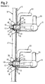
- the muffle front side mounting of the guide elements 11 in the bearing bushes 15 is in of Figure 2 shown in detail. Accordingly, in the figure 3 as a single part shown bearing bush 15 hollow cylindrical with an outer edge flange 23rd educated. This is supported inside a cooking chamber of the muffle 1 inside on the Muffle side wall 9 from.
- the muffle side wall 9 consists of a thin steel sheet with a wall thickness in the range 0.3 to 0.7 mm.
- the edge flange 23 of the bearing bush 15 is garraumayne character in one Insertion cylinder 25 via.
- the insertion cylinder 25 serves as an insertion aid for a Bearing pin 27, which at a rod end of the rod-shaped guide member 11th is trained.
- a hexagon socket provided to with an appropriate tool the Bearing bush 15 to be able to mount in an opening 10 of the muffle side wall 9.
- a the cooking chamber 25 facing insertion opening of the bearing bush 15 is of a Front flange 31 moved frontally.
- the front flange 31 of the bearing bush 15 is from Edge flange 23 axially spaced. In between, an annular groove 33 is formed. These serves as described later, as a holding portion for suspending the Telescopic extensions 59.
- the bearing bush 15 is provided on the outer circumference with an external thread 35, via that the bearing bush according to the figure 2 is screwed into the muffle side wall 9.
- corresponding mating thread 39 is not in the thin-walled Muffle side wall 9 self-formed. Rather, the mating thread 39 in one Secured element 37 is formed.
- the securing element 37 is shown in FIG. 2 on the outside with the muffle side wall 9 in Appendix. It is used as an elongated profile part formed the corresponding mating threads 39 for the bushings 15.
- the Profile member 17 is a cross-sectionally U-shaped steel sheet, which also at thermal load remains torsionally rigid and dimensionally stable.
- Each of the mating threads 39 is incorporated in the manner of a metal nut in the profile part 37.
- the profile part 37 extends in a vertical direction over all bushings shown in Figure 1 15 of a muffle side wall 9. Due to the large-scale investment of the profile part 37 at the Outside the side wall 9, the bushings 15 are stable against tilting moments fastened, despite the thin-walled muffle side wall 9. Approximately midway between the two legs of the U-shaped security element 37 are the Counter thread 39 formed.
- the bushing 15 is with its external thread 35 with a game through the opening 10th the muffle side wall 9 out.
- the bushing 15 is therefore not directly with the Muffle side wall 9 bolted. Rather, the muffle side wall 9 between the Secured securing element 37 and the edge flange 23 of the bearing bush 15.
- the bearing pin 27 of the guide member 11 on reduces a diameter of a positive storage in the bearing bush 15th allowed. As a result, a play-free mounting of the guide member 11 in the Bushing 15 reached. This is further supported by a contact shoulder 51 of the Bearing pin 27 which is in contact with the front flange 31 of the bearing bush 15.
- the bearing bush 15 is shown in a modification. In contrast to the bearing bush shown in Figure 3 is in the bearing bush of Figure 4 on the Front flange 31 omitted.
- the bushing 15 therefore has garrauminnen picture only the edge flange 23.
- the abutment shoulder 51 in corresponding manner pressed against the edge flange 23 of the bearing pin 27.
- FIG. 5 shows a guide element 11 removed from the cooking appliance muffle 1 shown.
- the bearing pin 27 is connected to a rod end of the guide member 11 with formed a reduced diameter. Since the guide element 11 of a Solid material consists, manufacturing technology easy, such as by means of a lathe the bearing bolts 27 are formed on the rod end. The with the bearing pin 27th provided rod end of the guide member 11 is also bent angularly. A For this necessary Biegeformung is compared to a hollow material in the here used solid material manufacturing technology easily feasible.
- the guide elements 11 and telescopic extensions 59 are each independent of each other formed and inserted into the muffle 1, as can be seen from the figure 1. Consequently, they can also be taken independently of each other from the oven unless they are needed to hold a food support. Thereby can thermally advantageous material entry into the cooking appliance muffle 1 possible be kept low.
- the L-shaped guide member 11 is provided with a along the Muffel side wall 9 elongated legs formed, the leadership and Support of insertion parts is used.
- the L-shape of the guide member 11 allows it, the guide member 11 with its muffle back rod end 54 at the Muffle back wall 17 and with the bent muffle front side bar end at the Muffle side wall 9 to hold. Through this bracket on two different Muffle walls, the guide member 11 is more resistant to tilting moments.
- Muffle front side is on the guide member 11, a height stop 53 as a tilt protection for Insertion parts provided.
- This one is as a curved steel wire hanger with its two Ends pressed into corresponding holes of the guide member 11.
- Corresponding is in the region of the muffle back rod end 54 offset by 90 ° another hole formed in the guide element 11.
- a steel pin is pressed in as a Slide-in stop 55 is used for an insertion part.
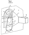
- FIG. 6 shows an alternative use of the bearing bush 15.
- a retaining plate 57 of the one shown in the figure 1 is alternatively Telescopic extension 59 mounted in the annular groove 33 of the bearing bush 15.
- the pin 61 is like the rear rod end 54 of the Guiding elements 11 formed.
- the muffle front side holding plate 57 is as a steel sheet with a punched slot 63 trained.
- the slot 63 extends perpendicular to the elongated Telescopic extension 59 and serves to hook the retaining plate 57 in the annular groove 33 of Bearing bush 15.
- the slot 63 as an inverted keyhole with a widened insertion portion 65 and a narrow securing portion 67 in FIG the holding plate 57 punched.
- the diameter of the expanded insertion portion 65 is larger than the diameter of the front flange 31 of the bushing 15. Accordingly can the support plate 57 is simply guided over the front flange 31 of the bearing bush 15 and be hung in the annular groove 33.
- the wall thickness of the holding plate 57 is smaller as a groove width of the annular groove 33 of the bearing bush 15.
- the opposite lateral Limiting edges of the securing portion 67 are in the figure 6 within the Ring groove 33 of the bearing bush 15 is arranged. This is an axial movement of the hinged holding plate 57 along the bearing bush 15 prevented.
- a leaf spring 69 by means of a rivet 71 with the Rivet plate 57 riveted.
- the leaf spring 69 acts like a locking element.
- the leaf spring 69 shown in its locking position. In this position is an upper one Locking edge 73 of the leaf spring 69 in abutment with a circumference of the front flange 31 of the bushing 15 or slightly spaced therefrom. An accidental Movement of the holding plate 57 upwards is thus prevented by the leaf spring 69. Accordingly, therefore, an accidental release of the holding plate 57 of the Bearing bush 15 prevented.
- the leaf spring 69 has according to the figure 6 an actuating portion 75. This one can be pressed in the direction of the arrow shown, whereby the locking edge 73rd is pivoted in the direction of the arrow shown in the cooking chamber. In this position is the locking edge 73 of the leaf spring 69 out of engagement with the bearing bush 15. Die Holding plate 57 of the telescopic extension 59 can therefore for a removal of the Telescopic extension 59 are raised, so that the bearing bush 15 from the Insertion section 65 of the holding plate 57 can be led out.
- the leaf spring 69 When removed telescopic extension 59, the leaf spring 69 is with her Locking edge 73 directly on the holding plate 57 and overlaps the insertion section 65th of the slot 63.
- the Bearing bush 15 For a renewed hanging of the telescopic extension 59 is the Bearing bush 15 through the slot insertion section 65 of the support plate 57 to lead. On In this way, the bearing bush 15 presses the leaf spring 69 with its locking edge 73rd away from the holding plate 57.
- the telescopic extension 59 can be slightly lowered by the user, until the bushing 15 in the narrow securing portion 67 of the slot 63rd is as shown in Figure 6.
- the leaf spring 69 automatically jumped back into its locking position.
- the leaf spring 69 can only be tilted from the locking position to an unlocking position when a User presses on their operating section 75.
- the Holding plate 57 of the telescopic extension 59 are slightly raised by the user.
- the bearing bush 15 is arranged in the insertion section 65 of the elongated hole 63.
- the holding plate 59 by an axial movement of the bearing bush 15 are solved.
- FIG. 7 and 8 are concerned with the storage of the rod-shaped guide member 11 and the journal 61 of the telescopic extension 59 on the rear side wall of the Cooking appliance muffle 1.
- each side one Wall element 21 arranged with corresponding mounting holes 19.
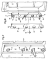
- the wall element 21 is shown in FIG. 8 as a angled U-profile part made of a steel sheet with a large heat-resistant Stiffness trained.
- the U-profile part 21 has a leg at its one at right angles bent abutment flange 77. This is about locking screws 79th large area in plant with a mounting surface of a muffle back wall side Air guide plate 81 mounted.
- the air guide plate 81 separates a not shown Ring radiator and a fan from the oven. Through this assembly at the Air guide plate 81 is achieved that no additional openings for attachment of the U-profile part 81, for the storage of the telescopic extension 59 or for storage of the Guide element 11 must be formed in the muffle back wall 17.
- the back Side wall of Garellamuffel 1 consists according to the figures 7 and 8 of the Muffle back wall 17, the air guide plate 81 and the garrauminnen remedyen Wall elements 21.
- the angled U-profile part 21 also has a mounting flange 83. This is offset relative to the abutment flange 77 in the direction of the cooking chamber.
- Mounting flange 83 are in a vertical row, the mounting holes 19 for the Guide elements 11 and formed for the bearing pin 61 of the telescopic extension 59.
- each of the assembly openings 19 moves a cup-like edge embossing or a collar 85 which projects into the cooking chamber.
- This Collar 85 serves as a butt edge during the insertion of the journal 61 and the Stabendes 54.
- an additional diaphragm 87 is provided on the wall element 21 set to shield the U-profile part 21 relative to the cooking chamber.
- the aperture 87 designed as a U-shaped sheet steel profile part, the corresponding to the mounting holes 19 of the U-profile part 21 apertures 89th having. Their diameter is made slightly larger than the diameter of the Collar 85 of the mounting opening 19.
- the cup-shaped collar 85 protrudes in the mounted Condition according to the figure 7 through the aperture 89 in the oven.
- the collar 85 can function as an insertion aid for the Bearing 61 and the rod end 54 meet.
- the cooking chamber facing surface of the aperture 87 is corresponding to the Muffle walls surface-treated, d. H. in the present case with an enamel layer Mistake.
- the aperture 87 occurs optically together with the wall element 23 largely in the background.
- the aperture 87 is not directly in contact with the air guide plate 81. Rather, the aperture is small, d. H. at least non-contact of the Air guide plate 81 spaced. Corresponding damage to the enamel layer the air guide plate 81 through the aperture 87 can be avoided.
Landscapes
- Engineering & Computer Science (AREA)
- Chemical & Material Sciences (AREA)
- Combustion & Propulsion (AREA)
- Mechanical Engineering (AREA)
- General Engineering & Computer Science (AREA)
- Baking, Grill, Roasting (AREA)
- Food-Manufacturing Devices (AREA)
- Cookers (AREA)
- Mounting Of Bearings Or Others (AREA)
Abstract
Description
- Figur 1
- in einer perspektivischen Ansicht ein Gargerät mit frontseitig offener Gargerätetür;
- Figur 2
- in einer vergrößerten Schnittansicht die Einzelheit I aus der Figur 1;
- Figur 3
- in einer perspektivischen Schnittansicht eine Lagerbuchse für ein Führungselement;
- Figur 4
- in einer Seitenschnittdarstellung eine Abwandlung der Lagerbuchse;
- Figur 5
- in einer perspektivischen Ansicht das Führungselement;
- Figur 6
- in einer vergrößerten Darstellung die Einzelheit II aus der Figur 1;
- Figur 7
- in einer vergrößerten Darstellung ein Wandelement zur muffelrückwandseitigen Halterung der Führungselemente; und
- Figur 8
- in einer perspektivischen Explosionsdarstellung das Wandelement mit einer muffelrückwandseitigen Luftführungsplatte.
Claims (31)
- Haushaltsgerät, insbesondere Gargerät mit einer Gerätemuffel (1), in dessen Muffelwand (9) zumindest ein Zubehörteil (11) gehaltert ist, das einen Lagerbolzen (27) aufweist, der lösbar durch eine Montageöffnung (10) in der Muffelwand (9) geführt ist, dadurch gekennzeichnet, dass in der Montageöffnung (10) der Muffelwand (9) eine Lagerbuchse (15) eingesetzt ist, in der der Lagerbolzen (27) des Zubehörteiles (11, 59) gelagert ist.
- Haushaltsgerät nach Anspruch 1, dadurch gekennzeichnet, dass die Lagerbuchse (15) mit einem garrauminnenseitig angeordneten Randflansch (23) ausgebildet ist, der die Lagerbuchse (15) radial umzieht.
- Haushaltsgerät nach Anspruch 2, dadurch gekennzeichnet, dass der Randflansch (23) der Lagerbuchse (15) sich garrauminnenseitig auf der Muffelwand (9) abstützt.
- Haushaltsgerät nach einem der vorhergehenden Ansprüche, dadurch gekennzeichnet, dass die Lagerbuchse (15) mit einem in den Garraum ragenden Einführzylinder (25) zum Einführen des Lagerbolzens (27) ausgebildet ist.
- Haushaltsgerät nach einem der vorhergehenden Ansprüche, dadurch gekennzeichnet, dass die Lagerbuchse (15) mit einem Frontflansch (31) ausgebildet ist, der eine Einführöffnung der Lagerbuchse (15) stirnseitig umzieht.
- Haushaltsgerät nach einem der vorhergehenden Ansprüche, dadurch gekennzeichnet, dass die Lagerbuchse (15) mit einem Halterungsabschnitt (33) zum Einhängen eines Einhängeteiles (59) ausgebildet ist.
- Haushaltsgerät nach Anspruch 6, dadurch gekennzeichnet, dass der Halterungsabschnitt (33) der Lagerbuchse (15) als eine zumindest teilweise die Lagerbuchse (15) umziehende Ringnut (33) ausgebildet ist.
- Haushaltsgerät nach einem der Ansprüche 6 oder 7, dadurch gekennzeichnet, dass der Halterungsabschnitt (33) und der Randflansch (23) in einer Axialrichtung hintereinander auf der Lagerbuchse (15) ausgebildet sind.
- Haushaltsgerät nach einem der Ansprüche 2 bis 8, dadurch gekennzeichnet, dass der Lagerbolzen (27) mit einer Anlageschulter (51) ausgebildet ist, die mit dem Frontflansch (31) oder dem Randflansch (23) der Lagerbuchse (15) in Anlage ist.
- Haushaltsgerät nach einem der vorhergehenden Ansprüche, dadurch gekennzeichnet, dass die Lagerbuchse (15) innenseitig einen Werkzeugansatz (29) aufweist.
- Haushaltsgerät nach einem der vorhergehenden Ansprüche, dadurch gekennzeichnet, dass die Lagerbuchse (15) rückseitig geschlossen ist.
- Haushaltsgerät nach einem der vorhergehenden Ansprüche, dadurch gekennzeichnet, dass der Lagerbuchse (15) an einem Sicherungselement (37) gehaltert ist, das außenseitig an der Muffelwand (9) angeordnet ist.
- Haushaltsgerät nach Anspruch 12, dadurch gekennzeichnet, dass das Sicherungselement (37) eine Sicherungsmutter ist, die mit einem Außengewinde (35) der Lagerbuchse (15) verschraubt ist.
- Haushaltsgerät nach einem der Ansprüche 12, dadurch gekennzeichnet, dass das Sicherungselement (37) ein Profilteil ist, das außenseitig mit der Muffelwand (9) in Anlage ist.
- Haushaltsgerät nach Anspruch 14, dadurch gekennzeichnet, dass das Profilteil (37) zumindest einen oder mehrere Schraubgewindeabschnitte (39) zum Verschrauben mit Lagerbuchsen (15) aufweist.
- Haushaltsgerät nach einem der vorhergehenden Ansprüche, dadurch gekennzeichnet, dass der Lagerbuchse (15) zumindest ein Rastelement und/oder Riegelelement (45, 69) zugeordnet ist, die ein Lösen des Zubehörteils (11) und/oder des Einhängeteils (59) verhindern.
- Haushaltsgerät nach Anspruch 16, dadurch gekennzeichnet, dass das Rastelement (45) als eine Feder ausgebildet ist, die mit zumindest einem Federschenkel in den Lagerbolzen (27) rastet.
- Haushaltsgerät nach Anspruch 17, dadurch gekennzeichnet, dass das Rastelement (45) an der Lagerbuchse (15) gehaltert ist.
- Haushaltsgerät nach Anspruch 16 oder 17, dadurch gekennzeichnet, dass das Rastelement (45) an dem Sicherungselement (37) gehaltert ist.
- Haushaltsgerät nach einem der vorhergehenden Ansprüche, dadurch gekennzeichnet, dass der Lagerbolzen (27) des Zubehörteiles (11) stirnseitig mit einem Einführkonus (49) ausgebildet ist.
- Haushaltsgerät nach einem der Ansprüche 16 bis 20, dadurch gekennzeichnet, dass der Lagerbolzen (27) hinter dem Einführkonus (49) eine Rastnut (47) aufweist, in die das Rastelement (45) einrastet.
- Haushaltsgerät nach Anspruch 21, dadurch gekennzeichnet, dass zwischen dem Einführkonus (49) und der Rastnut (47) ein Zylinderabschnitt ausgebildet ist, dessen Durchmesser eine Kraft zum Einrasten des Lagerbolzens (27) festlegt.
- Haushaltsgerät nach einem der Ansprüche 6 bis 22, dadurch gekennzeichnet, dass das Einhängeteil (59) eine Halteplatte (57) zum Einhängen in den Halterungsabschnitt (33) der Lagerbuchse (15) aufweist.
- Haushaltsgerät nach Anspruch 23, dadurch gekennzeichnet, dass eine Wandstärke der Halteplatte (57) geringer ist als eine Nutbreite der Ringnut (33) der Lagerbuchse (15).
- Haushaltsgerät nach Anspruch 6 bis 24, dadurch gekennzeichnet, dass das Einhängeteil (59) mit einer Aussparung (63) zum Einhängen in die Lagerbuchse (15) ausgebildet ist.
- Haushaltsgerät nach Anspruch 25, dadurch gekennzeichnet, dass die Aussparung (63) als ein Langloch in der Halteplatte (57) ausgebildet ist.
- Haushaltsgerät nach Anspruch 26, dadurch gekennzeichnet, dass das Langloch (63) der Halteplatte (57) einen ausgeweiteten Einführabschnitt (65) zum Durchführen der Lagerbuchse (15) aufweist.
- Haushaltsgerät nach Anspruch 26 oder 27, dadurch gekennzeichnet, dass das Langloch (63) einen Sicherungsabschnitt (67) aufweist, und die Halteplatte (57) bei einer Anordnung der Lagerbuchse (15) im Sicherungsabschnitt (67) gegen ein axiales Lösen von der Lagerbuchse (15) gesichert ist.
- Haushaltsgerät nach einem der Ansprüche 16 bis 28, dadurch gekennzeichnet, dass das Riegelelement (69) in einer Verriegelungsposition ein Lösen des Einhängeteils (59) von der Lagerbuchse (15) verhindert.
- Haushaltsgerät nach Anspruch 29, dadurch gekennzeichnet, dass das Riegelelement (69) als ein Federelement ausgebildet ist.
- Haushaltsgerät nach Anspruch 29 oder 30, dadurch gekennzeichnet, dass in einer Entriegelungsposition des Riegelelements (69) ein Lösen des Einhängeteils (59) von der Lagerbuchse (15) ermöglicht ist.
Applications Claiming Priority (2)
| Application Number | Priority Date | Filing Date | Title |
|---|---|---|---|
| DE102004001685A DE102004001685A1 (de) | 2004-01-12 | 2004-01-12 | Haushaltsgerät, insbesondere Gargerät |
| DE102004001685 | 2004-01-12 |
Publications (3)
| Publication Number | Publication Date |
|---|---|
| EP1553349A2 true EP1553349A2 (de) | 2005-07-13 |
| EP1553349A3 EP1553349A3 (de) | 2005-07-20 |
| EP1553349B1 EP1553349B1 (de) | 2009-11-11 |
Family
ID=34585399
Family Applications (1)
| Application Number | Title | Priority Date | Filing Date |
|---|---|---|---|
| EP05100105A Expired - Lifetime EP1553349B1 (de) | 2004-01-12 | 2005-01-11 | Haushaltsgerät, insbesondere Gargerät mit Haltevorrichtung |
Country Status (3)
| Country | Link |
|---|---|
| EP (1) | EP1553349B1 (de) |
| AT (1) | ATE448450T1 (de) |
| DE (2) | DE102004001685A1 (de) |
Cited By (4)
| Publication number | Priority date | Publication date | Assignee | Title |
|---|---|---|---|---|
| WO2014048732A1 (de) * | 2012-09-26 | 2014-04-03 | BSH Bosch und Siemens Hausgeräte GmbH | Lagerbuchse, welche zum lagern eines haushaltsgerätebauteils an einer haushaltsgerätekomponente ausgebildet ist, sowie haushaltsgerät mit einer derartigen lagerbuchse |
| ES2526621A1 (es) * | 2013-07-09 | 2015-01-13 | Bsh Electrodomésticos España, S.A. | Sistema de fijación para un alojamiento para soporte de producto de cocción |
| WO2019129402A1 (en) | 2017-12-25 | 2019-07-04 | Arcelik Anonim Sirketi | An oven comprising shelf support made of wire |
| EP3800401A1 (de) * | 2019-10-01 | 2021-04-07 | Arçelik Anonim Sirketi | Kochvorrichtung |
Families Citing this family (4)
| Publication number | Priority date | Publication date | Assignee | Title |
|---|---|---|---|---|
| DE102012200316A1 (de) * | 2012-01-11 | 2013-07-11 | BSH Bosch und Siemens Hausgeräte GmbH | Lagerbuchse, welche zum Lagern eines Haushaltsgerätebauteils an einer Haushaltsgerätekomponente ausgebildet ist, sowie Haushaltsgerät mit einer derartigen Lagerbuchse |
| SI24148A (sl) * | 2012-07-12 | 2014-01-31 | Gorenje Gospodinjski Aparati D.D. | Pritrditev rešetkastega nosilca vodil v pečici |
| DE102012215263A1 (de) * | 2012-08-28 | 2014-03-06 | BSH Bosch und Siemens Hausgeräte GmbH | Gargerät |
| DE102014109729B3 (de) * | 2014-07-11 | 2015-08-20 | Miele & Cie. Kg | Gargerät und Befestigungssystem |
Citations (4)
| Publication number | Priority date | Publication date | Assignee | Title |
|---|---|---|---|---|
| US2944139A (en) | 1959-01-27 | 1960-07-05 | Philco Corp | Cooking range oven with removable liner |
| DE1579669A1 (de) | 1965-06-07 | 1970-09-10 | Gen Electric | Waermebehandlungseinrichtung,insbesondere Haushaltswaermebehandlungseinrichtung |
| DE2522566A1 (de) | 1975-05-22 | 1976-12-09 | Robert Gary Wilson | Ausstellungsgrill |
| DE10240627A1 (de) | 2002-09-03 | 2004-03-11 | BSH Bosch und Siemens Hausgeräte GmbH | Trägervorrichtung, insbesondere für ein Gargerät |
Family Cites Families (9)
| Publication number | Priority date | Publication date | Assignee | Title |
|---|---|---|---|---|
| CH357849A (de) * | 1958-02-28 | 1961-10-31 | Schweiz Gasapparate Fabrik Sol | Grilliervorrichtung |
| DE1980911U (de) * | 1967-07-06 | 1968-03-14 | Siemens Elektrogeraete Gmbh | Back- und bratrohr. |
| CH585518A5 (de) * | 1975-06-12 | 1977-03-15 | Elektromaschinen Ag | |
| DE2705063A1 (de) * | 1977-02-08 | 1978-08-10 | Witte & Co Stephan | Mikrowellenherd |
| US4195888A (en) * | 1978-07-13 | 1980-04-01 | Magic Chef, Inc. | Mounting socket |
| JPS5816127A (ja) * | 1981-07-21 | 1983-01-29 | Matsushita Electric Ind Co Ltd | 高周波加熱装置 |
| US5338922A (en) * | 1992-02-17 | 1994-08-16 | Samsung Electronics Co., Ltd. | Tray extending apparatuses for an oven |
| DE10162925A1 (de) * | 2001-12-20 | 2003-07-03 | Bsh Bosch Siemens Hausgeraete | Auszugssystem eines Haushaltsgeräts, insbesondere eines Gargeräts |
| DE20314180U1 (de) * | 2003-09-12 | 2003-11-06 | Lötters Metallwaren GmbH, 58638 Iserlohn | Backofenauszug |
-
2004
- 2004-01-12 DE DE102004001685A patent/DE102004001685A1/de not_active Withdrawn
-
2005
- 2005-01-11 AT AT05100105T patent/ATE448450T1/de not_active IP Right Cessation
- 2005-01-11 EP EP05100105A patent/EP1553349B1/de not_active Expired - Lifetime
- 2005-01-11 DE DE502005008462T patent/DE502005008462D1/de not_active Expired - Lifetime
Patent Citations (4)
| Publication number | Priority date | Publication date | Assignee | Title |
|---|---|---|---|---|
| US2944139A (en) | 1959-01-27 | 1960-07-05 | Philco Corp | Cooking range oven with removable liner |
| DE1579669A1 (de) | 1965-06-07 | 1970-09-10 | Gen Electric | Waermebehandlungseinrichtung,insbesondere Haushaltswaermebehandlungseinrichtung |
| DE2522566A1 (de) | 1975-05-22 | 1976-12-09 | Robert Gary Wilson | Ausstellungsgrill |
| DE10240627A1 (de) | 2002-09-03 | 2004-03-11 | BSH Bosch und Siemens Hausgeräte GmbH | Trägervorrichtung, insbesondere für ein Gargerät |
Cited By (4)
| Publication number | Priority date | Publication date | Assignee | Title |
|---|---|---|---|---|
| WO2014048732A1 (de) * | 2012-09-26 | 2014-04-03 | BSH Bosch und Siemens Hausgeräte GmbH | Lagerbuchse, welche zum lagern eines haushaltsgerätebauteils an einer haushaltsgerätekomponente ausgebildet ist, sowie haushaltsgerät mit einer derartigen lagerbuchse |
| ES2526621A1 (es) * | 2013-07-09 | 2015-01-13 | Bsh Electrodomésticos España, S.A. | Sistema de fijación para un alojamiento para soporte de producto de cocción |
| WO2019129402A1 (en) | 2017-12-25 | 2019-07-04 | Arcelik Anonim Sirketi | An oven comprising shelf support made of wire |
| EP3800401A1 (de) * | 2019-10-01 | 2021-04-07 | Arçelik Anonim Sirketi | Kochvorrichtung |
Also Published As
| Publication number | Publication date |
|---|---|
| EP1553349A3 (de) | 2005-07-20 |
| DE502005008462D1 (de) | 2009-12-24 |
| ATE448450T1 (de) | 2009-11-15 |
| DE102004001685A1 (de) | 2005-08-04 |
| EP1553349B1 (de) | 2009-11-11 |
Similar Documents
| Publication | Publication Date | Title |
|---|---|---|
| EP1840473A2 (de) | Teleskopauszugsvorrichtung zur Befestigung an einem in dem Behandlungsraum eines Haushaltsgeräts angeordneten Traggestell | |
| EP0813038A2 (de) | Haltevorrichtung für ein Gewehr und Bausatz zum Zusammenbau einer derartigen Haltevorrichtung | |
| EP2703731B1 (de) | Lagerbuchse für ein Haushaltsgerät mit einem pilzförmigen Basiskörper mit einem frontseitig zugänglichen Hohlraum sowie Haushaltsgerät | |
| EP3111801B1 (de) | Aufhängevorrichtung für ein möbel | |
| EP3681347B1 (de) | Blendenträger und schubkasten | |
| EP1553349A2 (de) | Haushaltsgerät, insbesondere Gargerät mit Haltevorrichtung | |
| EP1506342A2 (de) | Türlagerwinkel für ein schrankartiges haushaltsgerät | |
| EP1553352B1 (de) | Haushaltsgerät, insbesondere Gargerät sowie Herstellungsverfahren | |
| EP1553351B1 (de) | Haushaltsgerät, insbesondere Gargerät | |
| EP1553350B1 (de) | Gargerät | |
| DE102009052026B4 (de) | Einbaurahmen mit Befestigungsvorrichtung | |
| EP3592993B1 (de) | Spannverbinder und befestigungsanordnung mit einem solchen | |
| DE102015211076B3 (de) | Befestigungsvorrichtung für Dunstabzugshaube, Dunstabzugshaube mit Befestigungsvorrichtung und Aufhängesystem | |
| EP1553347B1 (de) | Haushaltsgerät, insbesondere Gargerät | |
| DE102006062070B4 (de) | Gargerätevorrichtung und Gargerät | |
| EP1505705B1 (de) | Montagevorrichtung für Kabelkanäle | |
| DE102013018119B3 (de) | Behältnis | |
| DE102017122674B4 (de) | Leuchtmittelhalterung und Objekt mit einer Leuchtmittelhalterung | |
| DE102010022214B4 (de) | Wandstruktur für ein Gargerät | |
| WO2002032259A1 (de) | Tragsäule eines eckschrankkarussells | |
| EP3271537B1 (de) | Vorrichtung zur halterung von gegenständen | |
| DE102023135876A1 (de) | Teleskopauszug mit Aushebesicherung | |
| DE19745090A1 (de) | Hausgerät, insbesondere Kühl und/oder Gefriergerät, für den Einbau in einen Möbelumbau | |
| DE102021203579A1 (de) | Halterung und Halterungssystem zum Befestigen eines Haushaltsgeräts | |
| DE102015119991A1 (de) | Haltevorrichtung für einen Regalboden an einer Regalwand und Regal mit einer solchen Haltevorrichtung |
Legal Events
| Date | Code | Title | Description |
|---|---|---|---|
| PUAI | Public reference made under article 153(3) epc to a published international application that has entered the european phase |
Free format text: ORIGINAL CODE: 0009012 |
|
| PUAL | Search report despatched |
Free format text: ORIGINAL CODE: 0009013 |
|
| AK | Designated contracting states |
Kind code of ref document: A2 Designated state(s): AT BE BG CH CY CZ DE DK EE ES FI FR GB GR HU IE IS IT LI LT LU MC NL PL PT RO SE SI SK TR |
|
| AX | Request for extension of the european patent |
Extension state: AL BA HR LV MK YU |
|
| AK | Designated contracting states |
Kind code of ref document: A3 Designated state(s): AT BE BG CH CY CZ DE DK EE ES FI FR GB GR HU IE IS IT LI LT LU MC NL PL PT RO SE SI SK TR |
|
| AX | Request for extension of the european patent |
Extension state: AL BA HR LV MK YU |
|
| 17P | Request for examination filed |
Effective date: 20060120 |
|
| AKX | Designation fees paid |
Designated state(s): AT BE BG CH CY CZ DE DK EE ES FI FR GB GR HU IE IS IT LI LT LU MC NL PL PT RO SE SI SK TR |
|
| 17Q | First examination report despatched |
Effective date: 20080509 |
|
| GRAP | Despatch of communication of intention to grant a patent |
Free format text: ORIGINAL CODE: EPIDOSNIGR1 |
|
| GRAS | Grant fee paid |
Free format text: ORIGINAL CODE: EPIDOSNIGR3 |
|
| GRAA | (expected) grant |
Free format text: ORIGINAL CODE: 0009210 |
|
| AK | Designated contracting states |
Kind code of ref document: B1 Designated state(s): AT BE BG CH CY CZ DE DK EE ES FI FR GB GR HU IE IS IT LI LT LU MC NL PL PT RO SE SI SK TR |
|
| REG | Reference to a national code |
Ref country code: GB Ref legal event code: FG4D Free format text: NOT ENGLISH |
|
| REG | Reference to a national code |
Ref country code: CH Ref legal event code: EP |
|
| REG | Reference to a national code |
Ref country code: IE Ref legal event code: FG4D |
|
| REF | Corresponds to: |
Ref document number: 502005008462 Country of ref document: DE Date of ref document: 20091224 Kind code of ref document: P |
|
| NLV1 | Nl: lapsed or annulled due to failure to fulfill the requirements of art. 29p and 29m of the patents act | ||
| LTIE | Lt: invalidation of european patent or patent extension |
Effective date: 20091111 |
|
| PG25 | Lapsed in a contracting state [announced via postgrant information from national office to epo] |
Ref country code: PT Free format text: LAPSE BECAUSE OF FAILURE TO SUBMIT A TRANSLATION OF THE DESCRIPTION OR TO PAY THE FEE WITHIN THE PRESCRIBED TIME-LIMIT Effective date: 20100311 Ref country code: LT Free format text: LAPSE BECAUSE OF FAILURE TO SUBMIT A TRANSLATION OF THE DESCRIPTION OR TO PAY THE FEE WITHIN THE PRESCRIBED TIME-LIMIT Effective date: 20091111 Ref country code: SE Free format text: LAPSE BECAUSE OF FAILURE TO SUBMIT A TRANSLATION OF THE DESCRIPTION OR TO PAY THE FEE WITHIN THE PRESCRIBED TIME-LIMIT Effective date: 20091111 Ref country code: FI Free format text: LAPSE BECAUSE OF FAILURE TO SUBMIT A TRANSLATION OF THE DESCRIPTION OR TO PAY THE FEE WITHIN THE PRESCRIBED TIME-LIMIT Effective date: 20091111 Ref country code: ES Free format text: LAPSE BECAUSE OF FAILURE TO SUBMIT A TRANSLATION OF THE DESCRIPTION OR TO PAY THE FEE WITHIN THE PRESCRIBED TIME-LIMIT Effective date: 20100222 Ref country code: IS Free format text: LAPSE BECAUSE OF FAILURE TO SUBMIT A TRANSLATION OF THE DESCRIPTION OR TO PAY THE FEE WITHIN THE PRESCRIBED TIME-LIMIT Effective date: 20100311 |
|
| PG25 | Lapsed in a contracting state [announced via postgrant information from national office to epo] |
Ref country code: PL Free format text: LAPSE BECAUSE OF FAILURE TO SUBMIT A TRANSLATION OF THE DESCRIPTION OR TO PAY THE FEE WITHIN THE PRESCRIBED TIME-LIMIT Effective date: 20091111 Ref country code: SI Free format text: LAPSE BECAUSE OF FAILURE TO SUBMIT A TRANSLATION OF THE DESCRIPTION OR TO PAY THE FEE WITHIN THE PRESCRIBED TIME-LIMIT Effective date: 20091111 Ref country code: CY Free format text: LAPSE BECAUSE OF FAILURE TO SUBMIT A TRANSLATION OF THE DESCRIPTION OR TO PAY THE FEE WITHIN THE PRESCRIBED TIME-LIMIT Effective date: 20091111 |
|
| REG | Reference to a national code |
Ref country code: IE Ref legal event code: FD4D |
|
| PG25 | Lapsed in a contracting state [announced via postgrant information from national office to epo] |
Ref country code: EE Free format text: LAPSE BECAUSE OF FAILURE TO SUBMIT A TRANSLATION OF THE DESCRIPTION OR TO PAY THE FEE WITHIN THE PRESCRIBED TIME-LIMIT Effective date: 20091111 Ref country code: BG Free format text: LAPSE BECAUSE OF FAILURE TO SUBMIT A TRANSLATION OF THE DESCRIPTION OR TO PAY THE FEE WITHIN THE PRESCRIBED TIME-LIMIT Effective date: 20100211 Ref country code: IE Free format text: LAPSE BECAUSE OF FAILURE TO SUBMIT A TRANSLATION OF THE DESCRIPTION OR TO PAY THE FEE WITHIN THE PRESCRIBED TIME-LIMIT Effective date: 20091111 Ref country code: DK Free format text: LAPSE BECAUSE OF FAILURE TO SUBMIT A TRANSLATION OF THE DESCRIPTION OR TO PAY THE FEE WITHIN THE PRESCRIBED TIME-LIMIT Effective date: 20091111 Ref country code: RO Free format text: LAPSE BECAUSE OF FAILURE TO SUBMIT A TRANSLATION OF THE DESCRIPTION OR TO PAY THE FEE WITHIN THE PRESCRIBED TIME-LIMIT Effective date: 20091111 |
|
| BERE | Be: lapsed |
Owner name: BSH BOSCH UND SIEMENS HAUSGERATE G.M.B.H. Effective date: 20100131 |
|
| PG25 | Lapsed in a contracting state [announced via postgrant information from national office to epo] |
Ref country code: CZ Free format text: LAPSE BECAUSE OF FAILURE TO SUBMIT A TRANSLATION OF THE DESCRIPTION OR TO PAY THE FEE WITHIN THE PRESCRIBED TIME-LIMIT Effective date: 20091111 Ref country code: MC Free format text: LAPSE BECAUSE OF NON-PAYMENT OF DUE FEES Effective date: 20100131 Ref country code: SK Free format text: LAPSE BECAUSE OF FAILURE TO SUBMIT A TRANSLATION OF THE DESCRIPTION OR TO PAY THE FEE WITHIN THE PRESCRIBED TIME-LIMIT Effective date: 20091111 |
|
| REG | Reference to a national code |
Ref country code: CH Ref legal event code: PL |
|
| PLBE | No opposition filed within time limit |
Free format text: ORIGINAL CODE: 0009261 |
|
| STAA | Information on the status of an ep patent application or granted ep patent |
Free format text: STATUS: NO OPPOSITION FILED WITHIN TIME LIMIT |
|
| 26N | No opposition filed |
Effective date: 20100812 |
|
| REG | Reference to a national code |
Ref country code: FR Ref legal event code: ST Effective date: 20100930 |
|
| PG25 | Lapsed in a contracting state [announced via postgrant information from national office to epo] |
Ref country code: LI Free format text: LAPSE BECAUSE OF NON-PAYMENT OF DUE FEES Effective date: 20100131 Ref country code: GR Free format text: LAPSE BECAUSE OF FAILURE TO SUBMIT A TRANSLATION OF THE DESCRIPTION OR TO PAY THE FEE WITHIN THE PRESCRIBED TIME-LIMIT Effective date: 20100212 Ref country code: FR Free format text: LAPSE BECAUSE OF NON-PAYMENT OF DUE FEES Effective date: 20100201 Ref country code: CH Free format text: LAPSE BECAUSE OF NON-PAYMENT OF DUE FEES Effective date: 20100131 |
|
| PG25 | Lapsed in a contracting state [announced via postgrant information from national office to epo] |
Ref country code: BE Free format text: LAPSE BECAUSE OF NON-PAYMENT OF DUE FEES Effective date: 20100131 |
|
| PG25 | Lapsed in a contracting state [announced via postgrant information from national office to epo] |
Ref country code: IT Free format text: LAPSE BECAUSE OF FAILURE TO SUBMIT A TRANSLATION OF THE DESCRIPTION OR TO PAY THE FEE WITHIN THE PRESCRIBED TIME-LIMIT Effective date: 20091111 |
|
| PG25 | Lapsed in a contracting state [announced via postgrant information from national office to epo] |
Ref country code: AT Free format text: LAPSE BECAUSE OF NON-PAYMENT OF DUE FEES Effective date: 20100111 |
|
| PG25 | Lapsed in a contracting state [announced via postgrant information from national office to epo] |
Ref country code: HU Free format text: LAPSE BECAUSE OF FAILURE TO SUBMIT A TRANSLATION OF THE DESCRIPTION OR TO PAY THE FEE WITHIN THE PRESCRIBED TIME-LIMIT Effective date: 20100512 Ref country code: NL Free format text: LAPSE BECAUSE OF FAILURE TO SUBMIT A TRANSLATION OF THE DESCRIPTION OR TO PAY THE FEE WITHIN THE PRESCRIBED TIME-LIMIT Effective date: 20091111 Ref country code: LU Free format text: LAPSE BECAUSE OF NON-PAYMENT OF DUE FEES Effective date: 20100111 |
|
| PG25 | Lapsed in a contracting state [announced via postgrant information from national office to epo] |
Ref country code: TR Free format text: LAPSE BECAUSE OF FAILURE TO SUBMIT A TRANSLATION OF THE DESCRIPTION OR TO PAY THE FEE WITHIN THE PRESCRIBED TIME-LIMIT Effective date: 20091111 |
|
| REG | Reference to a national code |
Ref country code: DE Ref legal event code: R081 Ref document number: 502005008462 Country of ref document: DE Owner name: BSH HAUSGERAETE GMBH, DE Free format text: FORMER OWNER: BSH BOSCH UND SIEMENS HAUSGERAETE GMBH, 81739 MUENCHEN, DE Effective date: 20150407 |
|
| REG | Reference to a national code |
Ref country code: DE Ref legal event code: R084 Ref document number: 502005008462 Country of ref document: DE |
|
| PGFP | Annual fee paid to national office [announced via postgrant information from national office to epo] |
Ref country code: GB Payment date: 20230124 Year of fee payment: 19 Ref country code: DE Payment date: 20230131 Year of fee payment: 19 |
|
| REG | Reference to a national code |
Ref country code: DE Ref legal event code: R119 Ref document number: 502005008462 Country of ref document: DE |
|
| GBPC | Gb: european patent ceased through non-payment of renewal fee |
Effective date: 20240111 |
|
| PG25 | Lapsed in a contracting state [announced via postgrant information from national office to epo] |
Ref country code: DE Free format text: LAPSE BECAUSE OF NON-PAYMENT OF DUE FEES Effective date: 20240801 |
|
| PG25 | Lapsed in a contracting state [announced via postgrant information from national office to epo] |
Ref country code: GB Free format text: LAPSE BECAUSE OF NON-PAYMENT OF DUE FEES Effective date: 20240111 |
|
| PG25 | Lapsed in a contracting state [announced via postgrant information from national office to epo] |
Ref country code: GB Free format text: LAPSE BECAUSE OF NON-PAYMENT OF DUE FEES Effective date: 20240111 Ref country code: DE Free format text: LAPSE BECAUSE OF NON-PAYMENT OF DUE FEES Effective date: 20240801 |