EP1553378A2 - Bloc collecteur pour batterie d'échange de chaleur à serpentin et ventilateur - Google Patents
Bloc collecteur pour batterie d'échange de chaleur à serpentin et ventilateur Download PDFInfo
- Publication number
- EP1553378A2 EP1553378A2 EP05101575A EP05101575A EP1553378A2 EP 1553378 A2 EP1553378 A2 EP 1553378A2 EP 05101575 A EP05101575 A EP 05101575A EP 05101575 A EP05101575 A EP 05101575A EP 1553378 A2 EP1553378 A2 EP 1553378A2
- Authority
- EP
- European Patent Office
- Prior art keywords
- block according
- branches
- branch
- block
- axis
- Prior art date
- Legal status (The legal status is an assumption and is not a legal conclusion. Google has not performed a legal analysis and makes no representation as to the accuracy of the status listed.)
- Withdrawn
Links
- 239000012530 fluid Substances 0.000 claims abstract description 9
- 238000009826 distribution Methods 0.000 claims abstract description 7
- 238000004891 communication Methods 0.000 claims description 4
- 229910001369 Brass Inorganic materials 0.000 claims description 2
- 239000010951 brass Substances 0.000 claims description 2
- 238000004519 manufacturing process Methods 0.000 abstract description 3
- 238000003754 machining Methods 0.000 description 5
- 238000003466 welding Methods 0.000 description 2
- 238000010276 construction Methods 0.000 description 1
- 238000003780 insertion Methods 0.000 description 1
- 230000037431 insertion Effects 0.000 description 1
- 238000000034 method Methods 0.000 description 1
- 239000002994 raw material Substances 0.000 description 1
Images

Classifications
-
- F—MECHANICAL ENGINEERING; LIGHTING; HEATING; WEAPONS; BLASTING
- F28—HEAT EXCHANGE IN GENERAL
- F28F—DETAILS OF HEAT-EXCHANGE AND HEAT-TRANSFER APPARATUS, OF GENERAL APPLICATION
- F28F27/00—Control arrangements or safety devices specially adapted for heat-exchange or heat-transfer apparatus
- F28F27/02—Control arrangements or safety devices specially adapted for heat-exchange or heat-transfer apparatus for controlling the distribution of heat-exchange media between different channels
-
- F—MECHANICAL ENGINEERING; LIGHTING; HEATING; WEAPONS; BLASTING
- F28—HEAT EXCHANGE IN GENERAL
- F28F—DETAILS OF HEAT-EXCHANGE AND HEAT-TRANSFER APPARATUS, OF GENERAL APPLICATION
- F28F9/00—Casings; Header boxes; Auxiliary supports for elements; Auxiliary members within casings
- F28F9/02—Header boxes; End plates
Definitions
- This invention concerns a block manifold for fitting to heat exchanger batteries and especially for fan coils.
- the heat exchanger batteries have fluid circulation pipes the ends of which are connected to manifolds through which the fluid flow and return pipes are connected.
- manifolds have a block body with a part fitting to fluid piping, two, three or more branches for connection to the battery pipes and a distribution chamber between the fitting and the said branches.
- this cylinder is cylindrical and its geometric axis is oriented transversally to the axes of the fitting and the branches which are substantially parallel to each other.
- this chamber By its presence and conformation, this chamber is already a cause of turbulence in the fluid and a loss of pressure in the system and contributes to pointlessly increasing the external dimensions of the manifold.
- this intermediate cylindrical chamber is left open at one end and is only closed, with a plug, generally welded on, at the end of machining. This plug represents a critical part of the manifold.
- Block manifolds are known in the state of the art, as shown by documents EP-A-0758734, US 4,948,177, US 1,092,385, US 1,160,839, US 1,205,508, US 2,673,101, US 5,176,177, US 3,951,440, US 5,078,432, US 5,143,151, US 5,908,288, GB 10174, GB 897965, US 3,790,966, US 4,013,049, US 4,541,448, US 6,202,686 and US 6,237,408.
- the purpose of this invention is to create and supply a manifold for heat exchanger batteries which is new and original in conformation, capable of providing diverse advantages over manifolds of known technical merit in construction, economical and functional terms.
- a manifold for the use cited above which includes a block body: here, the distribution chamber, located between the fitting and branch parts is coaxial to the fitting and on a parallel axis to the said branches.
- all the parts of the manifold are oriented in parallel to each other in the same direction.
- This allows a reduction in the external dimensions of the body, while maintaining the technical characteristics required for its use and a reduction in the raw materials used to make it.
- the internal machining of the body to provide communication between the fitting and the branches can be performed by passing axially from the fitting without the need for lateral openings. The insertion and welding of a plug is thus eliminated and consequently also the risk of rejects and some production costs.
- the intermediate chamber with its axis parallel to the fitting and the branches contributes to reducing if not completely eliminating, the turbulence in the fluid and the pressure losses in the supplied system.
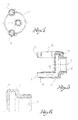
- FIG. 1 shows a perspective view
- - figure 2 shows a side view
- FIG. 5 shows a section according to the V-V arrows in Fig. 3.
- FIG. 6 shows a cross-section of a part of the body according to the VI-VI arrows in Fig. 3.
- the manifold is comprised of a block body, usually made of brass.
- the resulting body is obtained with normal forming techniques and then machined for the finish required.
- This body when finished, has a fitting 12 with an internal thread on one end and two, three or more branches on the opposite end 13; inside there is a distribution chamber 14 which connects the fitting 12 and the branches 13.
- a distribution chamber is a chamber in which the fluid passing through can be distributed between any branch of said branches 13.
- a distribution chamber is a chamber in which the fluid passing through can be shared with the branches.
- the fitting 12 has a geometric axis X; the branches 13 are in parallel Y axes to the X axis of the union part.
- this is circular and completely closed all round, coaxial with the fitting and with a radius broad enough to intersect the branches. All this to achieve the purpose and advantages described above.
Landscapes
- Engineering & Computer Science (AREA)
- Physics & Mathematics (AREA)
- Thermal Sciences (AREA)
- Mechanical Engineering (AREA)
- General Engineering & Computer Science (AREA)
- Coils Of Transformers For General Uses (AREA)
- Heat-Exchange Devices With Radiators And Conduit Assemblies (AREA)
- Fuel Cell (AREA)
- General Induction Heating (AREA)
- Reciprocating, Oscillating Or Vibrating Motors (AREA)
- Testing Of Coins (AREA)
- Valve Housings (AREA)
- Battery Mounting, Suspending (AREA)
Applications Claiming Priority (3)
| Application Number | Priority Date | Filing Date | Title |
|---|---|---|---|
| IT1999BS000076U IT247373Y1 (it) | 1999-08-02 | 1999-08-02 | Collettore monoblocco per batterie di scambio termico perventilconvettori. |
| ITBS990076U | 1999-08-02 | ||
| EP00830500A EP1074808B1 (fr) | 1999-08-02 | 2000-07-17 | Bloc collecteur pour batterie d'échange de chaleur à serpentin et ventilateur |
Related Parent Applications (1)
| Application Number | Title | Priority Date | Filing Date |
|---|---|---|---|
| EP00830500A Division EP1074808B1 (fr) | 1999-08-02 | 2000-07-17 | Bloc collecteur pour batterie d'échange de chaleur à serpentin et ventilateur |
Publications (1)
| Publication Number | Publication Date |
|---|---|
| EP1553378A2 true EP1553378A2 (fr) | 2005-07-13 |
Family
ID=11346413
Family Applications (2)
| Application Number | Title | Priority Date | Filing Date |
|---|---|---|---|
| EP05101575A Withdrawn EP1553378A2 (fr) | 1999-08-02 | 2000-07-17 | Bloc collecteur pour batterie d'échange de chaleur à serpentin et ventilateur |
| EP00830500A Expired - Lifetime EP1074808B1 (fr) | 1999-08-02 | 2000-07-17 | Bloc collecteur pour batterie d'échange de chaleur à serpentin et ventilateur |
Family Applications After (1)
| Application Number | Title | Priority Date | Filing Date |
|---|---|---|---|
| EP00830500A Expired - Lifetime EP1074808B1 (fr) | 1999-08-02 | 2000-07-17 | Bloc collecteur pour batterie d'échange de chaleur à serpentin et ventilateur |
Country Status (4)
| Country | Link |
|---|---|
| EP (2) | EP1553378A2 (fr) |
| AT (1) | ATE309515T1 (fr) |
| DE (1) | DE60023805D1 (fr) |
| IT (1) | IT247373Y1 (fr) |
Families Citing this family (1)
| Publication number | Priority date | Publication date | Assignee | Title |
|---|---|---|---|---|
| ITBS20020101A1 (it) * | 2002-11-08 | 2004-05-09 | Tiemme Raccorderie S P A | Collettore monoblocco per batterie di scambio termico di grandi |
Family Cites Families (2)
| Publication number | Priority date | Publication date | Assignee | Title |
|---|---|---|---|---|
| US4948177A (en) * | 1988-06-30 | 1990-08-14 | General Motors Corporation | Laminated fitting for heat exchanger |
| US5596877A (en) * | 1995-08-16 | 1997-01-28 | Baltimore Aircoil Company, Inc. | Header and coil arrangement for cooling apparatus |
-
1999
- 1999-08-02 IT IT1999BS000076U patent/IT247373Y1/it active
-
2000
- 2000-07-17 AT AT00830500T patent/ATE309515T1/de not_active IP Right Cessation
- 2000-07-17 DE DE60023805T patent/DE60023805D1/de not_active Expired - Lifetime
- 2000-07-17 EP EP05101575A patent/EP1553378A2/fr not_active Withdrawn
- 2000-07-17 EP EP00830500A patent/EP1074808B1/fr not_active Expired - Lifetime
Also Published As
| Publication number | Publication date |
|---|---|
| IT247373Y1 (it) | 2002-07-09 |
| ITBS990076V0 (it) | 1999-08-02 |
| EP1074808A3 (fr) | 2004-10-06 |
| EP1074808B1 (fr) | 2005-11-09 |
| DE60023805D1 (de) | 2005-12-15 |
| ATE309515T1 (de) | 2005-11-15 |
| EP1074808A2 (fr) | 2001-02-07 |
| ITBS990076U1 (it) | 2001-02-02 |
Similar Documents
| Publication | Publication Date | Title |
|---|---|---|
| US5354101A (en) | Sealing washer block connection | |
| US6070659A (en) | External connection for heat exchanger unit | |
| KR101841373B1 (ko) | 증발기를 팽창 밸브에 결합하기 위한 장치 | |
| KR101279833B1 (ko) | 엔드 커버 및 그것을 사용하는 4-방향 리버싱 밸브와 그것의 조립 방법 | |
| CN102042433B (zh) | 阀壳体坯和阀门组件 | |
| EP1074808B1 (fr) | Bloc collecteur pour batterie d'échange de chaleur à serpentin et ventilateur | |
| CN112334719B (zh) | 截止阀及其制造方法 | |
| US6869106B2 (en) | Block manifold for heat exchanger battery fan coils | |
| US20240011722A1 (en) | Heat exchanger, fin tube manufacturing method, and heat exchanger manufacturing method | |
| JP2002228072A (ja) | 二重管用継手、二重管用継手と二重管とのろう付け方法 | |
| CN218270356U (zh) | 连接管组件和换热器 | |
| CN103192243B (zh) | 形成用于热交换器的连接部分的方法 | |
| CN217784281U (zh) | 四通集成换向阀、空调器和汽车 | |
| CN223691587U (zh) | 接管组件及换热器 | |
| CN223063219U (zh) | 内流式换向阀阀芯机构及换向阀 | |
| CN205014711U (zh) | 贮液器 | |
| JP7755497B2 (ja) | 熱交換器 | |
| CN219367085U (zh) | 集成式快插接头 | |
| CN214889463U (zh) | 一种快插管接头的连接结构 | |
| JP2639987B2 (ja) | 細径金属管の接続方法 | |
| CN209876173U (zh) | 一种异形无缝钛合金管 | |
| KR200308859Y1 (ko) | 티관을 구비한 팬코일 유닛의 헤더 | |
| KR20250035906A (ko) | 다중 피치 스파이럴 유로의 열교환용 이중관 제조 방법 및 그 이중관 | |
| KR20250035905A (ko) | 스파이럴 코일을 이용한 열교환용 이중관 제조 방법 및 그 이중관 | |
| JP3750099B2 (ja) | 合成樹脂製管体の接続リング |
Legal Events
| Date | Code | Title | Description |
|---|---|---|---|
| PUAI | Public reference made under article 153(3) epc to a published international application that has entered the european phase |
Free format text: ORIGINAL CODE: 0009012 |
|
| AC | Divisional application: reference to earlier application |
Ref document number: 1074808 Country of ref document: EP Kind code of ref document: P |
|
| AK | Designated contracting states |
Kind code of ref document: A2 Designated state(s): AT BE CH CY DE DK ES FI FR GB GR IE IT LI LU MC NL PT SE |
|
| AX | Request for extension of the european patent |
Extension state: AL LT LV MK RO SI |
|
| 19A | Proceedings stayed before grant |
Effective date: 20051107 |
|
| RAP1 | Party data changed (applicant data changed or rights of an application transferred) |
Owner name: GNUTTI CIRILLO S.P.A. |
|
| 19F | Resumption of proceedings before grant (after stay of proceedings) |
Effective date: 20131202 |
|
| STAA | Information on the status of an ep patent application or granted ep patent |
Free format text: STATUS: THE APPLICATION IS DEEMED TO BE WITHDRAWN |
|
| 18D | Application deemed to be withdrawn |
Effective date: 20130201 |