EP1553380A1 - Bande de visée réglable - Google Patents
Bande de visée réglable Download PDFInfo
- Publication number
- EP1553380A1 EP1553380A1 EP04364075A EP04364075A EP1553380A1 EP 1553380 A1 EP1553380 A1 EP 1553380A1 EP 04364075 A EP04364075 A EP 04364075A EP 04364075 A EP04364075 A EP 04364075A EP 1553380 A1 EP1553380 A1 EP 1553380A1
- Authority
- EP
- European Patent Office
- Prior art keywords
- adjustable
- screws
- band
- shooting
- adjustment
- Prior art date
- Legal status (The legal status is an assumption and is not a legal conclusion. Google has not performed a legal analysis and makes no representation as to the accuracy of the status listed.)
- Withdrawn
Links
- 238000012423 maintenance Methods 0.000 abstract 1
- 230000003287 optical effect Effects 0.000 abstract 1
- 229910000831 Steel Inorganic materials 0.000 description 1
- XAGFODPZIPBFFR-UHFFFAOYSA-N aluminium Chemical compound [Al] XAGFODPZIPBFFR-UHFFFAOYSA-N 0.000 description 1
- 229910052782 aluminium Inorganic materials 0.000 description 1
- 239000002131 composite material Substances 0.000 description 1
- 239000010959 steel Substances 0.000 description 1
Images


Classifications
-
- F—MECHANICAL ENGINEERING; LIGHTING; HEATING; WEAPONS; BLASTING
- F41—WEAPONS
- F41G—WEAPON SIGHTS; AIMING
- F41G1/00—Sighting devices
- F41G1/42—Tube sights; Bar sights ; Combinations of tubular fore and rearsights
Definitions
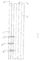
- the present invention relates to a mechanical device (1) for aiming to be mounted on hunting weapons (14) or rifle or barrel guns fig 1.
- the device according to the invention makes it possible to align its aiming (10) on the upper part of the previously adjusted band relative to the weapon (14).
- the device according to the invention is adjustable by means of the adjusting screws (2; 3 and 4) allowing adjustment in divergence with respect to the trajectory of the bale, by screwing the screws adjusting (2) and (3) and holding in opposition to pressure by means of the screw (4) fig (4), a setting in convergence with respect to the trajectory of the bullet, by screwing the screw of hold (3) and unscrew the adjusting screws (2 and 4) fig (4).
- the device according to the invention makes it possible to set the adjustment of the aiming band by pressure opposition of the adjusting screws (2 and 4) by the screw (3)
- the device according to the invention is characterized by the fact that it is monobloc, articulated in its part (9) fig (3)
- the device according to the invention is characterized by the fact that its hinge (9) of weak thickness acts as a spring blade allowing adjustment of the strip (1) according to the arrows (5 and 6).
- the device according to the invention is characterized by the fact that it is fixed on all types of weapons through the fixing screws (7 and 8) fig (3).
- the device is characterized by the fact that it is monobloc it can be composed in aluminum, steel or composite materials.
- FIG. 2 shows the band (1) on its support the barrel (12) of the weapon (14) the trajectory of the ball (15) intersects with the line of sight (10) at distances variables according to the shooting distance and the accuracy of the shooter.
- the device according to the invention has a handlebar (11) fig (3) for projecting the target on the target
- the handlebar (11) is interchangeable via the screw of the fixing screw (12)
Landscapes
- Physics & Mathematics (AREA)
- Optics & Photonics (AREA)
- Engineering & Computer Science (AREA)
- General Engineering & Computer Science (AREA)
- Aiming, Guidance, Guns With A Light Source, Armor, Camouflage, And Targets (AREA)
Abstract
L' invention concerne un dispositif permettant de tirer à des distances variables en alignant la ligne de visée (10) sur la cible. Le dispositif est adaptable sur tous types d'armes. Il est réglable en hauteur par l'intermédiaire de vis de réglage (2;3 et 4). Le maintien du réglage est assuré par opposition de pression des vis (2 et 4) par la vis (3) fig (4) Le dispositif selon l'invention caractérisé en ce qu'il comporte une bande monobloc articulée en son point (9) fig (3). Le réglage en hauteur de la bande s'effectue par l'intermédiaire des vis (2 ;3 et 4) Son réglage en hauteur s'effectue par opposition de pression des vis (2 ;3 et 4) fig (4) Le dispositif selon l'invention est particulièrement destiné à la pratique du tir rapide sportif , et du tir de chasse. Le dispositif selon l'invention peut recevoir sur sa partie supérieure de la bande (1) et tout le long de celle ci un dispositif de visée optique ou holographique. <IMAGE>
Description
La présente invention concerne un dispositif mécanique (1) de visée destiné à être monté
sur des armes de chasse (14) ou de tir à canons rayes ou lisses fig 1.
Le dispositif selon l'invention permet d'aligner sa visée (10) sur la partie supérieure de la
bande préalablement réglée par rapport à l'arme (14).
Le dispositif selon l'invention est réglable par l'intermédiaire des vis de réglage (2;3et 4)
permettant un réglage en divergence par rapport à la trajectoire de la balle , en vissant les vis
de réglage (2) et (3) et maintien par opposition de pression par l'intermédiaire de la vis (4)
fig (4), un réglage en convergence par rapport à la trajectoire de la balle, en vissant la vis de
maintien (3) et dévissant les vis de réglage (2 et 4) fig (4).
Le dispositif selon l'invention permet de fixer le réglage de la bande de visée par
opposition de pression des vis de réglage (2et4) par la vis (3)
En l'état de la technique les armes principalement rayées, disposent de systèmes de visée
classique avec hausse et guidon, cela pose un problème d'alignement rapide des organes de
visée lors de tir rapide en battue , ou de tir au débuché,rendant ces tirs rapides aléatoires.
Le dispositif selon l'invention se caractérise par le fait qu'il est monobloc, articulé en sa
partie (9) fig (3)
Le dispositif selon l'invention se caractérise par le fait que sa charnière (9) de faible
épaisseur agit telle une lame ressort permettant un réglage de la bande (1) suivant les
flèches (5 et 6).
Le dispositif selon l'invention se caractérise par le fait le fait qu'il se fixe sur tous
types d'armes par l'intermédiaire des vis de fixation (7 et 8) fig (3).
Le dispositif se caractérise par le fait qu'il est monobloc il peut être composé en
aluminium, acier ou matériaux composites.
La figure 2 montre la bande (1) sur son support le canon (12) de l'arme (14) la
trajectoire de la balle (15) est sécante avec la ligne de visée (10) à des distances
variables suivant la distance de tir et la précision du tireur.
Le dispositif selon l'invention possède un guidon (11) fig (3) permettant de projeter la
visée sur la cible
Le guidon (11) est interchangeable par l'intermédiaire de la vis de la vis de fixation (12)
- 1
- bande réglable
- 2
- vis de réglage
- 3
- vis de maintien de réglage
- 4
- vis de réglage
- 5
- réglage vers le haut
- 6
- réglage vers le bas
- 7
- vis de fixation de la bande sur canon
- 8
- vis de fixation de la bande
- 9
- charnière mécanique
- 10
- ligne de visée projetée
- 11
- guidon interchangeable et réglable en hauteur
- 12
- vis de fixation du guidon
- 13
- canon de l'arme
- 14
- arme lisse ou rayée
- 15
- trajectoire du projectile
Claims (5)
- Dispositif mécanique réglable de visée adaptable sur tous types d'armes de chasse et de tir caractérisé en ce qu'il comporte une bande 1 monobloc fixée sur le canon de l'arme.
- Dispositif selon la revendication (1) caractérisé en ce que la bande réglable présente en sa partie 9 une charnière mécanique de faible épaisseur capable de faire varier la position de la bande 1 par rapport au canon de l'arme 13 suivant les flèches 5 et 6 par l'intermédiaire des vis 2 3 4.
- Dispositif selon la revendication (1) caractérisé en ce que la bande réglable de visée est munie d'un guidon interchangeable(11), fixé à la bande (1) par la vis de fixation (12).
- Dispositif selon la revendication (3) caractérisé en ce que le guidon (11) est réglable en hauteur,il peut varier sa position verticale suivant la précision du tir et du tireur.
- Dispositif selon la revendication (1) caractérisé en ce que le système est adaptable sur tous types d'armes (14) fig (1) par l'intermédiaire des vis de fixation(7 8)
Applications Claiming Priority (2)
| Application Number | Priority Date | Filing Date | Title |
|---|---|---|---|
| FR0400170 | 2004-01-09 | ||
| FR0400170A FR2865029A1 (fr) | 2004-01-09 | 2004-01-09 | Bande de visee reglable |
Publications (1)
| Publication Number | Publication Date |
|---|---|
| EP1553380A1 true EP1553380A1 (fr) | 2005-07-13 |
Family
ID=34586482
Family Applications (1)
| Application Number | Title | Priority Date | Filing Date |
|---|---|---|---|
| EP04364075A Withdrawn EP1553380A1 (fr) | 2004-01-09 | 2004-12-06 | Bande de visée réglable |
Country Status (2)
| Country | Link |
|---|---|
| EP (1) | EP1553380A1 (fr) |
| FR (1) | FR2865029A1 (fr) |
Cited By (1)
| Publication number | Priority date | Publication date | Assignee | Title |
|---|---|---|---|---|
| EP2104828A4 (fr) * | 2007-01-08 | 2012-11-07 | Irwin Jere F | Visée de fusil de chasse et visée de pistolet ajustable |
Citations (5)
| Publication number | Priority date | Publication date | Assignee | Title |
|---|---|---|---|---|
| US3005263A (en) * | 1958-12-05 | 1961-10-24 | Savage Arms Corp | Shotgun sight |
| FR2419495A2 (fr) * | 1977-01-24 | 1979-10-05 | Mangin Roger | Bande de battue demontable |
| US4192075A (en) * | 1978-12-28 | 1980-03-11 | Strahan Travis R | Platform ramp sight for firearms |
| US4203243A (en) * | 1978-07-17 | 1980-05-20 | Hickman Jack L | Raised rib and stock elevator attachment for shotguns |
| US5443543A (en) * | 1994-09-21 | 1995-08-22 | Colt's Manufacturing Company Inc. | Firearm barrel assembly with removable sight |
-
2004
- 2004-01-09 FR FR0400170A patent/FR2865029A1/fr active Pending
- 2004-12-06 EP EP04364075A patent/EP1553380A1/fr not_active Withdrawn
Patent Citations (5)
| Publication number | Priority date | Publication date | Assignee | Title |
|---|---|---|---|---|
| US3005263A (en) * | 1958-12-05 | 1961-10-24 | Savage Arms Corp | Shotgun sight |
| FR2419495A2 (fr) * | 1977-01-24 | 1979-10-05 | Mangin Roger | Bande de battue demontable |
| US4203243A (en) * | 1978-07-17 | 1980-05-20 | Hickman Jack L | Raised rib and stock elevator attachment for shotguns |
| US4192075A (en) * | 1978-12-28 | 1980-03-11 | Strahan Travis R | Platform ramp sight for firearms |
| US5443543A (en) * | 1994-09-21 | 1995-08-22 | Colt's Manufacturing Company Inc. | Firearm barrel assembly with removable sight |
Cited By (1)
| Publication number | Priority date | Publication date | Assignee | Title |
|---|---|---|---|---|
| EP2104828A4 (fr) * | 2007-01-08 | 2012-11-07 | Irwin Jere F | Visée de fusil de chasse et visée de pistolet ajustable |
Also Published As
| Publication number | Publication date |
|---|---|
| FR2865029A1 (fr) | 2005-07-15 |
Similar Documents
| Publication | Publication Date | Title |
|---|---|---|
| US9506726B2 (en) | Accessory mounting system for firearms | |
| US12025407B2 (en) | Adjustable offset mount (AOM) | |
| US7823316B2 (en) | Adjustable gun rail lock | |
| US10288378B2 (en) | Self-leveling scope mount and method | |
| US7614805B2 (en) | Image capture device mounting assembly for firearm | |
| US7905041B1 (en) | Stabilized rifle barrel and rifle | |
| US7814699B2 (en) | Multiple sight gun sight assembly | |
| US9297613B2 (en) | Method for manufacturing sight frame attachable to handgun and sight frame attachable to handgun | |
| US7140143B1 (en) | Adjustable rifle scope mount | |
| US6868614B2 (en) | Target sight and range finder | |
| US20090049734A1 (en) | Multiple sight gun sight assembly | |
| US20190285386A1 (en) | Firearm scope mount | |
| US20090077855A1 (en) | Rifle mount | |
| US4542591A (en) | Bow sight | |
| US9395149B2 (en) | Rotating stock butt and sighting bead | |
| US9696118B2 (en) | Rear sight block for AK-type rifles | |
| US7200944B2 (en) | Pendulum bow sight | |
| US3961423A (en) | Secondary side mounted gun sight and arrangement, for auxiliary use with a primary top mounted telescope rifle sight | |
| US5305530A (en) | Archer's bow sight | |
| CN119630937A (zh) | 瞄准器安装系统、瞄准器和适配器板 | |
| EP1455158A1 (fr) | Montage d'un dispositif de visée holographique sur une arme | |
| US9052163B2 (en) | Adjustable scope mount for a projectile weapon and methods of using and making thereof | |
| US6862813B1 (en) | Laser archery bow sight | |
| US7000327B2 (en) | Compensator bow sight | |
| US20130219766A1 (en) | Method for Replacing Weapon Rear Sight with Optics |
Legal Events
| Date | Code | Title | Description |
|---|---|---|---|
| PUAI | Public reference made under article 153(3) epc to a published international application that has entered the european phase |
Free format text: ORIGINAL CODE: 0009012 |
|
| AK | Designated contracting states |
Kind code of ref document: A1 Designated state(s): AT BE BG CH CY CZ DE DK EE ES FI FR GB GR HU IE IS IT LI LT LU MC NL PL PT RO SE SI SK TR |
|
| AX | Request for extension of the european patent |
Extension state: AL BA HR LV MK YU |
|
| STAA | Information on the status of an ep patent application or granted ep patent |
Free format text: STATUS: THE APPLICATION HAS BEEN WITHDRAWN |
|
| 18W | Application withdrawn |
Effective date: 20050804 |