EP1553383B1 - Präzisionsdendrometer - Google Patents
Präzisionsdendrometer Download PDFInfo
- Publication number
- EP1553383B1 EP1553383B1 EP02781346A EP02781346A EP1553383B1 EP 1553383 B1 EP1553383 B1 EP 1553383B1 EP 02781346 A EP02781346 A EP 02781346A EP 02781346 A EP02781346 A EP 02781346A EP 1553383 B1 EP1553383 B1 EP 1553383B1
- Authority
- EP
- European Patent Office
- Prior art keywords
- dendrometer
- plant
- sensor
- bands
- bridge
- Prior art date
- Legal status (The legal status is an assumption and is not a legal conclusion. Google has not performed a legal analysis and makes no representation as to the accuracy of the status listed.)
- Expired - Lifetime
Links
- 238000005259 measurement Methods 0.000 claims abstract description 53
- 239000004411 aluminium Substances 0.000 claims description 15
- 229910052782 aluminium Inorganic materials 0.000 claims description 15
- XAGFODPZIPBFFR-UHFFFAOYSA-N aluminium Chemical compound [Al] XAGFODPZIPBFFR-UHFFFAOYSA-N 0.000 claims description 13
- 239000000463 material Substances 0.000 claims description 12
- 239000004020 conductor Substances 0.000 abstract description 6
- 230000007423 decrease Effects 0.000 abstract description 5
- 230000000694 effects Effects 0.000 description 8
- 230000008859 change Effects 0.000 description 7
- 230000003321 amplification Effects 0.000 description 4
- 238000003199 nucleic acid amplification method Methods 0.000 description 4
- 230000035945 sensitivity Effects 0.000 description 4
- 239000004952 Polyamide Substances 0.000 description 3
- 229910045601 alloy Inorganic materials 0.000 description 3
- 239000000956 alloy Substances 0.000 description 3
- 230000002457 bidirectional effect Effects 0.000 description 3
- 229920002647 polyamide Polymers 0.000 description 3
- 238000012360 testing method Methods 0.000 description 3
- 230000004075 alteration Effects 0.000 description 2
- 150000001398 aluminium Chemical class 0.000 description 2
- 230000003750 conditioning effect Effects 0.000 description 2
- 238000010586 diagram Methods 0.000 description 2
- 235000013399 edible fruits Nutrition 0.000 description 2
- 230000007613 environmental effect Effects 0.000 description 2
- 238000009434 installation Methods 0.000 description 2
- 229910000570 Cupronickel Inorganic materials 0.000 description 1
- 239000004593 Epoxy Substances 0.000 description 1
- 229910018487 Ni—Cr Inorganic materials 0.000 description 1
- 239000000853 adhesive Substances 0.000 description 1
- 230000001070 adhesive effect Effects 0.000 description 1
- 238000004873 anchoring Methods 0.000 description 1
- 238000005452 bending Methods 0.000 description 1
- 230000008901 benefit Effects 0.000 description 1
- 230000005540 biological transmission Effects 0.000 description 1
- 238000006243 chemical reaction Methods 0.000 description 1
- VNNRSPGTAMTISX-UHFFFAOYSA-N chromium nickel Chemical compound [Cr].[Ni] VNNRSPGTAMTISX-UHFFFAOYSA-N 0.000 description 1
- 230000006835 compression Effects 0.000 description 1
- 238000007906 compression Methods 0.000 description 1
- 230000008602 contraction Effects 0.000 description 1
- 238000007796 conventional method Methods 0.000 description 1
- YOCUPQPZWBBYIX-UHFFFAOYSA-N copper nickel Chemical compound [Ni].[Cu] YOCUPQPZWBBYIX-UHFFFAOYSA-N 0.000 description 1
- 238000000586 desensitisation Methods 0.000 description 1
- 230000010339 dilation Effects 0.000 description 1
- 230000005611 electricity Effects 0.000 description 1
- 230000008030 elimination Effects 0.000 description 1
- 238000003379 elimination reaction Methods 0.000 description 1
- 238000009413 insulation Methods 0.000 description 1
- 229910052742 iron Inorganic materials 0.000 description 1
- XEEYBQQBJWHFJM-UHFFFAOYSA-N iron Substances [Fe] XEEYBQQBJWHFJM-UHFFFAOYSA-N 0.000 description 1
- 230000002262 irrigation Effects 0.000 description 1
- 238000003973 irrigation Methods 0.000 description 1
- 238000004519 manufacturing process Methods 0.000 description 1
- 230000004048 modification Effects 0.000 description 1
- 238000012986 modification Methods 0.000 description 1
- PCLURTMBFDTLSK-UHFFFAOYSA-N nickel platinum Chemical compound [Ni].[Pt] PCLURTMBFDTLSK-UHFFFAOYSA-N 0.000 description 1
- ISWSIDIOOBJBQZ-UHFFFAOYSA-N phenol group Chemical group C1(=CC=CC=C1)O ISWSIDIOOBJBQZ-UHFFFAOYSA-N 0.000 description 1
- 239000004033 plastic Substances 0.000 description 1
- 239000000047 product Substances 0.000 description 1
- 239000011241 protective layer Substances 0.000 description 1
- 229920005989 resin Polymers 0.000 description 1
- 239000011347 resin Substances 0.000 description 1
- 230000004044 response Effects 0.000 description 1
- -1 simple or laminated Substances 0.000 description 1
- 239000002689 soil Substances 0.000 description 1
- 239000013589 supplement Substances 0.000 description 1
- 239000000725 suspension Substances 0.000 description 1
- 230000002277 temperature effect Effects 0.000 description 1
Images


Classifications
-
- G—PHYSICS
- G01—MEASURING; TESTING
- G01B—MEASURING LENGTH, THICKNESS OR SIMILAR LINEAR DIMENSIONS; MEASURING ANGLES; MEASURING AREAS; MEASURING IRREGULARITIES OF SURFACES OR CONTOURS
- G01B7/00—Measuring arrangements characterised by the use of electric or magnetic techniques
- G01B7/16—Measuring arrangements characterised by the use of electric or magnetic techniques for measuring the deformation in a solid, e.g. by resistance strain gauge
- G01B7/18—Measuring arrangements characterised by the use of electric or magnetic techniques for measuring the deformation in a solid, e.g. by resistance strain gauge using change in resistance
-
- G—PHYSICS
- G01—MEASURING; TESTING
- G01B—MEASURING LENGTH, THICKNESS OR SIMILAR LINEAR DIMENSIONS; MEASURING ANGLES; MEASURING AREAS; MEASURING IRREGULARITIES OF SURFACES OR CONTOURS
- G01B5/00—Measuring arrangements characterised by the use of mechanical techniques
- G01B5/0035—Measuring of dimensions of trees
Definitions
- the present invention refers to a dendrometer, that is, to an apparatus for measuring the dimensions of standing trees, in the present case generalised for the measurement of any type of plant and of any of its components, whether it be the trunk, leaves, fruit, etc.
- the dendrometer consists of a sensor that has to be placed in contact with the plant, a sensor holder through which the sensor remains secured against the above-mentioned plant, and electronics or a connection interface of the sensor with the corresponding measurement system.
- the purpose of the invention is to obtain optimum control of the dimensional changes of the plant throughout the day, so that based on the data obtained decisions can be taken to improve yield.
- linear movement sensors structured by means of an electromagnetic ring-shaped coil, in whose cavity a nucleus formed by a rod freely moves, that, due to the effect of the magnetic field of the coil, is kept constantly pressed against the surface of the plant, such as, for example, against the trunk of a tree, so that when this latter expands or contracts (a few microns a day), the nucleus or rod undergoes the equivalent axial movement generating a modification in the field of the coil, that can be perfectly measured and, using suitable conversion tables, transformed into a measurement of length.
- sensors or dendrometers based on the use of micrometrical gauges or extension measurement bands, based in turn in the fact that in all materials that are conductors of electricity a proportion exists between the length of said conductive and its electrical resistance, so that a proportion can be obtained between the relative change of length of a conductor and the change in its electrical resistance, that allows the dimensional increase or decrease of the plant being analysed to be deduced.
- the pressure dendrometer that the invention proposes being based on the conventional technique of using extension measurement bands connected so that they form a Wheatstone Bridge, satisfactorily and fully resolves the problems previously set out, assuring great precision in the measurements made by it.
- unidirectional, bidirectional or tridirectional bands form part or can form part of the dendrometer, specifically mounting a single grid on the same support, two grids orientated in positioned at right angles, or three grids in which two of them form opposite angles of 45 or 60° with respect to the third.
- Bands of the aforementioned different types can be used as resistances in the Wheatstone Bridge, so that the different orientation of such grids allows reliable data to be obtained independently of what the orientation of deformation of the bands caused by the plant may be.
- the aforementioned extension measurement bands are strategically placed wrapped in a protective layer on an aluminium sheet, of little thickness and appreciable length, with a bent section in correspondence with one of its ends, forming a part through which contact is established with the plant whose change it is required to measure, through the non-bent end this aluminium sheet is positioned onto a slot established for this purpose in a area beside a cylinder to which a connection cable is attached that has to be connected with the aluminium sheet and that at its other end is connected to an interface that is connected with the corresponding measurement system, all this forming a sensor that is complemented with an sensor holder element as a support for attachment to the corresponding plant, with the particularity that said sensor holder is fabricated in aluminium and has a number of rods acting as feet that at one of its ends is linked to a piece that semi-embraces the plant to be measured, while at the other end the feet pass through a part on which the cylinder pertaining to the sensor previously described remains supported and secured.
- connection interface forms a signal conditioning circuit by means of which a signal will be provided based on the measurement of the positive elongation starting from the rest position of the corresponding extension measurement band, a circuit that will be capable of working correctly within the supply range of 5.5 Vdc to 8 Vdc, without the output signal being affected by the variation of said supply within the range.
- the aforementioned conditioning circuit has been designed as a load cell amplifier for extension measurement bands supplied with asymmetric exact voltage, having two basic blocks, one the extension measurement bands bridge supply, and another the amplification of the bridge measurement signal of these extension measurement bands, with the particularity that the bridge supply has to have the at the maximum setting possible, since a deviation in suspension of supply would imply a deviation in the measurement, an accurate voltage regulator based on a TL431 circuit, that is an accurate Zener regulator with a maximum error of 0.5 %, being provided for that purpose, furthermore it been envisaged that at the entry of the TL431 circuit there a 5V6 zener is placed in order that the variation in supply be minimum and the error less than 0.5 %.
- the extension measurement bands are thermo-compensating for the material on which they are mounted (aluminium), because of which, in a range of 0° C to 50° C the thermal output signal is practically zero.
- an extension measurement band is formed by means of a grid (1) positioned in a support (2), a grid that forms the sensitive part for the deformation, and that must have the following characteristics:
- Materials that meet the previously outlined characteristics are polyamide, simple or laminated, and epoxy or phenolic type resins.
- the alloys used for the manufacture of bands must have, as the most important characteristic, sensitivity to deformation.
- the grid is formed by thin wire implies that it has a certain sensitivity of response to transverse deformations, especially in the areas of the loops, where there is a finite quantity of wire transversely orientated with respect to the measurement axes of the grid, as is seen in figure 1 .
- This effect is less in the bands with perpendicular section grid, but nonetheless they are inherently affected, especially if it is taken into account that every wire of the grid is sufficiently big to reflect a transverse deformation induced by the support.
- the nature and range of the consequent resistive change depends on the particular characteristics of the sensitive alloy that is used.
- extension measurement band is a resistance implies that it will become affected by the temperature variations, which obliges a compensation to minimize such an effect to be made.
- the bands can be unidirectional, as that shown one in figure 1 , that allow the condition of deformations and/or voltages of the structure onto which they are bonded to be known, according to the longitudinal axis of the band, but equally they can be bidirectional, such as that shown in figure 2 , where two grids (1) (1') are mounted on the same support (2), with their orientations at a 90° angle with respect to each other, as is also seen in the aforementioned figure 2 .
- This type of band is used when the principal directions are known and what is of interest is to know the (principal) maximum and minimum deformations and/or voltages of a structure under load, of course at the point of installation of the band.
- a mid-bridge assembly is possible, placing two extension measurement bands (3) in adjacent or opposite branches of the Wheatstone Bridge shown in figure 4 . If the bands (3) are placed in the adjacent branches, one of them must work in traction and the other in compression, in order that if the resistance increases in one it decreases in the other. Anther possibility is that one of the two presents zero deformation, that due to its positioning it operates at minimum deformation or to measure the Poisson effect.
- Adjacent branch mounting is a very useful mounting when it is intended to compensate temperature beyond, above or below the autocompensation range of the bands. In this way a band bonded onto the test structure that is measuring mechanical deformations, and those due to the thermal signal of the bands, can be had. In the adjacent branch another band, which is denominated compensation, is placed bonded onto that same material, and subjected to the same environmental conditions as the active band, but without undergoing mechanical deformations. In this way, subtracting the signal of two bands, subtracts only the deformation due to mechanical effects. Nevertheless, it is very difficult to maintain complete symmetry and that two bands are exactly at the same temperature and have the same resistance.
- the output signal is 1/2 of the band factor (K) multiplied by the deformation of the material.
- the signal is multiplied by four with respect to the quarter bridge assembly, in addition to automatic compensation with the temperature and the elimination of undesirable signals, that is, noise.
- the main advantage of the full bridge is that all of the wiring, from the point of measurement to the instrumentation, including connectors, jacks and, if they are in use, brush rings, are outside the measurement circuit, because of which the errors that they might introduce in the system are minimum.
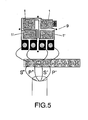
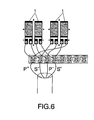
- This band is installed only in the upper face of the sensor, leaving the lower face free.
- FIG 6 the second type of sensor, of two sides, has been shown, so that two bands are placed on each side, the four grids (1) (two for each side) orienting in accordance with the principal deformation, with which an number of active branches of four is obtained. Also in this case a polyamide support and an unencapsulated grid is used, with nominal resistance of 350 ohms and autocompensation for aluminium. Each band has two parallel grids that, wired with each other and with the band placed on the other side, achieve a full bridge.
- the mounting (9) that forms the extension measurement bands is placed in a specific area of an aluminium sheet (10) of rectangular configuration and preferably of 60 mm length and 10 mm width, that at one of its ends has a double bend section with convergent lateral edges which causes that, from the first bending, the emergent part becomes narrower until terminating in an angular and rounded end (11) that is going to define the means of contact onto the corresponding plant in which the dendrometer will be applied, it having been envisaged that this aluminium sheet (10), support of the extension measurement bands previously referred to, is positioned at its opposite end in a slot (12) provided in a diametrical direction close to one of the ends of a cylindrical body (13), in accordance with is seen in figure 7 .
- the mounting referred to constitutes a sensor in connection with an electronic interface (14) that defines a circuit whose characteristics will be set out afterwards and that is connected to the corresponding measurement-taking system or equipment.
- the sensor is mounted on a support or sensor holder (15), which has a part, corresponding with the reference (15), like a clamp with a cylindrical depression in which the sensor cylinder (13) is positioned, a number of rods (16) acting as feet being passed through the part that forms that sensor holder (15), that finish in another part (17) with tightening elements to secure them, assisted by suitable anchoring elements, onto the plant (18) in which the dendrometer is applied, as is shown in figure 10 .
- a support or sensor holder which has a part, corresponding with the reference (15), like a clamp with a cylindrical depression in which the sensor cylinder (13) is positioned, a number of rods (16) acting as feet being passed through the part that forms that sensor holder (15), that finish in another part (17) with tightening elements to secure them, assisted by suitable anchoring elements, onto the plant (18) in which the dendrometer is applied, as is shown in figure 10 .
- the sensor holder (15) will be fabricated in aluminium, whereas the rods corresponding to its feet (16) are fabricated from another material with zero coefficient of expansion to allow the constant variation in microns of the plant (18) to be measured.
- the electronics interface formed by the dendrometer assembly signal adjustment circuit, is shown, a circuit that has been designed as a load cell amplifier for extension measurement bands supplied by precision asymmetric voltage, including an extension measurement bands bridge supply block (19) and an extension measurement bands bridge measurement signal amplification block (20), with the particularity that the supply block (19) has a voltage regulator based on a TL431 circuit (21) that is an accurate Zener regulator of precision with a maximum error of 0.5 %, having a 5V6 Zener (22) at the input of this block or circuit (21) in order that the variation of supply be minimum and the error less than 0.5 %, the supply referred to centering in 4.7 Vcc + 0.5 %.
- the signal amplification whose schematic diagram corresponds to the block (20), basically includes an operational (23) OPA2277/SA of low cost and high performance, operating as a differential amplifier with a set gain, set up according to the resolution required by the application, all this in a such way that the gain of the circuit will be the amplification by which the differential signal received from the extension measurement bands is multiplied, this signal being proportional to their elongation, that gain being selected on the basis of the resolution of the reader and of the accuracy required.
Landscapes
- Physics & Mathematics (AREA)
- General Physics & Mathematics (AREA)
- Life Sciences & Earth Sciences (AREA)
- Botany (AREA)
- Measurement Of Length, Angles, Or The Like Using Electric Or Magnetic Means (AREA)
- Investigating Strength Of Materials By Application Of Mechanical Stress (AREA)
- Investigating Or Analyzing Materials By The Use Of Electric Means (AREA)
- Measuring Fluid Pressure (AREA)
Claims (4)
- Präzisions-Dendrometer des Typs, der auf dem Einsatz von Dehnungsmessbändern als Widerständen für eine Wheatston'sche Brückenschaltung basiert, wobei das Dendrometer aus einem Sensorhalter, der als ein Teil zum Befestigen des Dendrometers an einer Pflanze dient, der elektronischen Schnittstelle, die ihn mit der Datenerfassungseinrichtung verbindet, und einem Sensor besteht, dadurch gekennzeichnet, dass der Sensor durch einen zylindrischen Körper (13) aus Aluminium gebildet wird, an dem ein Ende einer Aluminiumplatte (10) befestigt ist, an dem die Dehnungsmessbänder angebracht sind, und das andere Ende der Aluminiumplatte (10) in Kontakt mit der Pflanze (18) ist, um mittels des durch letztere ausgeübten Drucks ihre Dimensionsänderungen aufgrund der Verformung der Aluminiumplatte (10) und damit der Dehnungsmessbandanordnung (9) zu bestimmen.
- Präzisions-Dendrometer nach dem vorangehenden Anspruch, dadurch gekennzeichnet, dass das Ende der Aluminiumplatte (10), das in Kontakt mit der Pflanze ist, einen doppelt gebogenen Abschnitt mit aufeinander zulaufenden seitlichen Rändern hat.
- Präzisions-Dendrometer nach Anspruch 1, dadurch gekennzeichnet, dass der Sensorhalter (15) einen Teil mit einem zylindrischen Hohlraum, in dem der zylindrische Körper (13) des Sensors aufgenommen ist und gehalten wird, und eine Anzahl von Stangen (15) aufweist, die als Füße dienen und mit dem Teil des Sensorhalters (15) verbunden sind, wobei ein Teil (17) zum Anpassen und Befestigen an der Pflanze (18), an der das Dendrometer installiert ist, mit ihnen verbunden ist.
- Präzisions-Dendrometer nach Anspruch 3, dadurch gekennzeichnet, dass die Stangen (16) aus Material mit einem Nullausdehnungskoeffizienten hergestellt sind, so dass die konstante Veränderung der Pflanze (18) gemessen werden kann.
Applications Claiming Priority (1)
| Application Number | Priority Date | Filing Date | Title |
|---|---|---|---|
| PCT/ES2002/000487 WO2004036143A1 (es) | 2002-10-15 | 2002-10-15 | Dendrometro de precision |
Publications (2)
| Publication Number | Publication Date |
|---|---|
| EP1553383A1 EP1553383A1 (de) | 2005-07-13 |
| EP1553383B1 true EP1553383B1 (de) | 2011-11-30 |
Family
ID=32104071
Family Applications (1)
| Application Number | Title | Priority Date | Filing Date |
|---|---|---|---|
| EP02781346A Expired - Lifetime EP1553383B1 (de) | 2002-10-15 | 2002-10-15 | Präzisionsdendrometer |
Country Status (11)
| Country | Link |
|---|---|
| US (1) | US7398602B2 (de) |
| EP (1) | EP1553383B1 (de) |
| AR (1) | AR041542A1 (de) |
| AT (1) | ATE535775T1 (de) |
| AU (1) | AU2002349058B2 (de) |
| ES (1) | ES2379772T3 (de) |
| HN (1) | HN2003000326A (de) |
| IL (1) | IL167941A (de) |
| PA (1) | PA8584601A1 (de) |
| PT (1) | PT1553383E (de) |
| WO (1) | WO2004036143A1 (de) |
Families Citing this family (9)
| Publication number | Priority date | Publication date | Assignee | Title |
|---|---|---|---|---|
| ES2264360B1 (es) * | 2004-12-16 | 2007-11-16 | Consejo Superior Investig. Cientificas | Sistema automatico de medida del estres hidrico de arboles basado en la monitorizacion de la variacion diametral del tronco. |
| WO2011076965A1 (es) * | 2009-12-23 | 2011-06-30 | Universidad De Zaragoza | Dendrómetro electrónico |
| US9377288B2 (en) * | 2013-06-07 | 2016-06-28 | Global Change Solutions LLC | Dendrometer |
| ITTO20150046U1 (it) * | 2015-04-10 | 2016-10-10 | Guido Maisto | Dispositivo per la rilevazione di deformazioni e la trasmissione dei dati rilevati |
| CN105466328B (zh) * | 2016-01-13 | 2017-12-29 | 中国计量学院 | 高精度树木胸径测量装置 |
| US20190107380A1 (en) * | 2017-10-11 | 2019-04-11 | Sikorsky Aircraft Corporation | Strain measurement assembly |
| USD1021580S1 (en) * | 2021-12-02 | 2024-04-09 | Oregon State University | Magnetic dendrometer |
| US12092452B2 (en) * | 2021-12-02 | 2024-09-17 | Oregon State University | Magnetic dendrometer apparatus and corresponding method |
| WO2025126204A1 (en) * | 2023-12-11 | 2025-06-19 | B.G. Negev Technologies And Applications Ltd. | A dendrometer, and a method of using thereof |
Family Cites Families (19)
| Publication number | Priority date | Publication date | Assignee | Title |
|---|---|---|---|---|
| US2924019A (en) * | 1960-02-09 | Method and apparatus for measurement of | ||
| US2191808A (en) * | 1939-12-09 | 1940-02-27 | Jacob R Schramm | Tree marker |
| US2365593A (en) * | 1942-11-19 | 1944-12-19 | Westinghouse Electric & Mfg Co | Electric gauge |
| US2416664A (en) * | 1944-07-25 | 1947-02-25 | Baldwin Locomotive Works | Strain responsive apparatus |
| US2873341A (en) * | 1955-08-03 | 1959-02-10 | Kutsay Ali Umit | Electric strain gauge and resistance units therefor |
| US3937212A (en) * | 1974-12-27 | 1976-02-10 | Nasa | Miniature muscle displacement transducer |
| US4294015A (en) | 1979-12-27 | 1981-10-13 | Ecole Polytechnique | Extensometer |
| US4290311A (en) * | 1980-02-08 | 1981-09-22 | The United States Of America As Represented By The United States Department Of Energy | Dilatometer |
| US4549355A (en) * | 1984-01-04 | 1985-10-29 | Battelle Memorial Institute | Electronic dendrometer |
| GB8715436D0 (en) * | 1987-07-01 | 1987-08-05 | Ciba Geigy Ag | Substituted anthraquinones |
| US4968485A (en) * | 1987-09-25 | 1990-11-06 | Shimadzu Corporation | Arrangements for preparative route leading to water analysis |
| US5067246A (en) * | 1991-03-01 | 1991-11-26 | Feinmechanische Optische Betriebsgesellschaft M.B.H. | Gauge for measuring tree-trunk growth and the like |
| JPH0667291B2 (ja) * | 1991-03-29 | 1994-08-31 | 農林水産省森林総合研究所長 | 樹木の直径成長を測定するデンドロメータ |
| US5774999A (en) * | 1996-01-22 | 1998-07-07 | Smith; Lawson R. | Tree marker |
| US6009631A (en) * | 1996-02-27 | 2000-01-04 | Gensler; William G. | Gauge for measuring changes in the length of a perimeter |
| US5955679A (en) * | 1997-01-31 | 1999-09-21 | Liberty Technologies, Inc. | Device for measuring strain parameters of a generally cylindrical member of virtually any size |
| US6185833B1 (en) * | 1998-01-27 | 2001-02-13 | Yissum Research Development Company Of The Hebrew University Of Jerusalem | Leaf thickness sensing device |
| US6758098B1 (en) * | 2002-02-20 | 2004-07-06 | The United States Of America As Represented By The Administrator Of The National Aeronautics And Space Administration | Force-measuring clamp |
| US7207230B2 (en) * | 2003-05-22 | 2007-04-24 | Crane Nuclear, Inc. | High-stability instrument mounting system for repeatable field testing of equipment |
-
2002
- 2002-10-15 AU AU2002349058A patent/AU2002349058B2/en not_active Ceased
- 2002-10-15 ES ES02781346T patent/ES2379772T3/es not_active Expired - Lifetime
- 2002-10-15 AT AT02781346T patent/ATE535775T1/de active
- 2002-10-15 WO PCT/ES2002/000487 patent/WO2004036143A1/es not_active Ceased
- 2002-10-15 EP EP02781346A patent/EP1553383B1/de not_active Expired - Lifetime
- 2002-10-15 US US10/531,312 patent/US7398602B2/en not_active Expired - Fee Related
- 2002-10-15 PT PT02781346T patent/PT1553383E/pt unknown
-
2003
- 2003-10-06 PA PA20038584601A patent/PA8584601A1/es unknown
- 2003-10-07 AR ARP030103646A patent/AR041542A1/es unknown
- 2003-10-15 HN HN2003000326A patent/HN2003000326A/es unknown
-
2005
- 2005-04-10 IL IL167941A patent/IL167941A/en not_active IP Right Cessation
Also Published As
| Publication number | Publication date |
|---|---|
| IL167941A (en) | 2010-04-15 |
| PT1553383E (pt) | 2012-03-19 |
| ATE535775T1 (de) | 2011-12-15 |
| ES2379772T3 (es) | 2012-05-03 |
| HN2003000326A (es) | 2005-01-27 |
| PA8584601A1 (es) | 2004-05-26 |
| WO2004036143A1 (es) | 2004-04-29 |
| EP1553383A1 (de) | 2005-07-13 |
| US20060123647A1 (en) | 2006-06-15 |
| US7398602B2 (en) | 2008-07-15 |
| AU2002349058B2 (en) | 2009-12-24 |
| AU2002349058A1 (en) | 2004-05-04 |
| AR041542A1 (es) | 2005-05-18 |
Similar Documents
| Publication | Publication Date | Title |
|---|---|---|
| US4064744A (en) | Strain sensorextensiometer | |
| JP3792274B2 (ja) | 複数のせん断ひずみゲージを用いた六軸力センサ | |
| CA1131043A (en) | Strain gage pick-up and method for adjusting such strain gage pick-up | |
| GB2369889A (en) | Strain sensing device | |
| EP1553383B1 (de) | Präzisionsdendrometer | |
| CN1122631A (zh) | 具有完整温度信号的应变仪传感器 | |
| KR100414516B1 (ko) | 스트레인 게이지 스트립 및 그의 적용 장치 | |
| US4523461A (en) | Hot wire anemometer | |
| WO2001014892A1 (en) | Beam strain gauge | |
| CN105628269B (zh) | 一种微力及微位移放大传感器 | |
| EP0502658A1 (de) | Dimensionsmessvorrichtung | |
| US4604895A (en) | Hot wire anemometer | |
| US3448607A (en) | Strain gauge temperature compensation system | |
| CN1399122A (zh) | 一种对应变式称重传感器进行温度补偿的方法 | |
| Dorsey | Homegrown strain-gage transducers: Simple compensation procedures can be used to correct errors in strain-gage transducer bridges | |
| US20060288795A1 (en) | Strain gage with off axis creep compensation feature | |
| CN104457549B (zh) | 一种裂缝宽度自动监测装置 | |
| ZA200503596B (en) | Precision dendrometer | |
| JP3534205B2 (ja) | ひずみゲージ式変換器における過渡温度特性の補償回路およびその補償方法 | |
| CA1309879C (en) | Pressure transducer using thick film resistor | |
| US5591917A (en) | Semiconductor pressure sensor with rated pressure specified for desired error of linearity | |
| Abu-Mahfouz | Strain Gauge | |
| CN119343585A (zh) | 应变仪表传感器 | |
| TN | Bondable resistance temperature sensors and associated circuitry | |
| Tuttle | Resistive strain measurement devices |
Legal Events
| Date | Code | Title | Description |
|---|---|---|---|
| PUAI | Public reference made under article 153(3) epc to a published international application that has entered the european phase |
Free format text: ORIGINAL CODE: 0009012 |
|
| 17P | Request for examination filed |
Effective date: 20050420 |
|
| AK | Designated contracting states |
Kind code of ref document: A1 Designated state(s): AT BE BG CH CY CZ DE DK EE ES FI FR GB GR IE IT LI LU MC NL PT SE SK TR |
|
| AX | Request for extension of the european patent |
Extension state: AL LT LV MK RO SI |
|
| DAX | Request for extension of the european patent (deleted) | ||
| 17Q | First examination report despatched |
Effective date: 20070323 |
|
| GRAP | Despatch of communication of intention to grant a patent |
Free format text: ORIGINAL CODE: EPIDOSNIGR1 |
|
| RAP1 | Party data changed (applicant data changed or rights of an application transferred) |
Owner name: VERDTECH NUEVO CAMPO, S.A. |
|
| GRAS | Grant fee paid |
Free format text: ORIGINAL CODE: EPIDOSNIGR3 |
|
| GRAA | (expected) grant |
Free format text: ORIGINAL CODE: 0009210 |
|
| AK | Designated contracting states |
Kind code of ref document: B1 Designated state(s): AT BE BG CH CY CZ DE DK EE ES FI FR GB GR IE IT LI LU MC NL PT SE SK TR |
|
| REG | Reference to a national code |
Ref country code: GB Ref legal event code: FG4D Ref country code: CH Ref legal event code: EP |
|
| REG | Reference to a national code |
Ref country code: IE Ref legal event code: FG4D |
|
| REG | Reference to a national code |
Ref country code: DE Ref legal event code: R096 Ref document number: 60241679 Country of ref document: DE Effective date: 20120209 |
|
| REG | Reference to a national code |
Ref country code: NL Ref legal event code: VDEP Effective date: 20111130 |
|
| REG | Reference to a national code |
Ref country code: PT Ref legal event code: SC4A Free format text: AVAILABILITY OF NATIONAL TRANSLATION Effective date: 20120306 |
|
| REG | Reference to a national code |
Ref country code: ES Ref legal event code: FG2A Ref document number: 2379772 Country of ref document: ES Kind code of ref document: T3 Effective date: 20120503 |
|
| PG25 | Lapsed in a contracting state [announced via postgrant information from national office to epo] |
Ref country code: GR Free format text: LAPSE BECAUSE OF FAILURE TO SUBMIT A TRANSLATION OF THE DESCRIPTION OR TO PAY THE FEE WITHIN THE PRESCRIBED TIME-LIMIT Effective date: 20120301 Ref country code: BE Free format text: LAPSE BECAUSE OF FAILURE TO SUBMIT A TRANSLATION OF THE DESCRIPTION OR TO PAY THE FEE WITHIN THE PRESCRIBED TIME-LIMIT Effective date: 20111130 Ref country code: NL Free format text: LAPSE BECAUSE OF FAILURE TO SUBMIT A TRANSLATION OF THE DESCRIPTION OR TO PAY THE FEE WITHIN THE PRESCRIBED TIME-LIMIT Effective date: 20111130 Ref country code: SE Free format text: LAPSE BECAUSE OF FAILURE TO SUBMIT A TRANSLATION OF THE DESCRIPTION OR TO PAY THE FEE WITHIN THE PRESCRIBED TIME-LIMIT Effective date: 20111130 |
|
| PG25 | Lapsed in a contracting state [announced via postgrant information from national office to epo] |
Ref country code: CY Free format text: LAPSE BECAUSE OF FAILURE TO SUBMIT A TRANSLATION OF THE DESCRIPTION OR TO PAY THE FEE WITHIN THE PRESCRIBED TIME-LIMIT Effective date: 20111130 |
|
| PG25 | Lapsed in a contracting state [announced via postgrant information from national office to epo] |
Ref country code: DK Free format text: LAPSE BECAUSE OF FAILURE TO SUBMIT A TRANSLATION OF THE DESCRIPTION OR TO PAY THE FEE WITHIN THE PRESCRIBED TIME-LIMIT Effective date: 20111130 Ref country code: SK Free format text: LAPSE BECAUSE OF FAILURE TO SUBMIT A TRANSLATION OF THE DESCRIPTION OR TO PAY THE FEE WITHIN THE PRESCRIBED TIME-LIMIT Effective date: 20111130 Ref country code: EE Free format text: LAPSE BECAUSE OF FAILURE TO SUBMIT A TRANSLATION OF THE DESCRIPTION OR TO PAY THE FEE WITHIN THE PRESCRIBED TIME-LIMIT Effective date: 20111130 Ref country code: BG Free format text: LAPSE BECAUSE OF FAILURE TO SUBMIT A TRANSLATION OF THE DESCRIPTION OR TO PAY THE FEE WITHIN THE PRESCRIBED TIME-LIMIT Effective date: 20120229 Ref country code: CZ Free format text: LAPSE BECAUSE OF FAILURE TO SUBMIT A TRANSLATION OF THE DESCRIPTION OR TO PAY THE FEE WITHIN THE PRESCRIBED TIME-LIMIT Effective date: 20111130 |
|
| PG25 | Lapsed in a contracting state [announced via postgrant information from national office to epo] |
Ref country code: IT Free format text: LAPSE BECAUSE OF FAILURE TO SUBMIT A TRANSLATION OF THE DESCRIPTION OR TO PAY THE FEE WITHIN THE PRESCRIBED TIME-LIMIT Effective date: 20111130 |
|
| REG | Reference to a national code |
Ref country code: AT Ref legal event code: MK05 Ref document number: 535775 Country of ref document: AT Kind code of ref document: T Effective date: 20111130 |
|
| PLBE | No opposition filed within time limit |
Free format text: ORIGINAL CODE: 0009261 |
|
| STAA | Information on the status of an ep patent application or granted ep patent |
Free format text: STATUS: NO OPPOSITION FILED WITHIN TIME LIMIT |
|
| 26N | No opposition filed |
Effective date: 20120831 |
|
| REG | Reference to a national code |
Ref country code: DE Ref legal event code: R097 Ref document number: 60241679 Country of ref document: DE Effective date: 20120831 |
|
| PG25 | Lapsed in a contracting state [announced via postgrant information from national office to epo] |
Ref country code: AT Free format text: LAPSE BECAUSE OF FAILURE TO SUBMIT A TRANSLATION OF THE DESCRIPTION OR TO PAY THE FEE WITHIN THE PRESCRIBED TIME-LIMIT Effective date: 20111130 |
|
| PG25 | Lapsed in a contracting state [announced via postgrant information from national office to epo] |
Ref country code: MC Free format text: LAPSE BECAUSE OF NON-PAYMENT OF DUE FEES Effective date: 20121031 |
|
| REG | Reference to a national code |
Ref country code: CH Ref legal event code: PL |
|
| GBPC | Gb: european patent ceased through non-payment of renewal fee |
Effective date: 20121015 |
|
| PG25 | Lapsed in a contracting state [announced via postgrant information from national office to epo] |
Ref country code: FI Free format text: LAPSE BECAUSE OF FAILURE TO SUBMIT A TRANSLATION OF THE DESCRIPTION OR TO PAY THE FEE WITHIN THE PRESCRIBED TIME-LIMIT Effective date: 20111130 |
|
| REG | Reference to a national code |
Ref country code: IE Ref legal event code: MM4A |
|
| PG25 | Lapsed in a contracting state [announced via postgrant information from national office to epo] |
Ref country code: LI Free format text: LAPSE BECAUSE OF NON-PAYMENT OF DUE FEES Effective date: 20121031 Ref country code: GB Free format text: LAPSE BECAUSE OF NON-PAYMENT OF DUE FEES Effective date: 20121015 Ref country code: CH Free format text: LAPSE BECAUSE OF NON-PAYMENT OF DUE FEES Effective date: 20121031 Ref country code: IE Free format text: LAPSE BECAUSE OF NON-PAYMENT OF DUE FEES Effective date: 20121015 |
|
| PG25 | Lapsed in a contracting state [announced via postgrant information from national office to epo] |
Ref country code: TR Free format text: LAPSE BECAUSE OF FAILURE TO SUBMIT A TRANSLATION OF THE DESCRIPTION OR TO PAY THE FEE WITHIN THE PRESCRIBED TIME-LIMIT Effective date: 20111130 |
|
| PG25 | Lapsed in a contracting state [announced via postgrant information from national office to epo] |
Ref country code: LU Free format text: LAPSE BECAUSE OF NON-PAYMENT OF DUE FEES Effective date: 20121015 |
|
| REG | Reference to a national code |
Ref country code: FR Ref legal event code: PLFP Year of fee payment: 14 |
|
| PGFP | Annual fee paid to national office [announced via postgrant information from national office to epo] |
Ref country code: DE Payment date: 20151015 Year of fee payment: 14 |
|
| PGFP | Annual fee paid to national office [announced via postgrant information from national office to epo] |
Ref country code: FR Payment date: 20151029 Year of fee payment: 14 |
|
| REG | Reference to a national code |
Ref country code: DE Ref legal event code: R119 Ref document number: 60241679 Country of ref document: DE |
|
| REG | Reference to a national code |
Ref country code: FR Ref legal event code: ST Effective date: 20170630 |
|
| PG25 | Lapsed in a contracting state [announced via postgrant information from national office to epo] |
Ref country code: FR Free format text: LAPSE BECAUSE OF NON-PAYMENT OF DUE FEES Effective date: 20161102 Ref country code: DE Free format text: LAPSE BECAUSE OF NON-PAYMENT OF DUE FEES Effective date: 20170503 |
|
| PG25 | Lapsed in a contracting state [announced via postgrant information from national office to epo] |
Ref country code: PT Free format text: LAPSE BECAUSE OF NON-PAYMENT OF DUE FEES Effective date: 20180416 |
|
| PGFP | Annual fee paid to national office [announced via postgrant information from national office to epo] |
Ref country code: PT Payment date: 20191011 Year of fee payment: 18 |
|
| PGFP | Annual fee paid to national office [announced via postgrant information from national office to epo] |
Ref country code: ES Payment date: 20191129 Year of fee payment: 18 |
|
| PG25 | Lapsed in a contracting state [announced via postgrant information from national office to epo] |
Ref country code: PT Free format text: LAPSE BECAUSE OF NON-PAYMENT OF DUE FEES Effective date: 20210415 |
|
| REG | Reference to a national code |
Ref country code: ES Ref legal event code: FD2A Effective date: 20220121 |
|
| PG25 | Lapsed in a contracting state [announced via postgrant information from national office to epo] |
Ref country code: ES Free format text: LAPSE BECAUSE OF NON-PAYMENT OF DUE FEES Effective date: 20201016 |