EP1553393B1 - Dispositif pour appliquer des impacts de faible vitesse à des structures mécaniques - Google Patents
Dispositif pour appliquer des impacts de faible vitesse à des structures mécaniques Download PDFInfo
- Publication number
- EP1553393B1 EP1553393B1 EP04380283A EP04380283A EP1553393B1 EP 1553393 B1 EP1553393 B1 EP 1553393B1 EP 04380283 A EP04380283 A EP 04380283A EP 04380283 A EP04380283 A EP 04380283A EP 1553393 B1 EP1553393 B1 EP 1553393B1
- Authority
- EP
- European Patent Office
- Prior art keywords
- impactor
- launcher
- machine
- low velocity
- mechanical structures
- Prior art date
- Legal status (The legal status is an assumption and is not a legal conclusion. Google has not performed a legal analysis and makes no representation as to the accuracy of the status listed.)
- Expired - Lifetime
Links
Images


Classifications
-
- G—PHYSICS
- G01—MEASURING; TESTING
- G01N—INVESTIGATING OR ANALYSING MATERIALS BY DETERMINING THEIR CHEMICAL OR PHYSICAL PROPERTIES
- G01N3/00—Investigating strength properties of solid materials by application of mechanical stress
- G01N3/30—Investigating strength properties of solid materials by application of mechanical stress by applying a single impulsive force, e.g. by falling weight
- G01N3/307—Investigating strength properties of solid materials by application of mechanical stress by applying a single impulsive force, e.g. by falling weight generated by a compressed or tensile-stressed spring; generated by pneumatic or hydraulic means
-
- G—PHYSICS
- G01—MEASURING; TESTING
- G01M—TESTING STATIC OR DYNAMIC BALANCE OF MACHINES OR STRUCTURES; TESTING OF STRUCTURES OR APPARATUS, NOT OTHERWISE PROVIDED FOR
- G01M7/00—Vibration-testing of structures; Shock-testing of structures
- G01M7/08—Shock-testing
-
- G—PHYSICS
- G01—MEASURING; TESTING
- G01N—INVESTIGATING OR ANALYSING MATERIALS BY DETERMINING THEIR CHEMICAL OR PHYSICAL PROPERTIES
- G01N2203/00—Investigating strength properties of solid materials by application of mechanical stress
- G01N2203/0001—Type of application of the stress
- G01N2203/001—Impulsive
-
- G—PHYSICS
- G01—MEASURING; TESTING
- G01N—INVESTIGATING OR ANALYSING MATERIALS BY DETERMINING THEIR CHEMICAL OR PHYSICAL PROPERTIES
- G01N2203/00—Investigating strength properties of solid materials by application of mechanical stress
- G01N2203/0014—Type of force applied
- G01N2203/0016—Tensile or compressive
- G01N2203/0019—Compressive
-
- G—PHYSICS
- G01—MEASURING; TESTING
- G01N—INVESTIGATING OR ANALYSING MATERIALS BY DETERMINING THEIR CHEMICAL OR PHYSICAL PROPERTIES
- G01N2203/00—Investigating strength properties of solid materials by application of mechanical stress
- G01N2203/003—Generation of the force
- G01N2203/0042—Pneumatic or hydraulic means
- G01N2203/0044—Pneumatic means
Definitions
- the present invention concerns a machine for applying low velocity impacts to mechanical structures, being a compact and high precision machine, offering a wide range of energies, the impacts being able to be applied from the interior and from the exterior of a complete or specimen structure, from any angle of incidence and measuring the energy delivered and that returned.
- the machine for applying low velocity impacts to mechanical structures forming the object of the invention transforms the internal energy accumulated in a small. tank of compressed air (hereinafter called the drum) into the kinetic energy of a mass which impacts (hereinafter called the impactor).
- the drum a small. tank of compressed air
- the impactor the kinetic energy of a mass which impacts
- the machine that we are concerned with includes three main mechanical blocks:
- the impactor, the launcher and the base structure are joined by the mechanism of the firing device.
- the pneumatic circuits are fully discharged.
- the control system reports on the "false impact” and tells the operator the steps to follow.
- the machine is pneumatically operated in "open cycle” (low cost, low weight and compact construction).
- the structure of the machine also avoids "secondary impacts
- the bar 2 incorporates the impactor head 3 at its front end, and the piston-valve-spring assembly at the other end. This assembly is referenced in general with number 4; the piston itself is referenced with number 5 and the spring with number 6.
- Also shown in this figure 1 is the laser head 9, among other component elements.
- Shown in figure 2 is another of the main mechanical blocks of the machine, which we have been calling the launcher and which includes the sleeve 10 of the pneumatic cylinder which is completed with the piston 5 of the rear part of the impactor 1.
- the launcher is referenced in general with number 11.
- the sleeve 10 of the pneumatic cylinder for propulsion of the impactor 1 has two symmetric side windows 12 through which the ends of the valve retainer (referenced with 13 in figure 5 ) pass, in any position of the travel of the launcher 11. Its rear end remains closed with the cover 14 and its front end is extended in the main tube 15.
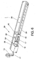
- the cover 14 is fixed to the tubular sleeve 10 of the propulsion cylinder, with the interposition of a sealing ring. It includes the pneumatic connection (flexible) to the drum (not represented) as well as the securing point 16 of one of the rods 17 (see figure 6 ) of the respective piston of the residual energy absorber device, shown in this figure 6 .
- the reference 18 labels one of these pistons.
- the main tube 15 is the support for the firing assembly which we will be seeing later on in relation to figure 4 . It possesses two symmetric side windows 19 for the passage of the retaining yoke 20 (see figure 5 ) of the emergency energy absorber device, referenced in general with number 21 in this figure 5 . It also has another upper window 22 for the passage of the laser beam of the velocity measurement system, of which the laser head 9 of figure 1 forms part. It also includes two side windows 23, aligned with those referenced with 19 which are located further back than the latter, through which they pass, and are linked together the two pivoting levers or catches 24 of the firing assembly, which we will be talking about in relation to figure 4 .
- the main tube 15 houses at its ends the air cushion bearings 25, along with the fittings 26 supporting the runners of the linear bearing, linking the launcher 11 to the base structure which we can see in figure 3 and whose features will be commented below.
- the base structure is referenced in general with number 27 and consists of the basic piece 28 in a "U" shape (in this figure 3 just one of its longitudinal halves has been represented so that its internal elements can be seen).
- the equipment platform, the equipment and the ducting and cabling are not represented since they are known in themselves.
- the "U” piece 28 is integral with the rail 29 of the linear bearing on which the launcher 11 slides, provided for that purpose with the fittings 26, inside which a bridge-shape can be distinguished.
- the "U" piece 28 also includes two special symmetric fittings, referenced with number 30 and which include the securing drill-holes 31 for the valve retainer 13 (see figure 5 ), by means of the stud 32; also including the securing holes 33 for the absorber module 34 of the emergency energy absorber device 21 (see figure 5 ); also being provided with some holes 35 for securing of the supports 36 for the laser head 9 (see figure 1 ). Also joined to the "U" piece 28 of the base structure 27 via the drill-holes 37 made in its core are the cylinders 38 of the residual energy absorber device (see figure 6 ), about which we will be talking further below, and which is in general referenced with number 39 in this figure 6 .
- the main tube 15 can optionally include ballast pieces (not represented in the figures) for improving the response of the machine in the upper range of energies.
- the firing assembly referenced in general with number 41. It includes a body 42 fixed to the launcher 11, which incorporates a cylinder-piston for operating the firing mechanism; two actuators 43 in the form of an "L", each of which includes a lug 44 which retains/releases the securing between the launcher 11 and the base structure 27. The lug 44 enters the hole 45 (see figure 5 ). Each of these actuators 43 presses on the pivoting lever or catch 24 mentioned earlier.
- the firing operation is commenced pneumatically and the effect is dual: to withdraw the said lugs 44 and to release the impactor 1 when the two pivoting levers 24, that were retaining it by means of the flange 7 (see figures 1 and 4 ), are removed.
- These housings in the flange 7 are referenced with number 46.
- the pistons 18 are integrally joined via their rods 17 to the launcher 11 by means of the cover 14 and the piece 40.
- the pistons 18 are initially centered in their respective cylinders 38, permitting the same displacement in both directions.
- the movement of the launcher 11 in relation to the base 27 generates a very small reaction force in the first part of the movement which grows sharply when the cavity that is reduced has a size very much less than at the beginning.
- This type of profile of the pressure is very convenient for not transmitting any perturbation to the base in the first phase and guaranteeing a smooth braking.
- the angle of the impact, for establishing the particular pre-charge pressure of each chamber is considered.
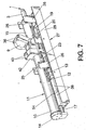
- FIG 5 which shows the emergency device 21, when the travel of the impactor 1 exceeds the rated limit by a small distance the flange 7 integral with the bar 2 is inserted into the yoke 20, specifically into the tronco-conical seating 55. Via its two ends, the yoke 20 pulls on the respective absorber blocks 34 which, due to being secured to the base 27 (specifically to the two paired fittings 30), transmit to it the energy not absorbed by them. This residual energy is a function of the ratio of the mass of the impactor and the base.
- the flange 7 In order to measure the velocity of the impactor 1 by means of the laser device 9, provision has been made for the flange 7 to have a planed surface on its conical part 57.
- the laser head 9 sees the bar of the impactor all the time during the acceleration phase. Only during the interval provided for the measurement does the plane face 56 of the flange 7 function as a mirror. As we said earlier, the laser device takes at least three guaranteed samples, thereby obtaining a precise measurement of the velocity.
- the reference 58 shows a vertical hole which is crossed with the geometric axis of the launcher 11 and which vertically traverses the window 23 for location of the rotating pin 59 (see figure 4 ) of the pivoting levers or catches 24 which are retained in the housings 46 of the flange 7 of the impactor 1.
- referenced with number 60 is the O-ring seal of piston 5 arranged in a floating position in order to minimise friction.
Landscapes
- Physics & Mathematics (AREA)
- General Physics & Mathematics (AREA)
- General Health & Medical Sciences (AREA)
- Chemical & Material Sciences (AREA)
- Analytical Chemistry (AREA)
- Biochemistry (AREA)
- Life Sciences & Earth Sciences (AREA)
- Health & Medical Sciences (AREA)
- Immunology (AREA)
- Pathology (AREA)
- Investigating Strength Of Materials By Application Of Mechanical Stress (AREA)
- Valve Device For Special Equipments (AREA)
- Transition And Organic Metals Composition Catalysts For Addition Polymerization (AREA)
- Valve-Gear Or Valve Arrangements (AREA)
- Aerodynamic Tests, Hydrodynamic Tests, Wind Tunnels, And Water Tanks (AREA)
Claims (10)
- Dispositif pour appliquer des impacts de faible vitesse à des structures mécaniques, dans une large gamme d'énergies à partir de l'intérieur et à partir de l'extérieur, à n'importe quel angle d'incidence, et mesurer l'énergie appliquée et celle absorbée et avec un cycle opératoire très court, caractérisé en ce qu'il comprend un élément d'impacteur (1) joint à un élément de lanceur (11) et tous les deux joints à leur tour à une structure de base (27) au moyen de plusieurs cliquets (24) et actionneurs (43) activés par le -système de commande du dispositif, l'impacteur (1) se présentant sous la forme d'une barre cylindrique (2) avec une extrémité avant (3) pour l'impact, une bride (7) dans son corps central et une extrémité arrière dans laquelle l'ensemble de soupape (4) doit se trouver, ensemble dont le piston (5) est joint à un corps tubulaire (47) qui coulisse dans la section arrière de la barre (2) de l'impacteur (1), et dont le manchon (10) du cylindre de propulsion constitue la partie arrière du tube de lanceur (11), le piston (5) étant aidé par un ressort (6) qui absorbe le rebond; comprenant un système d'absorbeur d'énergie résiduelle (39) dans lequel les deux chambres de deux cylindres pneumatique (38) sont chargées à une certaine pression, l'impacteur (1) étant amorcé en étant déplacé à l'intérieur du lanceur (11) jusqu'à ce qu'il soit retenu par plusieurs cliquets pivotants (24), l'impact étant réalisé en-actiorinant un mécanisme de tir (41).
- Dispositif pour appliquer des impacts de faible vitesse à des structures mécaniques selon la revendication 1, caractérisé en ce que l'élément de lanceur (11) comprend le tube ou le manchon (10) du cylindre pneumatique du système de propulsion, le long de l'intérieur duquel l'impacteur (1) coulisse, le tube ou le manchon (10) comportant deux fenêtres latérales (12) pour le passage du dispositif de retenue de soupape (13), et étant fermé à une de ses extrémités au moyen d'un couvercle (14) et étant connecté par l'intermédiaire de son autre extrémité à un tube principal ou d'extension (15), qui sert de support à l'ensemble de tir (41), ce tube principal (15) comportant deux fenêtres latérales (19) pour le passage de l'étrier de retenue (20) de l'absorbeur d'énergie de secours (39), et une autre fenêtre supérieure (22) prévue pour le passage du laser du système de mesure de la vitesse par laser (9); ce tube principal (15) contenant dans ses extrémités les paliers du coussin d'air (25) et les raccords (26) qui supportent les rails du palier joignant le lanceur (11) à la base (27).
- Dispositif pour appliquer des impacts de faible vitesse à des structures mécaniques selon la revendication 1, caractérisé en ce que la structure de base (27) qui supporte l'impacteur (1) et le lanceur ((11) est constituée d'une pièce de support de base (28) en forme de "U" qui porte de façon intégrée à celle-ci le rail (29) du palier linéaire sur lequel le lanceur (11) coulisse par l'intermédiaire de ses raccords (26); deux raccords latéraux symétriques (30) auxquels le dispositif de retenue de soupape (13), le module d'absorbeur (34) du dispositif d'absorbeur de secours (21) et le dispositif de laser (9) sont attachés.
- Dispositif pour appliquer des impacts de faible vitesse à des structures mécaniques selon la revendication 1, caractérisé en ce que l'ensemble ou le mécanisme de tir (41) élimine les connexions entre l'impacteur (1), le lanceur (11) et la base (27), permettant le déplacement de l'impacteur (1) et du lanceur (11) dans des directions opposées, soumis à la pression du tambour; comprenant un corps (42) fixé au lanceur (11) qui incorpore un ensemble cylindre - piston pour l'opération de tir; deux actionneurs (43) en forme de "L" présentant des saillies séparées (44) pour la fixation - la séparation par rapport à la base (27), comportant le trou de fixation respectif (45), ces actionneurs (43) étant à leur tour pressés sur un levier pivotant respectif (24); avec les goujons (44) qui sont retirés au moment du tir, et les leviers pivotants (24) qui sont tournés dans le but de libérer la retenue exercée sur la bride (2).
- Dispositif pour appliquer des impacts de faible vitesse à des structures mécaniques selon la revendication 1, caractérisé en ce que l'ensemble soupape - piston (4-5) de l'extrémité arrière de l'impacteur (1), assisté par le ressort (6) et la pression dans la chambre, force le piston (5) à exercer une poussée contre la barre (2) de celui-ci, fermant le passage conique (48) qui est formé entre un appui conique dans le goulot du corps tubulaire (47) et un élargissement conique dans la barre (2) elle-même; ce passage conique (48) étant ouvert lorsque le corps (47) est retenu par le dispositif de retenue de soupape (13) qui passe à travers les fenêtres latérales (12) du tube (10) du lanceur (11), dans le but d'être déchargé dans l'atmosphère par l'intermédiaire de plusieurs trous de forage (49) dans la paroi du tube (47) de l'unité de soupape (4), l'impacteur (1) continuant son déplacement linéaire contre le ressort (6) qui garantit qu'après l'impact, il n'y aura pas de second impact qui suivra le rebond.
- Dispositif pour appliquer des impacts de faible vitesse à des structures mécaniques selon la revendication 5, caractérisé en ce que le corps tubulaire (97) du cylindre pneumatique coulisse dans la barre (2) de l'impacteur (1) par l'intermédiaire de deux rondelles anti-friction (50, 51); et le piston (5) possède un joint torique (60) agencé en mode flottant.
- Dispositif pour appliquer des impacts de faible vitesse à des structures mécaniques selon la revendication 1; caractérisé en ce que, pendant l'application de l'impact, l'énergie fournie lors de la dilatation est distribuée entre l'impacteur (1) et le lanceur (11) sans être transmise à la base (27), la vitesse du rebond étant mesurée après l'impact et le laceur (11) étant retenu au moyen d'un dispositif d'absorbeur d'énergie résiduelle (9) .
- Dispositif pour appliquer des impacts de faible vitesse à des structures mécaniques selon la revendication 7, caractérisé en ce que le dispositif d'absorbeur d'énergie résiduelle (39) comprend deux corps (38) ou manchons d'un cylindre pneumatique monté un sur chaque côté d'un corps central (54) à partir duquel la chambre de chaque cylindre, qui est jointe à la structure de base, est chargée à la pression appropriée; les pistons (18) de chaque corps de cylindre (38) étant intégrés à une tige respective (17) dont les extrémités sont connectées au couvercle (14) du lanceur (11) et à la pièce (40) intégrée au raccord correspondant (26), les déplacements linéaires du lanceur (11) se poursuivant de cette manière.
- Dispositif pour appliquer des impacts de faible vitesse à des structures mécaniques selon la revendication 1, caractérisé en ce qu'il existe également un dispositif d'absorbeur d'énergie de secours (21), si la structure qui est sur le point de recevoir l'impact est positionnée à l'extérieur de la portée du dispositif, ledit dispositif recevant la totalité de l'énergie cinétique de l'impacteur (1), la bride (7) du corps (2) de l'impacteur (1) frappant ensuite un étrier (20) qui forme de façon centrale un appui de récepteur conique (55), les extrémités de l'étrier (20) étant connectées à des blocs d'absorbeur collatéraux séparés (34) reliés au raccord (30) de la base (27).
- Dispositif pour appliquer des impacts de faible vitesse à des structures mécaniques selon les revendications 1 et 3, caractérisé en ce que le dispositif de laser (9) pour mesurer la vitesse de l'impact mesure des distances courtes à cause de la bride conique (7) qui présente une face plane (56) dans sa surface supérieure, de telle sorte que la tête de laser (9) voie celle-ci agir comme un miroir et échantillonne la distance à des intervalles de temps fixes, déterminant ainsi la vitesse.
Applications Claiming Priority (2)
| Application Number | Priority Date | Filing Date | Title |
|---|---|---|---|
| ES200303088 | 2003-12-31 | ||
| ES200303088A ES2247901B1 (es) | 2003-12-31 | 2003-12-31 | Maquina para aplicar impactos de baja velocidad a estructuras mecanicas. |
Publications (2)
| Publication Number | Publication Date |
|---|---|
| EP1553393A1 EP1553393A1 (fr) | 2005-07-13 |
| EP1553393B1 true EP1553393B1 (fr) | 2009-08-26 |
Family
ID=34586135
Family Applications (1)
| Application Number | Title | Priority Date | Filing Date |
|---|---|---|---|
| EP04380283A Expired - Lifetime EP1553393B1 (fr) | 2003-12-31 | 2004-12-30 | Dispositif pour appliquer des impacts de faible vitesse à des structures mécaniques |
Country Status (5)
| Country | Link |
|---|---|
| US (1) | US20050188744A1 (fr) |
| EP (1) | EP1553393B1 (fr) |
| AT (1) | ATE441097T1 (fr) |
| DE (1) | DE602004022768D1 (fr) |
| ES (1) | ES2247901B1 (fr) |
Cited By (2)
| Publication number | Priority date | Publication date | Assignee | Title |
|---|---|---|---|---|
| RU2470276C1 (ru) * | 2011-06-23 | 2012-12-20 | Российская Федерация, от имени которой выступает Государственная корпорация по атомной энергии "Росатом" | Способ нагружения объекта двумя последовательными импульсами сжатия и ударник для его реализации |
| DE102011082373A1 (de) * | 2011-09-08 | 2013-03-14 | Airbus Operations Gmbh | Verfahren und Vorrichtung zum Abbilden eines Schlagereignisses |
Families Citing this family (17)
| Publication number | Priority date | Publication date | Assignee | Title |
|---|---|---|---|---|
| US8061343B2 (en) * | 2004-10-21 | 2011-11-22 | Deka Products Limited Partnership | Controllable launcher |
| FR2903491B1 (fr) * | 2006-07-10 | 2008-10-10 | Eads Space Transp Sas Soc Par | Dispositif pour generer des impacts sur une structure |
| RU2321896C1 (ru) * | 2006-08-01 | 2008-04-10 | Федеральное государственное учреждение науки "Российский научный центр "Восстановительная травматология и ортопедия" имени академика Г.А. Илизарова Федерального агентства по здравоохранению и социальному развитию" | Устройство для нарушения целостности кости |
| RU2414005C1 (ru) * | 2009-07-31 | 2011-03-10 | Федеральное государственное учреждение Новосибирский научно-исследовательский институт травматологии и ортопедии Федерального агентства по высокотехнологичной медицинской помощи (ФГУ ННИИТО Росмедтехнологий) | Устройство для моделирования очагового поражения головного мозга |
| CN101839797B (zh) * | 2010-04-24 | 2011-08-31 | 上海交通大学 | 舰用管接头横向冲击刚度及阻尼特性的测试装置 |
| CN102121869B (zh) * | 2010-12-03 | 2012-07-25 | 苏州世力源科技有限公司 | 气动式冲击响应谱试验机 |
| US9395400B1 (en) * | 2013-03-11 | 2016-07-19 | Amazon Technologies, Inc. | Test fixture to test device connectors |
| CN103471800B (zh) * | 2013-09-10 | 2015-08-19 | 中国人民解放军第三军医大学第三附属医院 | 便携式多功能生物撞击机及基于该撞击机获取撞击能量的方法 |
| US9719901B2 (en) * | 2014-04-22 | 2017-08-01 | The United States Of America As Represented By The Administrator Of The National Aeronuatics And Space Administration | Impact tester device |
| KR101665965B1 (ko) * | 2014-08-08 | 2016-10-14 | 코리아테스팅 주식회사 | 충돌시험용 하이브리드 서보 액추에이터 |
| US10670502B2 (en) * | 2015-03-07 | 2020-06-02 | Omnitek Partners Llc | High-G shock testing machine |
| ES2606331B2 (es) * | 2016-11-15 | 2017-07-25 | Universidad Politécnica de Madrid | Máquina portable y procedimiento para realizar ensayos de impacto blando, con área de aplicación de carga grande, sobre materiales frágiles |
| CN108152134B (zh) * | 2017-12-12 | 2020-03-27 | 中国西电电气股份有限公司 | 一种穿墙套管悬臂负荷试验装置及试验方法 |
| CN108120628B (zh) * | 2018-01-25 | 2024-07-23 | 中国商用飞机有限责任公司北京民用飞机技术研究中心 | 一种冲击损伤预制装置 |
| CN113138126B (zh) * | 2021-04-25 | 2022-05-17 | 青岛中青建安建工集团有限公司 | 一种混凝土预制构件性能检验装置 |
| CN113281197B (zh) * | 2021-05-13 | 2022-11-15 | 中物院成都科学技术发展中心 | 一种可多维运动的垂直轻气炮 |
| CN113882812B (zh) * | 2021-08-23 | 2023-12-12 | 重庆宏工工程机械股份有限公司 | 狭窄空间下智能小型竖井钻孔机及钻孔方法 |
Family Cites Families (8)
| Publication number | Priority date | Publication date | Assignee | Title |
|---|---|---|---|---|
| US4034603A (en) * | 1974-11-07 | 1977-07-12 | Proceq Sa | Method of an apparatus for testing the hardness of materials |
| JPS57187635A (en) * | 1981-05-15 | 1982-11-18 | Mitsubishi Heavy Ind Ltd | Impact vibrator |
| US4470293A (en) * | 1983-01-24 | 1984-09-11 | The United States Of America As Represented By The Administrator Of The National Aeronautics And Space Administration | Impacting device for testing insulation |
| CH680751A5 (fr) * | 1990-01-31 | 1992-10-30 | Eidgenoess Munitionsfab Thun | |
| JP2808936B2 (ja) * | 1991-08-29 | 1998-10-08 | 日産自動車株式会社 | 粒子衝突試験装置 |
| DE10009987A1 (de) * | 2000-03-01 | 2001-09-06 | Heinz Kreiskorte | Prüfeinrichtung zur Erzeugung von Stoß- und/oder Schlagbelastungen |
| DE10104192A1 (de) * | 2001-01-31 | 2002-08-01 | Erwin Deutscher | Abschußvorrichtung |
| GB0120700D0 (en) * | 2001-08-25 | 2001-10-17 | Procom Technical Services Ltd | Impact testing apparatus |
-
2003
- 2003-12-31 ES ES200303088A patent/ES2247901B1/es not_active Expired - Fee Related
-
2004
- 2004-12-30 AT AT04380283T patent/ATE441097T1/de not_active IP Right Cessation
- 2004-12-30 US US11/026,908 patent/US20050188744A1/en not_active Abandoned
- 2004-12-30 EP EP04380283A patent/EP1553393B1/fr not_active Expired - Lifetime
- 2004-12-30 DE DE602004022768T patent/DE602004022768D1/de not_active Expired - Fee Related
Cited By (4)
| Publication number | Priority date | Publication date | Assignee | Title |
|---|---|---|---|---|
| RU2470276C1 (ru) * | 2011-06-23 | 2012-12-20 | Российская Федерация, от имени которой выступает Государственная корпорация по атомной энергии "Росатом" | Способ нагружения объекта двумя последовательными импульсами сжатия и ударник для его реализации |
| DE102011082373A1 (de) * | 2011-09-08 | 2013-03-14 | Airbus Operations Gmbh | Verfahren und Vorrichtung zum Abbilden eines Schlagereignisses |
| DE102011082373B4 (de) * | 2011-09-08 | 2013-06-06 | Airbus Operations Gmbh | Verfahren und Vorrichtung zum Abbilden eines Schlagereignisses |
| US9217699B2 (en) | 2011-09-08 | 2015-12-22 | Airbus Operations Gmbh | Method and a device for the reproduction of an impact event |
Also Published As
| Publication number | Publication date |
|---|---|
| DE602004022768D1 (de) | 2009-10-08 |
| ATE441097T1 (de) | 2009-09-15 |
| ES2247901B1 (es) | 2007-04-01 |
| EP1553393A1 (fr) | 2005-07-13 |
| ES2247901A1 (es) | 2006-03-01 |
| US20050188744A1 (en) | 2005-09-01 |
Similar Documents
| Publication | Publication Date | Title |
|---|---|---|
| EP1553393B1 (fr) | Dispositif pour appliquer des impacts de faible vitesse à des structures mécaniques | |
| US5929348A (en) | Micro sled impact test device | |
| CN102597733B (zh) | 用于测试测试本体的系统 | |
| US4930355A (en) | Hydraulic drive apparatus and method for instrumented penetration and tensile-impact testing | |
| Barber et al. | Characterization of bird impacts on a rigid plate: Part 1 | |
| KR20110137715A (ko) | 자동차 충돌 모의 시험 장치 및 그 방법과 자동차 충돌 모의 시험 장치용 제어 장치 | |
| US20100192667A1 (en) | Vehicle rollover test fixture | |
| JP2015515010A (ja) | 自動車の衝突を模擬する試験装置および試験装置を作動させる方法 | |
| US4069702A (en) | Method and apparatus for testing the run-out and recoil control systems of a gun | |
| US20060137479A1 (en) | Method and apparatus for determining a downhole fluid sample volume | |
| EP3884257B1 (fr) | Appareil semi-automatique permettant un entretien basé sur des conditions de pantographe de chemin de fer | |
| US4989455A (en) | Vibrator | |
| US6161425A (en) | Process and device for checking a hollow body section | |
| US3277693A (en) | Dynamic tester | |
| CN117733434B (zh) | 一种焊缝机 | |
| US3283845A (en) | Seismic prospecting system | |
| EP0168899B1 (fr) | Méthode et dispositif pour l'essai du système de recul d'une bouche à feu | |
| KR20240134483A (ko) | 전자신호를 이용한 충격파관 파막 시스템 및 방법 | |
| RU2701473C1 (ru) | Стенд для испытаний механического теплового компенсатора | |
| US5205069A (en) | High speed door assembly | |
| US3762665A (en) | Container braking device | |
| SU1322105A1 (ru) | Стенд дл ударных испытаний | |
| RU2138794C1 (ru) | Стенд для динамических испытаний пружин сжатия | |
| US3421361A (en) | Variable load deceleration mechanism | |
| KR102895210B1 (ko) | 바늘탐침을 이용한 충격파관의 격막 파막 시스템 및 장치 및 이를 포함하는 소재특성실험시스템 |
Legal Events
| Date | Code | Title | Description |
|---|---|---|---|
| PUAI | Public reference made under article 153(3) epc to a published international application that has entered the european phase |
Free format text: ORIGINAL CODE: 0009012 |
|
| AK | Designated contracting states |
Kind code of ref document: A1 Designated state(s): AT BE BG CH CY CZ DE DK EE ES FI FR GB GR HU IE IS IT LI LT LU MC NL PL PT RO SE SI SK TR |
|
| AX | Request for extension of the european patent |
Extension state: AL BA HR LV MK YU |
|
| 17P | Request for examination filed |
Effective date: 20060105 |
|
| AKX | Designation fees paid |
Designated state(s): AT BE BG CH CY CZ DE DK EE ES FI FR GB GR HU IE IS IT LI LT LU MC NL PL PT RO SE SI SK TR |
|
| GRAP | Despatch of communication of intention to grant a patent |
Free format text: ORIGINAL CODE: EPIDOSNIGR1 |
|
| GRAS | Grant fee paid |
Free format text: ORIGINAL CODE: EPIDOSNIGR3 |
|
| GRAA | (expected) grant |
Free format text: ORIGINAL CODE: 0009210 |
|
| AK | Designated contracting states |
Kind code of ref document: B1 Designated state(s): AT BE BG CH CY CZ DE DK EE ES FI FR GB GR HU IE IS IT LI LT LU MC NL PL PT RO SE SI SK TR |
|
| REG | Reference to a national code |
Ref country code: GB Ref legal event code: FG4D |
|
| REG | Reference to a national code |
Ref country code: CH Ref legal event code: EP |
|
| REG | Reference to a national code |
Ref country code: IE Ref legal event code: FG4D |
|
| REF | Corresponds to: |
Ref document number: 602004022768 Country of ref document: DE Date of ref document: 20091008 Kind code of ref document: P |
|
| LTIE | Lt: invalidation of european patent or patent extension |
Effective date: 20090826 |
|
| PG25 | Lapsed in a contracting state [announced via postgrant information from national office to epo] |
Ref country code: IS Free format text: LAPSE BECAUSE OF FAILURE TO SUBMIT A TRANSLATION OF THE DESCRIPTION OR TO PAY THE FEE WITHIN THE PRESCRIBED TIME-LIMIT Effective date: 20091226 Ref country code: AT Free format text: LAPSE BECAUSE OF FAILURE TO SUBMIT A TRANSLATION OF THE DESCRIPTION OR TO PAY THE FEE WITHIN THE PRESCRIBED TIME-LIMIT Effective date: 20090826 Ref country code: SE Free format text: LAPSE BECAUSE OF FAILURE TO SUBMIT A TRANSLATION OF THE DESCRIPTION OR TO PAY THE FEE WITHIN THE PRESCRIBED TIME-LIMIT Effective date: 20090826 Ref country code: FI Free format text: LAPSE BECAUSE OF FAILURE TO SUBMIT A TRANSLATION OF THE DESCRIPTION OR TO PAY THE FEE WITHIN THE PRESCRIBED TIME-LIMIT Effective date: 20090826 Ref country code: LT Free format text: LAPSE BECAUSE OF FAILURE TO SUBMIT A TRANSLATION OF THE DESCRIPTION OR TO PAY THE FEE WITHIN THE PRESCRIBED TIME-LIMIT Effective date: 20090826 |
|
| NLV1 | Nl: lapsed or annulled due to failure to fulfill the requirements of art. 29p and 29m of the patents act | ||
| PG25 | Lapsed in a contracting state [announced via postgrant information from national office to epo] |
Ref country code: NL Free format text: LAPSE BECAUSE OF FAILURE TO SUBMIT A TRANSLATION OF THE DESCRIPTION OR TO PAY THE FEE WITHIN THE PRESCRIBED TIME-LIMIT Effective date: 20090826 Ref country code: PL Free format text: LAPSE BECAUSE OF FAILURE TO SUBMIT A TRANSLATION OF THE DESCRIPTION OR TO PAY THE FEE WITHIN THE PRESCRIBED TIME-LIMIT Effective date: 20090826 Ref country code: SI Free format text: LAPSE BECAUSE OF FAILURE TO SUBMIT A TRANSLATION OF THE DESCRIPTION OR TO PAY THE FEE WITHIN THE PRESCRIBED TIME-LIMIT Effective date: 20090826 |
|
| PG25 | Lapsed in a contracting state [announced via postgrant information from national office to epo] |
Ref country code: PT Free format text: LAPSE BECAUSE OF FAILURE TO SUBMIT A TRANSLATION OF THE DESCRIPTION OR TO PAY THE FEE WITHIN THE PRESCRIBED TIME-LIMIT Effective date: 20091228 Ref country code: BG Free format text: LAPSE BECAUSE OF FAILURE TO SUBMIT A TRANSLATION OF THE DESCRIPTION OR TO PAY THE FEE WITHIN THE PRESCRIBED TIME-LIMIT Effective date: 20091126 Ref country code: CY Free format text: LAPSE BECAUSE OF FAILURE TO SUBMIT A TRANSLATION OF THE DESCRIPTION OR TO PAY THE FEE WITHIN THE PRESCRIBED TIME-LIMIT Effective date: 20090826 |
|
| PG25 | Lapsed in a contracting state [announced via postgrant information from national office to epo] |
Ref country code: CZ Free format text: LAPSE BECAUSE OF FAILURE TO SUBMIT A TRANSLATION OF THE DESCRIPTION OR TO PAY THE FEE WITHIN THE PRESCRIBED TIME-LIMIT Effective date: 20090826 Ref country code: DK Free format text: LAPSE BECAUSE OF FAILURE TO SUBMIT A TRANSLATION OF THE DESCRIPTION OR TO PAY THE FEE WITHIN THE PRESCRIBED TIME-LIMIT Effective date: 20090826 Ref country code: RO Free format text: LAPSE BECAUSE OF FAILURE TO SUBMIT A TRANSLATION OF THE DESCRIPTION OR TO PAY THE FEE WITHIN THE PRESCRIBED TIME-LIMIT Effective date: 20090826 Ref country code: ES Free format text: LAPSE BECAUSE OF FAILURE TO SUBMIT A TRANSLATION OF THE DESCRIPTION OR TO PAY THE FEE WITHIN THE PRESCRIBED TIME-LIMIT Effective date: 20091207 Ref country code: EE Free format text: LAPSE BECAUSE OF FAILURE TO SUBMIT A TRANSLATION OF THE DESCRIPTION OR TO PAY THE FEE WITHIN THE PRESCRIBED TIME-LIMIT Effective date: 20090826 |
|
| PG25 | Lapsed in a contracting state [announced via postgrant information from national office to epo] |
Ref country code: SK Free format text: LAPSE BECAUSE OF FAILURE TO SUBMIT A TRANSLATION OF THE DESCRIPTION OR TO PAY THE FEE WITHIN THE PRESCRIBED TIME-LIMIT Effective date: 20090826 |
|
| PG25 | Lapsed in a contracting state [announced via postgrant information from national office to epo] |
Ref country code: BE Free format text: LAPSE BECAUSE OF FAILURE TO SUBMIT A TRANSLATION OF THE DESCRIPTION OR TO PAY THE FEE WITHIN THE PRESCRIBED TIME-LIMIT Effective date: 20090826 |
|
| PLBE | No opposition filed within time limit |
Free format text: ORIGINAL CODE: 0009261 |
|
| STAA | Information on the status of an ep patent application or granted ep patent |
Free format text: STATUS: NO OPPOSITION FILED WITHIN TIME LIMIT |
|
| PG25 | Lapsed in a contracting state [announced via postgrant information from national office to epo] |
Ref country code: MC Free format text: LAPSE BECAUSE OF NON-PAYMENT OF DUE FEES Effective date: 20100701 |
|
| REG | Reference to a national code |
Ref country code: CH Ref legal event code: PL |
|
| 26N | No opposition filed |
Effective date: 20100527 |
|
| GBPC | Gb: european patent ceased through non-payment of renewal fee |
Effective date: 20091230 |
|
| REG | Reference to a national code |
Ref country code: FR Ref legal event code: ST Effective date: 20100831 |
|
| PG25 | Lapsed in a contracting state [announced via postgrant information from national office to epo] |
Ref country code: LI Free format text: LAPSE BECAUSE OF NON-PAYMENT OF DUE FEES Effective date: 20091231 Ref country code: IE Free format text: LAPSE BECAUSE OF NON-PAYMENT OF DUE FEES Effective date: 20091230 Ref country code: GR Free format text: LAPSE BECAUSE OF FAILURE TO SUBMIT A TRANSLATION OF THE DESCRIPTION OR TO PAY THE FEE WITHIN THE PRESCRIBED TIME-LIMIT Effective date: 20091127 Ref country code: FR Free format text: LAPSE BECAUSE OF NON-PAYMENT OF DUE FEES Effective date: 20091231 Ref country code: CH Free format text: LAPSE BECAUSE OF NON-PAYMENT OF DUE FEES Effective date: 20091231 |
|
| PG25 | Lapsed in a contracting state [announced via postgrant information from national office to epo] |
Ref country code: DE Free format text: LAPSE BECAUSE OF NON-PAYMENT OF DUE FEES Effective date: 20100701 |
|
| PG25 | Lapsed in a contracting state [announced via postgrant information from national office to epo] |
Ref country code: GB Free format text: LAPSE BECAUSE OF NON-PAYMENT OF DUE FEES Effective date: 20091230 |
|
| PG25 | Lapsed in a contracting state [announced via postgrant information from national office to epo] |
Ref country code: IT Free format text: LAPSE BECAUSE OF FAILURE TO SUBMIT A TRANSLATION OF THE DESCRIPTION OR TO PAY THE FEE WITHIN THE PRESCRIBED TIME-LIMIT Effective date: 20090826 |
|
| PG25 | Lapsed in a contracting state [announced via postgrant information from national office to epo] |
Ref country code: LU Free format text: LAPSE BECAUSE OF NON-PAYMENT OF DUE FEES Effective date: 20091230 |
|
| PG25 | Lapsed in a contracting state [announced via postgrant information from national office to epo] |
Ref country code: HU Free format text: LAPSE BECAUSE OF FAILURE TO SUBMIT A TRANSLATION OF THE DESCRIPTION OR TO PAY THE FEE WITHIN THE PRESCRIBED TIME-LIMIT Effective date: 20100227 |
|
| PG25 | Lapsed in a contracting state [announced via postgrant information from national office to epo] |
Ref country code: TR Free format text: LAPSE BECAUSE OF FAILURE TO SUBMIT A TRANSLATION OF THE DESCRIPTION OR TO PAY THE FEE WITHIN THE PRESCRIBED TIME-LIMIT Effective date: 20090826 |