EP1553474A2 - Vorrichtung und Verfahren zum Steuern eines Materialstroms unter der Verwendung eines pneumatisch betriebenen Ventils. - Google Patents
Vorrichtung und Verfahren zum Steuern eines Materialstroms unter der Verwendung eines pneumatisch betriebenen Ventils. Download PDFInfo
- Publication number
- EP1553474A2 EP1553474A2 EP20050250013 EP05250013A EP1553474A2 EP 1553474 A2 EP1553474 A2 EP 1553474A2 EP 20050250013 EP20050250013 EP 20050250013 EP 05250013 A EP05250013 A EP 05250013A EP 1553474 A2 EP1553474 A2 EP 1553474A2
- Authority
- EP
- European Patent Office
- Prior art keywords
- flow control
- fluid
- flow
- control device
- flow rate
- Prior art date
- Legal status (The legal status is an assumption and is not a legal conclusion. Google has not performed a legal analysis and makes no representation as to the accuracy of the status listed.)
- Withdrawn
Links
Images
Classifications
-
- G—PHYSICS
- G05—CONTROLLING; REGULATING
- G05D—SYSTEMS FOR CONTROLLING OR REGULATING NON-ELECTRIC VARIABLES
- G05D7/00—Control of flow
- G05D7/005—Control of flow characterised by the use of auxiliary non-electric power combined with the use of electric means
-
- G—PHYSICS
- G05—CONTROLLING; REGULATING
- G05D—SYSTEMS FOR CONTROLLING OR REGULATING NON-ELECTRIC VARIABLES
- G05D7/00—Control of flow
-
- Y—GENERAL TAGGING OF NEW TECHNOLOGICAL DEVELOPMENTS; GENERAL TAGGING OF CROSS-SECTIONAL TECHNOLOGIES SPANNING OVER SEVERAL SECTIONS OF THE IPC; TECHNICAL SUBJECTS COVERED BY FORMER USPC CROSS-REFERENCE ART COLLECTIONS [XRACs] AND DIGESTS
- Y10—TECHNICAL SUBJECTS COVERED BY FORMER USPC
- Y10T—TECHNICAL SUBJECTS COVERED BY FORMER US CLASSIFICATION
- Y10T137/00—Fluid handling
- Y10T137/7722—Line condition change responsive valves
- Y10T137/7758—Pilot or servo controlled
- Y10T137/7759—Responsive to change in rate of fluid flow
Definitions
- the present invention relates to a device, method, and system for controlling the flow rate of a fluid. Some exemplary aspects of the invention may relate to a flow control device for semiconductor processing tools.
- Some conventional fluid flow controlling arrangements are generally large devices with limited flow rate ranges. Further, some conventional arrangements may have relatively low repeatability and set point accuracy. In some instances, variations in upstream liquid delivery pressures (e.g., pulsations) may cause flow rates to drift and/or fluctuate outside of required tolerances. In addition, certain liquid delivery conditions ⁇ such as flow resistance, partially filled delivery lines, and suction ⁇ may also degrade flow control capability. Furthermore, a lack of sufficient responsiveness associated with some configurations may cause an overshoot, undershoot, and/or inadequate batch volume control of one or more fluids.
- the present invention provides a flow control device comprising an inlet for passing fluid into the device, an outlet for passing fluid from the device, a flow meter for measuring the flow rate of fluid flowing from the inlet towards the outlet, pneumatic pressure controlling means, a fluid flow control valve configured to be actuated by pneumatic pressure supplied via the pneumatic pressure controlling means so as to adjust the flow rate of the fluid, and a controller for controlling the pneumatic pressure controlling means at least according to the flow rate measured by the flow meter.
- a preferred embodiment provides a flow control device.
- the device may comprise an inlet for passing fluid into the device, an outlet for passing fluid from the device, a pneumatic pressure controlling portion, a fluid flow control valve configured to be actuated by pneumatic pressure supplied via the pneumatic pressure controlling portion, so as to adjust flow rate of the fluid, a flow meter configured to measure flow rate of the fluid, and a controller configured to control the pneumatic pressure controlling portion.
- the controller may control the pneumatic controlling portion at least according to the flow rate measured by the flow meter.
- Another aspect relates to a flow control device that comprises an inlet for passing fluid into the device, an outlet for passing fluid from the device, a fluid flow control valve configured to be actuated so as to adjust flow rate of the fluid, a flow meter configured to measure the flow rate of the fluid, and a controller configured to control actuation of the fluid flow control valve.
- the controller may control actuation of the fluid flow control valve via an algorithm.
- the algorithm may comprise determining at least one difference between the measured flow rate and a desired flow rate, selecting an adjustment amount band according to the difference, and controlling actuation of the fluid flow control valve according to the selected adjustment amount band.
- the adjustment amount band may be selected from a plurality of adjustment amount bands each associated with a differing range of differences.
- the controller may be configured to control actuation of the fluid flow control valve at least according to the difference in flow rates and a proportional-integral-derivative feedback control method.
- the device may further comprise a pressure sensor configured to measure the pressure of the fluid.
- the controller may control the fluid flow control valve (e.g., via control of the pneumatic pressure controlling portion) at least according to the fluid pressure measured by the pressure sensor and the flow rate measured by the flow meter.
- the pressure sensor may be upstream of the fluid flow control valve.
- the flow meter may be upstream of the fluid flow control valve.
- the flow meter may comprise an ultrasonic flow meter.
- a second aspect of the present invention provides a system for use in flow control of multiple fluids.
- the system comprises a first flow control device and a second flow control device, wherein each flow control device is configured according to any flow control device as aforementioned.
- the present invention provides a system for use in semiconductor processing, the system comprising at least one flow control device as aforementioned and at least one semiconductor processing tool.
- the semiconductor processing tool may receive fluid from the at least one flow control device.
- the pneumatic pressure controlling portion may comprise a subcontroller and pressure sensor configured to measure the pneumatic pressure.
- the subcontroller may be configured to control the pneumatic pressure controlling portion at least according to the pneumatic pressure measured by the pressure sensor.
- a further aspect relates to a method for controlling fluid flow.
- the method comprises providing a flow control device as aforementioned, measuring the flow rate with the flow meter, controlling the pneumatic pressure controlling portion at least according to the flow rate measured by the flow meter, and actuating the fluid flow control valve with pneumatic pressure from the pneumatic pressure controlling portion.
- the pneumatic pressure controlling portion may comprise a proportional pneumatic pressure control valve.
- a method for adjusting the measured flow rate to the desired flow rate comprises providing a flow control device as aforementioned, measuring the flow rate with the flow meter, determining at least one difference between the measured flow rate and a desired flow rate, selecting an adjustment amount band according to the difference, and controlling actuation of the fluid flow control valve according to the selected adjustment amount band.
- the adjustment amount band may be selected from a plurality of adjustment amount bands each associated with a differing range of differences.
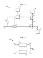
- Figure 1 shows an embodiment of a flow control device 1.
- Fluid such as a liquid, slurry, gas, and/or mixture thereof, enters the device 1 via a fluid inlet 9.
- a fluid flow control valve 2 adjusts the flow rate of fluid exiting the device 1 via a fluid outlet 7.
- the fluid flow control valve 2 is a pneumatically actuated valve that adjusts the flow rate of the fluid according to an amount of pneumatic pressure supplied to the pneumatic port of the fluid flow control valve 2.
- the device 1 also includes a flow meter 3, a controller 4, and a pneumatic pressure controlling portion 5 supplying controlled pneumatic pressure to the flow control valve 2 via a line 8.
- Flow meter 3 measures the flow rate of fluid flowing from the inlet 9 to the outlet 7 and communicates with the controller 4 to supply the controller 4 with an electronic signal indicative of the measured flow rate.
- the controller 4 in turn communicates with the pneumatic pressure controlling portion 5 to electronically control the pneumatic pressure controlling portion 5 and thereby adjust the amount of pneumatic pressure supplied to the flow control valve 2.
- the flow control valve 2 may be configured to increase and/or decrease the flow rate of the fluid in an amount related (e.g., proportional) to an increase and/or decrease of the amount of pneumatic pressure supplied to the valve 2.
- the fluid flow control valve 2 may also be configured to substantially maintain a liquid flow rate in an amount related (e.g., proportional) to a substantially maintained pneumatic pressure supplied to the valve 2.
- the use of a pneumatically actuated valve may optionally enable more rapid, accurate, and compliant valve controlling response. Further, the use of a pneumatically actuated valve may enable the valve 2 to better track a control signal.
- the flow control valve 2 may be a pneumatically controlled valve manufactured by Asahi.
- the controller 4 may be configured to act in response to sensed fluid pressure upstream from the valve 2 and to adjust the pneumatic pressure supplied to valve 2 to compensate for upstream pressure fluctuations.
- Other types of valves may also be used.
- Flow meter 3 may be any type of device capable of being used to measure flow rate of a fluid.
- the flow meter 3 may have a relatively high degree of accuracy.
- the flow meter 3 may be an ultrasonic flow meter.
- One exemplary flow meter is an ultrasonic flow meter manufactured by Tokyo Flow Meter.
- the flow meter 3 may be positioned to measure the fluid flow rate upstream of fluid flow control valve 2, as shown in Figure 1. Alternatively, the flow meter may be positioned to measure the fluid flow rate downstream of valve 2.
- the amount of pneumatic pressure supplied to the flow control valve 2 via line 8 may be controlled by pneumatic pressure controlling portion 5.
- the pressure controlling portion 5 may be configured to receive pressurized gas (e.g., a pressurized inert gas such as nitrogen or pressurized air) from a pressurized gas source 12 and then output the gas to line 8 at a pressure controlled according to an electronic signal supplied by the controller 4.
- the pressure controlling portion 5 could include one or more valves and/or pressure regulators.
- the pressure controlling portion 5 may be a proportional pneumatic pressure control valve.
- One exemplary valve may include one valving arrangement for outputting some of the input gas via line 8 and another valving arrangement for bleeding some of the input gas from the valve.
- the pressure controlling portion 5 may be able to provide output pressures in a range of pressures that are within the range of pressures that may be used to control the flow control valve 2.
- the pressure controlling portion 5 may be configured to provide output pressures in a range of 0 to about 50 PSI or any other range.
- the pneumatic pressure controlling portion 5 may be configured to sense pneumatic pressure in the line 8 and to adjust the pneumatic pressure control to compensate for pressure fluctuations in line 8.
- the pressure controlling portion 5 may have its own subcontroller controlling the pneumatic pressure controlling portion 5 at least according to the measured downstream pneumatic pressure.
- Such an exemplary arrangement may have a control loop associated with the subcontroller, which may be in addition to a possible control loop associated with the controller 4.
- the device 1 may include an optional pressure sensor 6 configured to measure pressure of the fluid and communicate with controller 4 to supply a signal indicative of the measured fluid pressure.
- the pressure sensor 6 may be positioned to sense pressure of the fluid upstream of the flow control valve 2, as shown in Figure 1. Such an arrangement may possibly improve output fluid flow rate stability when the supply of fluid to the device 1 has a varying pressure.
- pressure sensor 6 may be positioned to sense fluid pressure downstream of valve 2.
- the device 1 may also include an input portion 10 configured to enable input into the controller 4 of a desired fluid flow rate.
- the input portion 10 may include a keypad, a connection to a computer, a local or remote device, or any other configuration enabling a user to input a desired fluid flow rate.
- the input portion 10 may include a memory that stores one or more desired fluid flow rates and/or a separate processor that may determine a fluid flow rate.
- the controller 4 receives electronic signals from the flow meter 3, the pressure sensor 6, and the input portion 10. Based on one or more of those signals, the controller 4 may determine an appropriate signal to send to the pressure controlling portion 5 so as to cause a particular pneumatic pressure in line 8 and thereby cause a particular fluid flow rate via flow control valve 2.
- the controller 4 may vary the signal output to the pressure controlling portion 5 according to any changes in the input signals from the flow meter 3, the pressure sensor 6, and the input portion 10.
- pressure in the line 8 may be altered to either maintain a substantially steady state flow rate from the device 1 (e.g., when pressure of liquid flowing into the device 1 varies) and/or change the fluid flow rate from the device 1 (e.g., in response to a varied input from input portion 10).
- the controller 4 may be a PLC, an embedded or single board controller, or any other computing device, such as a PC.
- the controller 4 may use control logic or an algorithm to analyze the flow rate and optionally the influent pressure signal from sensor 6.
- the controller 4 may also determine a difference between the desired flow rate and the measured flow rate and generate an adjustment signal, which may be sent to controlling portion 5.
- This algorithm may be designed to compensate for specific behaviours of controlling portion 5 and fluid flow control valve 2.
- Such compensation may include: i) anticipation of mechanical valve actuation delays; ii) biasing of the control signal to increase valve opening or closing rates to closely track rapid changes in flow, pressure, or demanded flow rate; and/or iii) inverse biasing of the control signal to damp out ringing and/or overshoot of valve response. These compensations may be designed for specific hardware combinations.
- flow meter 3 and fluid flow control valve 2 may be selected for specific flow rate ranges.
- the algorithm and controlling portion 5 may allow for a high turn-down ratio for flow rate, while providing high accuracy across the entire flow rate range.
- Turn-down refers to the ability to operate at a value lower than the full-scale value of the device; for example, a high turn-down ratio flow controller may possibly operate accurately at both relatively low flows and high flows, without changing hardware.
- the control algorithm may compensate for specific valve characteristics by anticipating valve response to control signals and biasing the control signals to correct such valve response. This compensation may produce higher compliance for valve 2, better tracking between valve position and desired flow rate, and a more repeatable and stable flow rate.
- controller 4 may use a proportional-integral-derivative ("PID") feedback control method to adjust electronic control signal and/or pneumatic pressure in line 8.
- PID proportional-integral-derivative
- the controller 4 may calculate an error, which is based on the difference between the measured flow rate and the desired flow rate.
- error is broadly defined as the difference between the measured flow rate and the desired flow rate.
- the "proportional” term would refer to this error (or difference in flow rates)
- the "integral” term would refer to the sum of errors over a period of time
- the "derivative” term would refer to the rate of change of the errors over a period of time.
- the electronic control signal from controller 4 may vary as a function of the "proportional,” “integral,” and/or “derivative” terms of a PID loop; again, these terms vary based on the difference between the desired flow rate and the measured flow rate.
- the algorithm may also use both feed-forward (anticipating the correct fluid flow control valve 2 position) and feedback (measuring the flow rate after an adjustment is made) control methods. Using both control methods may provide for better performance. Alternatively, either one of the following two methods may be used alone in controlling flow.
- the first method may be a non-linear implementation of the integral term of the PID feedback control method.
- an algorithm may use the history of the error to compute the controller 4 output, which may then actuate the fluid flow control valve 2 (or control the pneumatic pressure controlling portion 5).
- the controller 4 may use the desired flow, the current flow, and the current pneumatic pressure setting to increment or decrement the pneumatic pressure based on the error. If, for example, this pressure change does not result in zero error, the controller 4 may iteratively apply the method again during the next scan. Additionally, the controller 4 may divide the possible error into several bands and apply a different pressure correction factor depending on the band. In examples using varying pressure correction factors, the controller 4 may actuate the fluid flow control valve 2 (or control the pneumatic pressure controlling portion 5) according to the selected band.
- the second method may be a feed-forward feedback control method.
- feed-forward an additional input is added to the system that is based on knowledge of an event that may cause an error to develop.
- a good example of a feed-forward control system is a water heater control loop.
- the PID or other feedback-based controller
- the water flow rate is monitored and the output to the heater is adjusted in response to a change in the flow rate in anticipation of the error that would develop.
- the system may respond more quickly to changes in flow.
- the controller 4 may use the requested flow rate change to compute and anticipate the expected pneumatic pressure setting for fluid flow control valve 2.
- the expected (or anticipated) pneumatic pressure setting may be calculated from an equation that is derived from a calibration procedure performed on 1, 2, 3, or any number of flow points.
- a second order differential equation may be fit to the flow points and controller 4 may use the equation to calculate the pneumatic pressure with some accuracy.
- a higher or lower order equation may also be used depending on the desired accuracy.
- the controller 4 may adjust the pneumatic pressure to this anticipated pressure while also using an integral or other method for the control loop.
- the controlled flow rate passing from the device 1 via the outlet 7 may be conveyed to another component 30 that may use the fluid.
- the component 30 may be a semiconductor manufacturing tool and the device 1 and tool might be parts of a system for use in semiconductor manufacturing.
- semiconductor manufacturing tools include load locks, wafer polishing tools, wafer etching tools, and any other type of device used in the manufacture of a semiconductor.
- Figure 2 schematically illustrates an embodiment of a system including a first flow control device 19 and a second flow control device 22, wherein each of the devices 19 and 22 may be configured identical to the fluid flow control device 1 previously described.
- a first fluid enters first flow control device 19 via fluid inlet 18, and exits device 19 via fluid outlet 20.
- a second fluid enters second flow control device 22 via fluid inlet 21, and exits device 22 via fluid outlet 23.
- the outlets 20 and 23 may be flow coupled together so as to create a blended fluid combination that may be passed from the system 16 via a line 24.
Landscapes
- Engineering & Computer Science (AREA)
- Physics & Mathematics (AREA)
- General Physics & Mathematics (AREA)
- Automation & Control Theory (AREA)
- Power Engineering (AREA)
- Flow Control (AREA)
- Measuring Volume Flow (AREA)
Applications Claiming Priority (4)
| Application Number | Priority Date | Filing Date | Title |
|---|---|---|---|
| US25438 | 1987-03-13 | ||
| US53459004P | 2004-01-06 | 2004-01-06 | |
| US534590P | 2004-01-06 | ||
| US11/025,438 US20050150552A1 (en) | 2004-01-06 | 2004-12-29 | Device, method, and system for controlling fluid flow |
Publications (2)
| Publication Number | Publication Date |
|---|---|
| EP1553474A2 true EP1553474A2 (de) | 2005-07-13 |
| EP1553474A3 EP1553474A3 (de) | 2005-11-23 |
Family
ID=34594132
Family Applications (1)
| Application Number | Title | Priority Date | Filing Date |
|---|---|---|---|
| EP20050250013 Withdrawn EP1553474A3 (de) | 2004-01-06 | 2005-01-05 | Vorrichtung und Verfahren zum Steuern eines Materialstroms unter der Verwendung eines pneumatisch betriebenen Ventils. |
Country Status (6)
| Country | Link |
|---|---|
| US (1) | US20050150552A1 (de) |
| EP (1) | EP1553474A3 (de) |
| JP (1) | JP2005196788A (de) |
| KR (1) | KR20050072683A (de) |
| CN (1) | CN1683817A (de) |
| SG (1) | SG113042A1 (de) |
Cited By (3)
| Publication number | Priority date | Publication date | Assignee | Title |
|---|---|---|---|---|
| WO2009153219A3 (en) * | 2008-06-20 | 2012-02-02 | L'air Liquide Societe Anonyme Pour L'etude Et L'exploitation Des Procedes Georges Claude | Apparatus and method for feeding a process medium |
| CN103616155A (zh) * | 2013-11-29 | 2014-03-05 | 中国人民解放军国防科学技术大学 | 超声速流场的流动控制装置 |
| CN108027619A (zh) * | 2015-09-11 | 2018-05-11 | 日立金属株式会社 | 质量流量控制装置 |
Families Citing this family (39)
| Publication number | Priority date | Publication date | Assignee | Title |
|---|---|---|---|---|
| US7389787B2 (en) * | 1998-12-21 | 2008-06-24 | Baker Hughes Incorporated | Closed loop additive injection and monitoring system for oilfield operations |
| US7690395B2 (en) | 2004-01-12 | 2010-04-06 | Masco Corporation Of Indiana | Multi-mode hands free automatic faucet |
| US7867172B1 (en) | 2006-11-09 | 2011-01-11 | Dingane Baruti | Combination toothbrush and peak flow meter system |
| US8438672B2 (en) | 2005-11-11 | 2013-05-14 | Masco Corporation Of Indiana | Integrated electronic shower system |
| US9243756B2 (en) | 2006-04-20 | 2016-01-26 | Delta Faucet Company | Capacitive user interface for a faucet and method of forming |
| US8365767B2 (en) | 2006-04-20 | 2013-02-05 | Masco Corporation Of Indiana | User interface for a faucet |
| US8118240B2 (en) | 2006-04-20 | 2012-02-21 | Masco Corporation Of Indiana | Pull-out wand |
| US8162236B2 (en) | 2006-04-20 | 2012-04-24 | Masco Corporation Of Indiana | Electronic user interface for electronic mixing of water for residential faucets |
| US8089473B2 (en) | 2006-04-20 | 2012-01-03 | Masco Corporation Of Indiana | Touch sensor |
| US9243392B2 (en) | 2006-12-19 | 2016-01-26 | Delta Faucet Company | Resistive coupling for an automatic faucet |
| CA2676976C (en) | 2007-01-31 | 2015-10-06 | Masco Corporation Of Indiana | Capacitive sensing apparatus and method for faucets |
| US7806141B2 (en) | 2007-01-31 | 2010-10-05 | Masco Corporation Of Indiana | Mixing valve including a molded waterway assembly |
| RU2339913C1 (ru) * | 2007-02-08 | 2008-11-27 | ОАО "Техприбор" | Система измерения массового расхода компонентов газожидкостного потока |
| US8376313B2 (en) | 2007-03-28 | 2013-02-19 | Masco Corporation Of Indiana | Capacitive touch sensor |
| EP2235272A1 (de) | 2007-12-11 | 2010-10-06 | Masco Corporation Of Indiana | Kapazitive kopplungsanordnung für eine armatur |
| KR100983889B1 (ko) * | 2008-04-14 | 2010-09-27 | 주식회사 조인솔루션 | 반도체 제조설비의 유틸리티 유량제어장치 |
| KR100968383B1 (ko) * | 2008-04-14 | 2010-07-07 | 주식회사 조인솔루션 | 반도체 제조설비의 유틸리티 유량제어장치 |
| KR100871079B1 (ko) * | 2008-04-14 | 2008-11-28 | 주식회사 조인솔루션 | 반도체 제조설비의 유틸리티 유량제어장치 |
| US8863833B2 (en) * | 2008-06-03 | 2014-10-21 | Baker Hughes Incorporated | Multi-point injection system for oilfield operations |
| PL3812870T5 (pl) | 2008-06-26 | 2026-04-13 | Belparts Group N.V. | System sterowania przepływem |
| JP5515474B2 (ja) * | 2009-07-14 | 2014-06-11 | 株式会社ジェイテクト | ステージ装置 |
| US8776817B2 (en) | 2010-04-20 | 2014-07-15 | Masco Corporation Of Indiana | Electronic faucet with a capacitive sensing system and a method therefor |
| US8561626B2 (en) | 2010-04-20 | 2013-10-22 | Masco Corporation Of Indiana | Capacitive sensing system and method for operating a faucet |
| GB201119284D0 (en) * | 2011-11-08 | 2011-12-21 | Isis Innovation | Pressure regulator |
| CN102437045A (zh) * | 2011-11-29 | 2012-05-02 | 上海宏力半导体制造有限公司 | 湿法刻蚀方法以及湿法刻蚀设备 |
| CN102538002B (zh) * | 2012-02-09 | 2016-12-14 | 北京百恒达石油技术有限公司 | 气动控制装置 |
| CN104254653B (zh) | 2012-04-20 | 2016-04-20 | 德尔塔阀门公司 | 包含电容感应式可拉出棒的水龙头 |
| WO2014143922A1 (en) * | 2013-03-15 | 2014-09-18 | Schneider Electric Buildings, Llc | Advanced valve actuator with true flow feedback |
| CN104712902B (zh) * | 2013-12-12 | 2017-02-08 | 中国科学院大连化学物理研究所 | 一种气体恒流量输出的前馈控制装置和方法 |
| DE112014006529B4 (de) * | 2014-03-28 | 2020-07-02 | Mitsubishi Electric Corporation | Drahtelektro-Entladungsmaschine |
| CN104696706B (zh) * | 2015-01-20 | 2017-08-04 | 哈尔滨工业大学 | 基于气压驱动的微流体流量调节装置 |
| US20170314475A1 (en) * | 2015-07-17 | 2017-11-02 | Power Driven Diesel, LLC | Remote pneumatic aneroid fuel controller devices and methods |
| NL2015613B1 (en) * | 2015-10-14 | 2017-05-08 | Fluidor Equipment B V | Method and system for clearing a pipe system. |
| CN105674060B (zh) * | 2016-01-01 | 2018-01-09 | 深圳德尔科机电环保科技有限公司 | 一种压缩空气系统压力流量联合控制节能装置及方法 |
| KR101977385B1 (ko) * | 2017-07-25 | 2019-05-13 | 무진전자 주식회사 | 웨이퍼 건조 장치 및 방법 |
| CN111089091B (zh) * | 2019-12-05 | 2022-06-24 | 上海航天控制技术研究所 | 一种微流量控制器及方法 |
| CN111288301B (zh) * | 2020-03-03 | 2021-11-09 | 领胜城科技(江苏)有限公司 | 一种利用电磁感应原理的可调控管道测量控制装置 |
| EP3882737B1 (de) * | 2020-03-20 | 2022-04-27 | Siemens Aktiengesellschaft | Fluiddrucksteuervorrichtung |
| CN114487078A (zh) * | 2021-12-30 | 2022-05-13 | 天津津普利环保科技股份有限公司 | 一种用于便携式fid检测器的进气稳流装置 |
Citations (1)
| Publication number | Priority date | Publication date | Assignee | Title |
|---|---|---|---|---|
| US6178996B1 (en) | 1998-12-28 | 2001-01-30 | Mks Japan, Inc. | Flow rate control apparatus |
Family Cites Families (16)
| Publication number | Priority date | Publication date | Assignee | Title |
|---|---|---|---|---|
| US3941148A (en) * | 1975-04-17 | 1976-03-02 | Sun Oil Company Of Pennsylvania | Control valve drive |
| US4534376A (en) * | 1983-09-01 | 1985-08-13 | Rosemount Inc. | Electric signal to pressure signal transducer |
| DD219605A1 (de) * | 1983-11-24 | 1985-03-06 | Tech Hochschule | Anordnung zur erzeugung eines nichtlinearen reglerverhaltens |
| DE3633852A1 (de) * | 1986-10-04 | 1988-04-07 | Bopp & Reuther Gmbh | Verfahren zum regeln von durchflussabhaengigen regelgroessen |
| US5197328A (en) * | 1988-08-25 | 1993-03-30 | Fisher Controls International, Inc. | Diagnostic apparatus and method for fluid control valves |
| US5047965A (en) * | 1989-01-05 | 1991-09-10 | Zlokovitz Robert J | Microprocessor controlled gas pressure regulator |
| JPH03156509A (ja) * | 1989-11-14 | 1991-07-04 | Stec Kk | マスフローコントローラ |
| US5251148A (en) * | 1990-06-01 | 1993-10-05 | Valtek, Inc. | Integrated process control valve |
| US5285715A (en) * | 1992-08-06 | 1994-02-15 | Hr Textron, Inc. | Electrohydraulic servovalve with flow gain compensation |
| US5549137A (en) * | 1993-08-25 | 1996-08-27 | Rosemount Inc. | Valve positioner with pressure feedback, dynamic correction and diagnostics |
| DE4431463C2 (de) * | 1994-09-03 | 1997-10-16 | Honeywell Ag | Kompaktregler für ein Regelventil |
| US5803107A (en) * | 1996-03-29 | 1998-09-08 | Lam Research Corporation | Method and apparatus for pressure control in vacuum processors |
| US5950668A (en) * | 1996-10-09 | 1999-09-14 | Fisher Controls International, Inc. | Control valve positioners having improved operating characteristics |
| US6056008A (en) * | 1997-09-22 | 2000-05-02 | Fisher Controls International, Inc. | Intelligent pressure regulator |
| US6766260B2 (en) * | 2002-01-04 | 2004-07-20 | Mks Instruments, Inc. | Mass flow ratio system and method |
| US7073392B2 (en) * | 2002-07-19 | 2006-07-11 | Celerity, Inc. | Methods and apparatus for pressure compensation in a mass flow controller |
-
2004
- 2004-12-29 US US11/025,438 patent/US20050150552A1/en not_active Abandoned
-
2005
- 2005-01-05 KR KR1020050000920A patent/KR20050072683A/ko not_active Withdrawn
- 2005-01-05 EP EP20050250013 patent/EP1553474A3/de not_active Withdrawn
- 2005-01-06 CN CNA2005100542129A patent/CN1683817A/zh active Pending
- 2005-01-06 SG SG200500208A patent/SG113042A1/en unknown
- 2005-01-06 JP JP2005001313A patent/JP2005196788A/ja active Pending
Patent Citations (1)
| Publication number | Priority date | Publication date | Assignee | Title |
|---|---|---|---|---|
| US6178996B1 (en) | 1998-12-28 | 2001-01-30 | Mks Japan, Inc. | Flow rate control apparatus |
Cited By (5)
| Publication number | Priority date | Publication date | Assignee | Title |
|---|---|---|---|---|
| WO2009153219A3 (en) * | 2008-06-20 | 2012-02-02 | L'air Liquide Societe Anonyme Pour L'etude Et L'exploitation Des Procedes Georges Claude | Apparatus and method for feeding a process medium |
| CN103616155A (zh) * | 2013-11-29 | 2014-03-05 | 中国人民解放军国防科学技术大学 | 超声速流场的流动控制装置 |
| CN103616155B (zh) * | 2013-11-29 | 2016-02-17 | 中国人民解放军国防科学技术大学 | 超声速流场的流动控制装置 |
| CN108027619A (zh) * | 2015-09-11 | 2018-05-11 | 日立金属株式会社 | 质量流量控制装置 |
| CN108027619B (zh) * | 2015-09-11 | 2021-03-09 | 日立金属株式会社 | 质量流量控制装置 |
Also Published As
| Publication number | Publication date |
|---|---|
| CN1683817A (zh) | 2005-10-19 |
| KR20050072683A (ko) | 2005-07-12 |
| US20050150552A1 (en) | 2005-07-14 |
| JP2005196788A (ja) | 2005-07-21 |
| SG113042A1 (en) | 2005-07-28 |
| EP1553474A3 (de) | 2005-11-23 |
Similar Documents
| Publication | Publication Date | Title |
|---|---|---|
| US20050150552A1 (en) | Device, method, and system for controlling fluid flow | |
| JP6193679B2 (ja) | ガス分流供給装置及びガス分流供給方法 | |
| US20230004176A1 (en) | Systems and methods for calibrating and tuning a mass flow controller | |
| US8240324B2 (en) | Method and apparatus for in situ testing of gas flow controllers | |
| US7143774B2 (en) | Method and apparatus for providing a determined ratio of process fluids | |
| US6631334B2 (en) | Pressure-based mass flow controller system | |
| JP6093019B2 (ja) | 質量流量制御システム | |
| US7918238B2 (en) | Flow controller and its regulation method | |
| US6138708A (en) | Mass flow controller having automatic pressure compensator | |
| US20120174990A1 (en) | Flow rate ratio controlling apparatus | |
| US20150121988A1 (en) | System and method for using a rate of decay measurement for real time measurement and correction of zero offset and zero drift of a mass flow controller or mass flow meter | |
| CN109416275A (zh) | 流量控制设备、流量控制设备的流量校正方法、流量测定设备及使用流量测定设备的流量测定方法 | |
| US10838437B2 (en) | Apparatus for splitting flow of process gas and method of operating same | |
| IL166167A (en) | Device, method, and system for controlling fluid flow | |
| JP2019105338A (ja) | 流体制御装置及び流体制御装置用プログラム | |
| JP7393143B2 (ja) | 液処理装置および流量検出部の校正方法 | |
| TW200523532A (en) | Device, method, and system for controlling fluid flow | |
| TW202613502A (zh) | 流量測定裝置及流體控制裝置 | |
| KR20180050610A (ko) | 유량제어시스템 | |
| KR20070031445A (ko) | 유동 측정 그리고 질량 유동 제어기의 검증을 위한 방법 및시스템 | |
| WO2013134144A1 (en) | System and method for providing a self validating mass flow controller or a mass flow meter utilizing a software protocol |
Legal Events
| Date | Code | Title | Description |
|---|---|---|---|
| PUAI | Public reference made under article 153(3) epc to a published international application that has entered the european phase |
Free format text: ORIGINAL CODE: 0009012 |
|
| AK | Designated contracting states |
Kind code of ref document: A2 Designated state(s): AT BE BG CH CY CZ DE DK EE ES FI FR GB GR HU IE IS IT LI LT LU MC NL PL PT RO SE SI SK TR |
|
| AX | Request for extension of the european patent |
Extension state: AL BA HR LV MK YU |
|
| PUAL | Search report despatched |
Free format text: ORIGINAL CODE: 0009013 |
|
| AK | Designated contracting states |
Kind code of ref document: A3 Designated state(s): AT BE BG CH CY CZ DE DK EE ES FI FR GB GR HU IE IS IT LI LT LU MC NL PL PT RO SE SI SK TR |
|
| AX | Request for extension of the european patent |
Extension state: AL BA HR LV MK YU |
|
| 17P | Request for examination filed |
Effective date: 20060411 |
|
| AKX | Designation fees paid |
Designated state(s): AT BE BG CH CY CZ DE DK EE ES FI FR GB GR HU IE IS IT LI LT LU MC NL PL PT RO SE SI SK TR |
|
| RAP1 | Party data changed (applicant data changed or rights of an application transferred) |
Owner name: BOC EDWARDS, INC. |
|
| RAP1 | Party data changed (applicant data changed or rights of an application transferred) |
Owner name: EDWARDS VACUUM, INC. |
|
| 17Q | First examination report despatched |
Effective date: 20071116 |
|
| RAP1 | Party data changed (applicant data changed or rights of an application transferred) |
Owner name: AIR LIQUIDE ELECTRONICS U.S. LP |
|
| STAA | Information on the status of an ep patent application or granted ep patent |
Free format text: STATUS: THE APPLICATION HAS BEEN WITHDRAWN |
|
| 18W | Application withdrawn |
Effective date: 20090608 |