EP1553674A2 - Unterputzdose - Google Patents
Unterputzdose Download PDFInfo
- Publication number
- EP1553674A2 EP1553674A2 EP04029539A EP04029539A EP1553674A2 EP 1553674 A2 EP1553674 A2 EP 1553674A2 EP 04029539 A EP04029539 A EP 04029539A EP 04029539 A EP04029539 A EP 04029539A EP 1553674 A2 EP1553674 A2 EP 1553674A2
- Authority
- EP
- European Patent Office
- Prior art keywords
- flush
- cavity
- mounted box
- box according
- opening
- Prior art date
- Legal status (The legal status is an assumption and is not a legal conclusion. Google has not performed a legal analysis and makes no representation as to the accuracy of the status listed.)
- Withdrawn
Links
Images
Classifications
-
- H—ELECTRICITY
- H02—GENERATION; CONVERSION OR DISTRIBUTION OF ELECTRIC POWER
- H02G—INSTALLATION OF ELECTRIC CABLES OR LINES, OR OF COMBINED OPTICAL AND ELECTRIC CABLES OR LINES
- H02G3/00—Installations of electric cables or lines or protective tubing therefor in or on buildings, equivalent structures or vehicles
- H02G3/02—Details
- H02G3/08—Distribution boxes; Connection or junction boxes
- H02G3/12—Distribution boxes; Connection or junction boxes for flush mounting
- H02G3/121—Distribution boxes; Connection or junction boxes for flush mounting in plain walls
Definitions
- the present invention relates to a device according to the The preamble of claim 1, i. a flush-mounted box for electrical installation, with one accessible from the front Cavity in which from the side or from behind under plaster laid electrical lines are feasible.
- flush boxes for example, but not exclusively for the installation of electrical equipment such as For example, for the installation of switches, sockets, Telephone jacks, antenna jacks etc., or for the connection of electrical consumers such as lamps, Fans etc. to the mains, or as access to under Plaster laid and used electrical wiring often also as junction boxes, junction boxes, cable sockets, Switch boxes, junction boxes, accessory boxes, wall outlet boxes, Lighting outlet boxes etc. referred.
- flush-mounted box also referred to as flush-mounted boxes Devices are to be understood.
- a flush box of the aforementioned type is for example the device junction box with the article number 1555-02 Kaiser GmbH & Co. KG, Ramsloh 4, D-58579 Schalksmühle.
- the present invention is therefore based on the object the flush-mounted box according to the preamble of patent claim 1 in such a way that about the flush box less Cold and air can get inside the building as it has so far the case is.
- the flush-mounted box according to the invention is characterized that next to and / or behind the cavity, a second cavity is provided, which is arranged and dimensioned, in that the electrical leads to be led into the first cavity at least partially over the second cavity in the first cavity are feasible
- flush-mounted box described below is for assembly designed in a roller shutter box.
- the use of flush-mounted boxes is not on the installation limited in shutter boxes.
- the here presented flush box can be installed in "normal" walls, where it at flush-mounted boxes intended for installation in normal walls can prove beneficial, the shape, the size and the structure of the flush box to the changed conditions adapt.
- the flush box 1 consists in the example considered Plastic and is produced by injection molding. hereupon however, there is no restriction.
- the flush box could also be made in any other way and also from any other material getting produced.
- the flush-mounted box is made of two identically constructed halves 1a and 1b assembled. One of these halves, more precisely the half 1a is shown in FIG.
- the two halves 1a, 1b have locking lugs 15 and locking recesses or Detent openings 16 formed locking elements, which during assembly the two halves snap into each other and the holding both halves together.
- the flush box 1 has a cylindrical shape with different Diameters up. More precisely, it is that the flush box a front section 11 and a rear Section 12, wherein the front portion 11 that section of the flush box that is in the Roller shutter box built-in condition outside the roller shutter box comes to rest, and wherein the front section 11 has a larger diameter than the rear portion 12th
- the outer diameter of the rear portion 12 is in considered example about 5 cm, and the outer diameter of the front section 11 about 6 cm. However, insists on this no restriction.
- the mentioned diameters can be independent be of any size.
- the diameter of the front portion 11 and the rear portion 12 can also be the same size, and it could also be the rear Section 12 have the larger diameter.
- the flush box 1 is as illustrated in FIG is, in a roller shutter box 2, more precisely in one provided opening 21 is used.
- the direction in which the flush box 1 must be moved to enter the opening 21st to be used, is hereinafter referred to as plug-in direction designated.
- plug-in direction As used in the opening 21 Condition of the flush box is the rear section 12th lie in the opening 21, and beats the front section 11 from the outside to the roller shutter box 2.
- the length the rear portion 12 is preferably dimensioned such that this is not in the roller shutter box 2 cavity 22 protrudes, in which, inter alia, the (in the figure not shown) shutters and a shaft 23 to which of the Rolling shutters is wound.
- the length of the front section 11 preferably corresponds approximately to the thickness of the plaster layer, the on the roller shutter box and containing them Wall is applied.
- the diameter of the front portion 11 corresponds approximately the diameter of conventional cylindrical flush-mounted boxes. This makes it possible for conventional flush-mounted boxes manufactured accessories such as lids for Closing the front open flush boxes also for the here presented flush box to use.
- the diameter of the rear portion 12 corresponds approximately the inner diameter of the opening 21.
- the opening 21 is in general a prefabricated opening in the roller shutter box.
- the commercially available roller shutter boxes have on their Front mostly already two such openings. From These openings are used to make an opening Belt guide device to mount over which the Pulling up and lowering the roller shutter belt in the cavity 22 of the shutter box, more precisely to a attached to the shaft 23 (not shown in the figure) Winding disk is guided. Two such openings are provided, because it is in the manufacture of the shutter box it is not known whether the roller shutter belt and thus the Belt guide device left or right of the window be provided over which the roller shutter box attached is.
- the two openings 21 in the roller shutter box 2 only an opening 21 for the installation of the belt guiding device needed.
- the other opening 21 has not been otherwise used and simply bricked up.
- the presented here Flush-mounted box allows this opening 21 for the Introduction of electrical wiring in the cavity 21 of the Roller shutter box 2 to use.
- the electrical wires can, for example, for the power supply of a later Built-in electric motor for pulling up and lowering be used for the shutter, or for the connection of am underlying windows burglary detection sensors.
- flush-mounted box presented here with a flush-mounted box, which also has particularly good thermal insulation properties and no or much less air exchange between the cavity 22 and the building interior permits than when using conventional flush-mounted boxes the case would be.
- the flush box has two successive cavities on, namely a front lying first cavity 13th and a second cavity 14 located behind.
- the first cavity 13 has a lateral boundary wall 131 and a bottom 132, and is open towards the front; the open front of the first cavity 13 is through an attachable or unscrewable in the figures, not shown Lid closable.
- the lateral boundary wall 131 has a plurality of Boundary wall breakable elements 1311 on. Breaking one One or more of these elements emerge in the Boundary wall 131 openings, which from outside the Flush-mounted socket 1 electrical wiring in the first cavity 13 can be performed.
- the bottom 132 has an opening 1321 over which the first cavity 13 with the second cavity 14 in connection stands.
- This opening 1321 has a double function: over this Opening 1321, the second cavity 14 with a heat-insulating Material to be filled, and over this opening can also electrical lines from the first cavity 13 in the second cavity 14 are guided. This will be later described in more detail.
- the second cavity 14 has a lateral boundary wall 141, a bottom 142 and one through the bottom 132 of the first Cavity 13 formed front boundary wall.
- the lateral boundary wall 141 points in the insertion direction extending slots 1411 on. More precisely, it is at a small mutual distance parallel to each other running pairs of slots 1411. It is already on this Point out that the slots are arbitrary can be arranged differently, and that instead of slots also differently shaped openings in the lateral boundary wall can be provided.
- a bridge 1412 stops which is on its outside is provided with projections 1413.
- projections 1413 become as can be seen in particular from Figure 1, in the considered Example through transverse to the insertion direction and with respect to the insertion direction arranged one behind the other Formed ribs.
- the ribs 1413 preferably have a flat rising rear flank and a steep slope or the respective rib undercutting front Flank up.
- the lateral flanks of the ribs 1413 run, as can be seen in particular from FIG. 3C, in parallel to the direction in which the two halves 1a, 1b, from which the flush box is assembled when assembling the halves must be moved towards each other.
- the ribs 1413 are of different heights, namely such that the at the front and rear ends of the webs 1412 provided ribs are lowest, and the ribs around so get higher the further they are in the middle of the webs.
- the ribs 1413 protrude from the lateral boundary wall 141 up, so that the maximum outer diameter of the rear Section 12 of the flush box by the height of the ribs 1413 is determined.
- the maximum outer diameter of the rear Section is preferably larger than the inner diameter the opening 21, in which the flush-mounted box used becomes.
- the outer diameter of the lateral boundary walls 131 and 141 (without the ribs 1413 is preferably somewhat none as the inner diameter of the opening 21.
- the ribs 1413 become wedged in the inserted state in the opening 21 with the opening 21 surrounding roller shutter box section, and act the ribs 1413 like barbs, which both pull out the flush box as well as turning the flush-mounted box about its longitudinal axis prevent. It should be clear and needs no one closer explanation that provided on the webs 1412 Projections 1413 not by the above-described Ribs must be formed. Like the described ribs Acting projections can also be realized in any other way be, for example, by tapering pins.
- the bottom 142 has an easy to penetrate vulnerability or a breakable element 1421. by Knocks or you pierce this vulnerability, or you break that breakable element out, arises in the bottom 142 a Opening, passed through which electrical lines can be.
- flush box 1 used to be installed, one on a building interior wall under plaster electrical line into the cavity 22 of the shutter box 2 to lead.
- the second cavity 14 with a heat-insulating Material filled As a thermally insulating material used in the example considered a curing foam, For example, a PU foam or a polyurethane foam.
- This Foam is passed through a tube or hose which which on the provided in the bottom 132 opening 1321 and on the projecting into the second cavity 14 spout in the second cavity is pushed, filled in the second cavity.
- the opening 1321 and the spout serve here as a foam filling opening.
- the foam fills the second cavity 14 and passes through the in the lateral boundary wall 141 provided slots 1411 also in the intermediate space between the flush box and the opening 21st bounding shutter box sections.
- the in this gap reaching foam provides additional attachment the flush box in the opening 21 and for a even better thermal insulation.
- the sealing lips 1414 and / or 1415 make sure that the foam does not spread uncontrollably can. If enough foam in the second cavity is filled, the pipe used for filling or the tube used for filling from the second cavity pulled out. The spout is designed so that over this no foam from the second cavity 14 in the first Can reach cavity 13.
- the channel is in the simplest case generated by means of a screwdriver, which over the in the soil 132 of the first cavity 13 provided opening 1321 in the passed second cavity 14 and then through the foam and the Bottom 142 of the second cavity 14 is pressed.
- the channel but could also be using a drill or a milling machine are generated.
- the diameter of the channel corresponds the diameter of the line to be led through this or is only slightly larger.
- the described Flush-mounted box can also be installed in a wall, that is not only suitable for installation in a roller shutter box.
- flush box If the described flush box is installed in a wall there is no need for these to have a front Large diameter section and a rear section having a smaller diameter. But you can, too a trained as described above flush box can be used as a flush-mounted box for a normal wall.
- the second Cavity 14 is disposed behind the first cavity 13. Of the second cavity could also be laterally adjacent to the first cavity be arranged, or the first cavity completely or partially circulate.
- the second Cavity 14 only after installation in this receiving Fill wall opening with heat-insulating material. It could also be provided that the second cavity already during the production of the same with heat-insulating Material is filled, for example, that during manufacture the flush box a thermally insulating body such as a polystyrene block, or a PU block, or a PUR block is inserted into the second cavity.
- a thermally insulating body such as a polystyrene block, or a PU block, or a PUR block is inserted into the second cavity.
- the electrical wiring is connected to the flush-mounted box arrive or depart from the flush-mounted box by in the Wall laid pipes run, can be provided that on those places where the relevant electrical Lines enter the second cavity or the second Leave the cavity from the outside of the flush-mounted box Go off spigots on which the pipes are attachable or in which the tubes are inserted.
- Flush-mounted boxes of the type described above are after all universally applicable flush-mounted boxes with excellent Thermal insulation and minimal air permeability.
Landscapes
- Engineering & Computer Science (AREA)
- Architecture (AREA)
- Civil Engineering (AREA)
- Structural Engineering (AREA)
- Connection Or Junction Boxes (AREA)
Abstract
Description
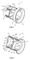
- Figur 1
- eine perspektivische Ansicht der im folgenden beschriebenen Unterputzdose,
- Figur 2
- eine perspektivische Ansicht einer der zwei identisch aufgebauten Hälften, aus welchen die Unterputzdose gemäß Figur 1 zusammengesetzt ist,
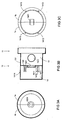
- Figur 3A
- eine Ansicht der in den Figuren 1 und 2 gezeigten Unterputzdose von oben,
- Figur 3B
- eine Seitenansicht der in der Figur 3A gezeigten Unterputzdose,
- Figur 3C
- eine Ansicht der in der Figur 3A gezeigten Unterputzdose von unten, und
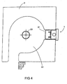
- Figur 4
- eine Seitenansicht einer in einen Rolladenkasten eingebauten Unterputzdose gemäß den Figuren 1 bis 3.
- daß die Unterputzdose 1 in die Öffnung 21 des Rolladenkastens 2 eingesetzt wird,
- daß die in den Hohlraum 22 zu führende Leitung so verlegt wird, daß sie über eine Öffnung, die durch ein Herausbrechen eines Elementes 1311 aus der Begrenzungswand 131 des ersten Hohlraumes 13 entsteht, in den ersten Hohlraum 13 geführt werden kann,
- daß der zweite Hohlraum 14 mit einem wärmedämmenden Material befüllt wird,
- daß ein das wärmedämmende Material und den Boden 142 (die Schwachstelle 1421 desselben) durchlaufender Kanal gebildet wird, über welchen die elektrische Leitung durch den zweiten Hohlraum 14 führbar ist, und
- daß die in den ersten Hohlraum 13 geführte Leitung über die im Boden 132 des ersten Hohlraumes 13 vorgesehene Öffnung 1321, die von dort in den zweiten Hohlraum 14 ragende Tülle, und den den zweiten Hohlraum 14 durchlaufenden Kanal in den Hohlraum 22 des Rolladenkastens 2 geführt wird. Zur Montage der Unterputzdose 1 wird diese in die Öffnung 21 des Rolladenkastens 2 gesteckt. Dabei kommen die hinteren Flanken der Rippen 1413 mit dem die Öffnung 21 umgebenden Rolladenkastenabschnitt in Berührung. Da der durch die Höhe der Rippen 1413 bestimmte maximale Außendurchmesser des hinteren Anschnittes 12 der Unterputzdose größer ist als der Innendurchmesser der Öffnung 21, werden die Rippen 1413 zusammen mit den diese tragenden Stegen 1412 in den zweiten Hohlraum 14 gedrückt. Dies ist möglich, weil die dünnen Stege 1412 relativ zum Rest der Unterputzdose 1 elastisch bewegbar sind. Insbesondere dann, wenn die Stege nicht oder nicht in dem erforderlichen Umfang bewegt werden können, kann alternativ oder zusätzlich vorgesehen werden, daß die Rippen 1413 elastisch zusammendrückbar ausgebildet sind. Das Wegdrücken der Rippen 1413 hat den positiven Effekt, daß die Unterputzdose weiter in die Öffnung 21 hineingeschoben werden kann. Das Hineinschieben der Unterputzdose 1 in die Öffnung 21 läßt sich mit einem verhältnismäßig geringen Kraftaufwand bewerkstelligen. Zwar drücken die Rippen 1413 gegen die die Öffnung 21 umgebenden Rolladenkastenabschnitte, doch sind die hinteren Flanken der Rippen relativ flach, so daß die Rippen an den die Öffnung 21 umgebenden Rolladenkastenabschnitten entlanggleiten können. Die Unterputzdose wird bis zum Anschlag des vorderen Abschnittes 11 der Unterputzdose am Rolladenkasten in die Öffnung 21 eingeschoben. Die dann von der Unterputzdose eingenommene Stellung ist in der Figur 4 gezeigt. Die Unterputzdose sitzt in diesem Zustand fest in der Öffnung 21 und muß nicht weiter befestigt werden. Die Unterputzdose kann ohne eine weitere Befestigung weder aus der Öffnung 21 herausgezogen werden noch um ihre Längsachse gedreht werden. Dies wird durch die für diese Art von Bewegung wie Widerhaken wirkenden Rippen 1413 verhindert.
- 1
- Unterputzdose
- 1a, 1b
- Hälften, aus welchen 1 zusammengesetzt ist
- 2
- Rolladenkasten
- 11
- vorderer Abschnitt von 1
- 12
- hinterer Abschnitt von 1
- 13
- erster Hohlraum
- 14
- zweiter Hohlraum
- 15
- Rastnase
- 16
- Rastöffnung
- 21
- Öffnung in 2
- 22
- Hohlraum in 2
- 23
- Welle
- 131
- seitliche Begrenzungswand von 13
- 132
- Boden von 13 und vordere Begrenzungswand von 14
- 141
- seitliche Begrenzungswand von 14
- 142
- Boden von 14
- 1311
- aus 131 herausbrechbares Element
- 1321
- Öffnung in 132
- 1411
- Schlitz
- 1412
- Steg
- 1413
- Rippen
- 1414
- Dichtlippe
- 1415
- Dichtlippe
- 1421
- Schwachstelle in 142 oder aus 142 herausbrechbares Element
Claims (16)
- Unterputzdose für die Elektroinstallation, mit einem von vorne zugänglichen Hohlraum, in welchen von der Seite oder von hinten unter Putz verlegte elektrische Leitungen hineinführbar sind,
dadurch gekennzeichnet, daß neben und/oder hinter dem Hohlraum ein zweiter Hohlraum vorgesehen ist, welcher derart angeordnet und bemessen ist, daß die in den ersten Hohlraum zu führenden elektrischen Leitungen zumindest teilweise über den zweiten Hohlraum in den ersten Hohlraum führbar sind. - Unterputzdose nach Anspruch 1,
dadurch gekennzeichnet, daß der erste Hohlraum über eine Öffnung mit dem zweiten Hohlraum verbunden ist, und daß die über den zweiten Hohlraum in den ersten Hohlraum geführten elektrischen Leitungen über diese Öffnung in den ersten Hohlraum geführt werden. - Unterputzdose nach Anspruch 2,
dadurch gekennzeichnet, daß die Öffnung ungefähr so groß ist wie die durch diese hindurchzuführenden elektrischen Leitungen. - Unterputzdose nach Anspruch 2,
dadurch gekennzeichnet, daß an der Öffnung eine Tülle angebracht ist, und daß die über den zweiten Hohlraum in den ersten Hohlraum geführten elektrischen Leitungen über diese Tülle in den ersten Hohlraum geführt werden. - Unterputzdose nach Anspruch 5,
dadurch gekennzeichnet, daß die Tülle die elektrischen Leitungen eng umschließt. - Unterputzdose nach Anspruch 1,
dadurch gekennzeichnet, daß der zweite Hohlraum mit wärmedämmendem Material gefüllt ist oder befüllbar ist. - Unterputzdose nach Anspruch 6 in Verbindung mit Anspruch 2,
dadurch gekennzeichnet, daß der zweite Hohlraum über die Öffnung mit wärmedämmendem Material befüllt wird, über welche der erste Hohlraum mit dem zweiten Hohlraum verbunden ist. - Unterputzdose nach Anspruch 7,
dadurch gekennzeichnet, daß als wärmedämmendes Material ein aushärtender Schaum verwendet wird. - Unterputzdose nach Anspruch 8,
dadurch gekennzeichnet, daß als wärmedämmendes Material ein PU-Schaum verwendet wird. - Unterputzdose nach Anspruch 8,
dadurch gekennzeichnet, daß als wärmedämmendes Material ein PUR-Schaum verwendet wird. - Unterputzdose nach Anspruch 8,
dadurch gekennzeichnet, daß der zweite Hohlraum in seinen seitlichen Begrenzungswänden Öffnungen aufweist, über welche der aushärtende Schaum in den Zwischenraum zwischen der Unterputzdose und die diese aufnehmende Wandöffnung gelangen kann. - Unterputzdose nach Anspruch 6,
dadurch gekennzeichnet, daß die elektrischen Leitungen durch im wärmedämmenden Material gebildete Kanäle geführt werden. - Unterputzdose nach Anspruch 12,
dadurch gekennzeichnet, daß der Durchmesser der wärmedämmenden Kanäle dem Durchmesser der durch sie geführten Leitungen entspricht. - Unterputzdose nach Anspruch 1,
dadurch gekennzeichnet, daß an der Außenseite der Unterputzdose Vorsprünge vorgesehen sind, die sich im in die Wandöffnung eingesetzten Zustand der Unterputzdose mit den die Wandöffnung umgebenden Wandabschnitten verkeilen. - Unterputzdose nach Anspruch 14,
dadurch gekennzeichnet, daß die Vorsprünge so ausgebildet, bemessen und angeordnet sind, daß sie ein Herausziehen der Unterputzdose aus der Wandöffnung erschweren oder verhindern. - Unterputzdose nach Anspruch 14,
dadurch gekennzeichnet, daß die Vorsprünge so ausgebildet, bemessen und angeordnet sind, daß sie ein Drehen der Unterputzdose innerhalb der Wandöffnung erschweren oder verhindern.
Applications Claiming Priority (2)
| Application Number | Priority Date | Filing Date | Title |
|---|---|---|---|
| DE2003159004 DE10359004A1 (de) | 2003-12-15 | 2003-12-15 | Unterputzdose |
| DE10359004 | 2003-12-15 |
Publications (2)
| Publication Number | Publication Date |
|---|---|
| EP1553674A2 true EP1553674A2 (de) | 2005-07-13 |
| EP1553674A3 EP1553674A3 (de) | 2009-04-15 |
Family
ID=34585309
Family Applications (1)
| Application Number | Title | Priority Date | Filing Date |
|---|---|---|---|
| EP04029539A Withdrawn EP1553674A3 (de) | 2003-12-15 | 2004-12-14 | Unterputzdose |
Country Status (2)
| Country | Link |
|---|---|
| EP (1) | EP1553674A3 (de) |
| DE (1) | DE10359004A1 (de) |
Cited By (2)
| Publication number | Priority date | Publication date | Assignee | Title |
|---|---|---|---|---|
| CH701113A1 (de) * | 2009-05-22 | 2010-11-30 | Robert Blaser | Geräteträger für Befestigungen an einer thermisch zu isolierenden Bauwerksoberfläche. |
| EP4009459A1 (de) * | 2020-12-04 | 2022-06-08 | Denis Bronsert | Hohlwandinstallationsdose |
Families Citing this family (2)
| Publication number | Priority date | Publication date | Assignee | Title |
|---|---|---|---|---|
| DE102018210360A1 (de) * | 2018-06-26 | 2020-01-02 | Adolf Würth Gmbh & Co Kg | Montagehilfe für eine Unterputzdose, Verfahren zum Montieren und Anordnung |
| DE202023106908U1 (de) * | 2023-11-22 | 2024-11-25 | F-Tronic Gmbh | Installationsdose für die Elektroinstallation |
Family Cites Families (5)
| Publication number | Priority date | Publication date | Assignee | Title |
|---|---|---|---|---|
| US3684819A (en) * | 1971-02-25 | 1972-08-15 | Ronald G Wilson | Sealing boot for an electrical receptacle |
| US4667840A (en) * | 1984-11-16 | 1987-05-26 | Lindsey Travis C | Fire-resistant electrical junction boxes and method of manufacture |
| FR2771224B1 (fr) * | 1997-11-20 | 2000-02-25 | Placoplatre Sa | Procede de montage d'une boite d'encastrement dans une cloison creuse et boitier pour la mise en oeuvre d'un tel procede |
| CA2227659A1 (en) * | 1998-01-21 | 1999-07-21 | Patrick O'donnell | Enclosure for interfacing electrical and control or communication devices |
| US6239365B1 (en) * | 1999-05-20 | 2001-05-29 | Mcevers Douglas W. | Sealable electrical outlet enclosure |
-
2003
- 2003-12-15 DE DE2003159004 patent/DE10359004A1/de not_active Ceased
-
2004
- 2004-12-14 EP EP04029539A patent/EP1553674A3/de not_active Withdrawn
Cited By (2)
| Publication number | Priority date | Publication date | Assignee | Title |
|---|---|---|---|---|
| CH701113A1 (de) * | 2009-05-22 | 2010-11-30 | Robert Blaser | Geräteträger für Befestigungen an einer thermisch zu isolierenden Bauwerksoberfläche. |
| EP4009459A1 (de) * | 2020-12-04 | 2022-06-08 | Denis Bronsert | Hohlwandinstallationsdose |
Also Published As
| Publication number | Publication date |
|---|---|
| EP1553674A3 (de) | 2009-04-15 |
| DE10359004A1 (de) | 2005-07-21 |
Similar Documents
| Publication | Publication Date | Title |
|---|---|---|
| AT520129A2 (de) | Lichttechnische Abdeckung für Langfeldleuchten | |
| DE102008015128A1 (de) | Dichthülle für ein Unterputz-Installationsgerät | |
| EP1553674A2 (de) | Unterputzdose | |
| EP2104821B1 (de) | Kältegerät | |
| BE1017293A6 (de) | Intumeszierende elektrische installationsteile. | |
| EP0957552B1 (de) | Gerätedose für Elektro-Installationsgeräte | |
| EP2643911A2 (de) | Einzelzugabdichtung | |
| WO1988004853A1 (fr) | Prise electrique pour jonctions de cables, notamment pour canalisations de cables | |
| EP3613116B1 (de) | Installationsvorrichtung mit einem dübel und einer darin eindrehbaren halterung für den einbau von unterputzgeräten | |
| DE3245384A1 (de) | Elektrische stromschiene zur stromversorgung sowie dazugehoerige anschlussvorrichtung | |
| DE69836574T2 (de) | Elektrischer Kasten | |
| EP3163699A1 (de) | Kabelkanalabschnitt, kabelkanal und kabelkanalsystem | |
| DE10161305A1 (de) | Leitungsdurchführung | |
| DE102012217815B4 (de) | Leitungskanal | |
| DE102004005189A1 (de) | Unterputzdose | |
| DE102008013640B4 (de) | Eckverbinder zum Verbinden von Hohlprofil-Rahmenteilen zur Abstandshalterung von Isolierglasscheiben sowie Isolierglasfenster | |
| DE102021107998A1 (de) | Dichtung mit wenigstens einem integrierten Leiter | |
| DE102018121693B4 (de) | Elektroinstallationsdose | |
| AT8416U1 (de) | Installationsdose für elektrotechnische zwecke | |
| DE202013012683U1 (de) | Hohlraumdose für die Elektroinstallation | |
| DE69701669T2 (de) | Kanal für elektrische Anlage und Verwendung | |
| DE19702122C1 (de) | Anschlußelement | |
| EP4417847A1 (de) | Wärmeübertrager-wanddurchführung, formteil und verwendung | |
| EP1638180A1 (de) | Haube zum Abdecken des Kopfes einer Isolationskerze | |
| EP1688579A2 (de) | Fenstersturz, Unterputzdose, und Führungsvorrichtung für ein Rolladensystem |
Legal Events
| Date | Code | Title | Description |
|---|---|---|---|
| PUAI | Public reference made under article 153(3) epc to a published international application that has entered the european phase |
Free format text: ORIGINAL CODE: 0009012 |
|
| AK | Designated contracting states |
Kind code of ref document: A2 Designated state(s): AT BE BG CH CY CZ DE DK EE ES FI FR GB GR HU IE IS IT LI LT LU MC NL PL PT RO SE SI SK TR |
|
| AX | Request for extension of the european patent |
Extension state: AL BA HR LV MK YU |
|
| PUAL | Search report despatched |
Free format text: ORIGINAL CODE: 0009013 |
|
| AK | Designated contracting states |
Kind code of ref document: A3 Designated state(s): AT BE BG CH CY CZ DE DK EE ES FI FR GB GR HU IE IS IT LI LT LU MC NL PL PT RO SE SI SK TR |
|
| AX | Request for extension of the european patent |
Extension state: AL BA HR LV MK YU |
|
| AKX | Designation fees paid | ||
| STAA | Information on the status of an ep patent application or granted ep patent |
Free format text: STATUS: THE APPLICATION IS DEEMED TO BE WITHDRAWN |
|
| 18D | Application deemed to be withdrawn |
Effective date: 20091013 |
|
| REG | Reference to a national code |
Ref country code: DE Ref legal event code: 8566 |