EP1553688B1 - Installation zum betrieben einer Tür eines Gebaüde und Verfahren zur Steuerung der elektrischen Versorgung einer solchen Installation. - Google Patents
Installation zum betrieben einer Tür eines Gebaüde und Verfahren zur Steuerung der elektrischen Versorgung einer solchen Installation. Download PDFInfo
- Publication number
- EP1553688B1 EP1553688B1 EP04029011A EP04029011A EP1553688B1 EP 1553688 B1 EP1553688 B1 EP 1553688B1 EP 04029011 A EP04029011 A EP 04029011A EP 04029011 A EP04029011 A EP 04029011A EP 1553688 B1 EP1553688 B1 EP 1553688B1
- Authority
- EP
- European Patent Office
- Prior art keywords
- voltage
- threshold
- control method
- switch
- rectified
- Prior art date
- Legal status (The legal status is an assumption and is not a legal conclusion. Google has not performed a legal analysis and makes no representation as to the accuracy of the status listed.)
- Expired - Lifetime
Links
- 238000000034 method Methods 0.000 title claims abstract description 30
- 238000009434 installation Methods 0.000 title claims abstract description 20
- 239000003990 capacitor Substances 0.000 claims abstract description 18
- 230000004048 modification Effects 0.000 claims description 2
- 238000012986 modification Methods 0.000 claims description 2
- 230000001960 triggered effect Effects 0.000 claims 6
- 230000000630 rising effect Effects 0.000 claims 3
- 230000001143 conditioned effect Effects 0.000 claims 1
- 238000012360 testing method Methods 0.000 description 8
- 239000003638 chemical reducing agent Substances 0.000 description 4
- 230000008901 benefit Effects 0.000 description 3
- 230000000903 blocking effect Effects 0.000 description 2
- 230000000295 complement effect Effects 0.000 description 2
- 230000006378 damage Effects 0.000 description 2
- 230000002427 irreversible effect Effects 0.000 description 2
- 238000004519 manufacturing process Methods 0.000 description 2
- 238000013021 overheating Methods 0.000 description 2
- 230000008569 process Effects 0.000 description 2
- 230000007704 transition Effects 0.000 description 2
- 230000004913 activation Effects 0.000 description 1
- 230000008859 change Effects 0.000 description 1
- 238000006243 chemical reaction Methods 0.000 description 1
- 230000007423 decrease Effects 0.000 description 1
- 230000007547 defect Effects 0.000 description 1
- 230000001419 dependent effect Effects 0.000 description 1
- 238000013461 design Methods 0.000 description 1
- 230000006866 deterioration Effects 0.000 description 1
- 238000010586 diagram Methods 0.000 description 1
- 238000005265 energy consumption Methods 0.000 description 1
- 230000006872 improvement Effects 0.000 description 1
- 230000007935 neutral effect Effects 0.000 description 1
- 230000009467 reduction Effects 0.000 description 1
- 230000003252 repetitive effect Effects 0.000 description 1
- 230000002441 reversible effect Effects 0.000 description 1
Images
Classifications
-
- H—ELECTRICITY
- H02—GENERATION; CONVERSION OR DISTRIBUTION OF ELECTRIC POWER
- H02M—APPARATUS FOR CONVERSION BETWEEN AC AND AC, BETWEEN AC AND DC, OR BETWEEN DC AND DC, AND FOR USE WITH MAINS OR SIMILAR POWER SUPPLY SYSTEMS; CONVERSION OF DC OR AC INPUT POWER INTO SURGE OUTPUT POWER; CONTROL OR REGULATION THEREOF
- H02M7/00—Conversion of AC power input into DC power output; Conversion of DC power input into AC power output
- H02M7/02—Conversion of AC power input into DC power output without possibility of reversal
- H02M7/04—Conversion of AC power input into DC power output without possibility of reversal by static converters
- H02M7/12—Conversion of AC power input into DC power output without possibility of reversal by static converters using discharge tubes with control electrode or semiconductor devices with control electrode
- H02M7/21—Conversion of AC power input into DC power output without possibility of reversal by static converters using discharge tubes with control electrode or semiconductor devices with control electrode using devices of a triode or transistor type requiring continuous application of a control signal
- H02M7/217—Conversion of AC power input into DC power output without possibility of reversal by static converters using discharge tubes with control electrode or semiconductor devices with control electrode using devices of a triode or transistor type requiring continuous application of a control signal using semiconductor devices only
- H02M7/2176—Conversion of AC power input into DC power output without possibility of reversal by static converters using discharge tubes with control electrode or semiconductor devices with control electrode using devices of a triode or transistor type requiring continuous application of a control signal using semiconductor devices only comprising a passive stage to generate a rectified sinusoidal voltage and a controlled switching element in series between such stage and the output
Definitions
- the invention relates to a feeding method defined by the preamble of claim 1. It also relates to an installation for carrying out this method.
- An actuator for operating a movable closure member generally comprises a DC motor, a gearbox and a kinematic connection between the output of the gearbox and the movable closure member.
- the electric power of the engine is of the order of one hundred watts.
- a geared motor assembly typically used to drive car wipers is commonly used in garage door and gate actuators to take advantage of low manufacturing costs due to large manufacturing volumes.
- This geared motor has a worm gear reducer. It is also possible to use a reversible gear motor of better performance associated with a complementary device ensuring the locking of the movable closure element when the engine is not powered.
- an important advantage related to the use of a door operator is usually its irreversible nature, from the reducer or the presence of a complementary blocking element of the motor rotor. As soon as the engine is no longer powered, it is impossible for a thug to open the door otherwise by burglary equivalent to the destruction of a lock.
- the motor can exert a significant torque in the locking phase where its speed decreases, while the elastic parts are put under mechanical tension.
- a hard point may for example be due to a defect in the mechanical structure of the door, such as a local deformation in a slide or a guide rail. Once "learned" (in order to be differentiated from an obstacle), the hard point must not cause the engine to slow down, which would give the door movement a jerky appearance that casts doubt on the quality of the drive.
- DC motors are known to have a good torque / speed characteristic to withstand significant torque variations, but this is not possible without a significant drop in speed as long as the power converter allows it, maintaining a supply voltage at least substantially constant when the current absorbed by the motor increases.
- the power supply it is appropriate for the power supply to provide, for a few seconds, during the locking of the door, a current twice as large as the rated power supply of the motor and, during very short times of a few tens of milliseconds, when crossing hard points, a current four to six times greater than the nominal current.
- the supply stress of the motor during the locking phase of the door or to absorb the hard spots leads to oversize accordingly the power supply and especially the transformer when it is a conventional power supply or leads to short -circuiter or disable security when it is a switching power supply for example fly-back type, which can be dangerous.
- MOSFET switch provides efficient ac conversion
- a device powered by an alternating voltage comprising an AC / DC voltage converter and an electric motor.
- DC comprising a rectifier, a capacitor connected between the input terminals of the motor, this capacitor being charged by the rectified AC voltage through a switch controlled by a control circuit at the frequency of the rectified AC voltage.
- US Pat. No. 6,061,259 discloses a device for supplying a load from an alternating voltage, comprising a varistor, a rectifier, an electronic switch and a capacitor connected across the load.
- the conduction times of the electronic switch are calculated from the values of the output voltage, the instantaneous input voltage and the average input voltage.
- the device is thus protected against strong disturbances of the input voltage. It is not able to withstand high peak currents on its output, the current being expected to vary in a range of 0 to 50 milliamps.
- EP 1 283 590 discloses a device for supplying a load from an alternating voltage, comprising a rectifier, a capacitor connected between the input terminals of the load, this capacitor being charged by the AC voltage rectified through a switch controlled by a control circuit at the frequency of the rectified AC voltage.
- the transition to the closed state of the switch is controlled by the passage of the rectified AC voltage under a reference voltage and the transition to the open state of the switch is controlled by the voltage across the load.
- Application DE 33 04 759 discloses an AC / DC converter device comprising a switch controlled by an electronic unit as a function of the different voltages taken at a rectifier.
- the reference voltage causing the switch to open is greater than that causing it to close.
- the object of the invention is to provide a power supply method of an installation and an installation to overcome the aforementioned drawbacks and providing an improvement over the known methods and installations of the state of the art.
- the invention makes it possible to avoid oversizing the supply means.
- the feeding method according to the invention is characterized by the characterizing part of claim 1.
- the plant according to the invention is defined by claim 16.
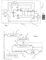
- the attached drawing shows an installation according to the invention and a method of controlling its power supply.
- Figure 1 is a diagram of the installation according to the invention.
- Figure 2 is a flow chart of a method of controlling the power supply of the installation according to the invention.
- the installation 1 shown in Figure 1 is intended for the operation of a door GD of a building or a gate.
- the installation mainly comprises a power circuit 2 and a control circuit 3.
- the AC voltage of the sector represented by the phase line P and the neutral line N is rectified by means REC full wave rectification means.
- the output voltage of the rectifying means enables the unidirectional charging of a capacitor CM through a controlled switch TR and means IL of limiting the charging current of the capacitor CM.
- the controlled switch TR is for example a MOS type transistor, whose maximum operating voltage is at least equal to that of the mains.
- the means IL make it possible to limit the intensity at the moment of the closing of the controlled switch TR.
- These means may comprise a simple resistance or more complex circuit as the primary of a unitary ratio transformer whose secondary current is added, after rectification, to the charging current of the capacitor CM.
- a MOT motor DC is connected across the capacitor CM during the phases in which it must operate. It drives the gate or the door GD via a reducer and a mechanical connection which are not represented.
- the contactor circuit for supplying in one direction or the other direction of the MOT motor by the UCM voltage across the capacitor CM is not shown, the contactor circuit for supplying in one direction or the other direction of the MOT motor by the UCM voltage across the capacitor CM .
- the controlled switch TR is controlled by the control circuit 3.
- This circuit can base its control law from the rectified mains voltage V1 taken just downstream of the rectifying means REC and / or the output voltage UCM. The law can also depend on the voltage V2 taken between the current limiting means IL and the controlled switch.
- a high state applied to the Reset input R causes a low state at the Q output of the flip-flop which blocks the transistor TR.
- a high state applied to the input S causes a high state at the Q output of the flip-flop, which makes the transistor TR conductive.
- a control unit UC whose outputs are the Set and Reset inputs of the RS flip-flop has been represented symbolically. This control unit receives at least two of the four signals represented: V1, V2, UCM, Q.
- the control unit UC comprises at least one voltage comparator at the inputs CA1, CA2, CA3 (one or more voltage references being used to compare the signals at these inputs). It may also include a circuit for measuring the time activated by the signal Q attacking a TRIG input.
- a power supply method of the installation is described with reference to FIG.
- the closing of the controlled switch TR is preferentially caused when the voltage of the rectified sector becomes lower than a voltage threshold VT1, this threshold crossing being detected during a test step 10.
- a test step 12 is performed to compare the output voltage UCM (or V2 since the controlled switch TR is conductive) to a value threshold VT2.
- the opening of the controlled switch TR is caused, in a step 14, as soon as the output voltage reaches this threshold VT2.
- An additional test step 13 is performed in the case where the output voltage has not yet reached the threshold voltage VT2. This test may concern either the input voltage V1 or the conduction time of the controlled switch.
- step 13 If the result of the test is negative, the process loops on step 13 or on step 12 (as represented by the arrow drawn in dashed lines in FIG. 2).
- the test compares it to a threshold value VT3 greater than VT1. Since the threshold value VT3 is greater than the threshold value VT1, once the transistor TR becomes conductive, it is tolerated that the current flowing through the controlled switch exceeds its normal value, corresponding to the moment when the controlled switch TR moves from the open state. in the closed state.
- the test relates to the conduction time TM of the controlled switch TR, it compares it with a threshold value of duration TT1 greater than the normal conduction time TT when the motor MOT absorbs the nominal current. Since the threshold value of duration TT1 is greater than the threshold value of duration TT, it is tolerated that the current exceeds the nominal current.
- the conduction time TM is measured by measuring the activation time of the input TRIG of the control unit UC.
- the voltage thresholds VT3 or conduction duration TT1 are preferably dynamically adjustable. This dynamic change of the threshold is represented by step 15 and is performed by the control unit.
- the voltage threshold VT3 or the duration threshold TT1 has a high value, allowing, for example, an overcurrent equal to 5 times the nominal current.
- the voltage threshold VT3 or the threshold of duration TT1 can be reduced, in an optional step 15, to a lower value allowing for example an overcurrent equal to 2 times the rated current. This modification can take place after an optional delay of a few milliseconds, for example 20 ms.
- the voltage threshold VT3 or the threshold of duration TT1 can be reduced to the initial high value allowing an overcurrent equal to 5 times the nominal current if during a given period (for example 3 s), during which the voltage threshold VT3 or the threshold duration TT1 allows an overcurrent equal to 2 times the nominal current, the opening of the controlled switch TR was not controlled by crossing the voltage threshold VT3 or threshold duration TT1.
- the thresholds can take more than two voltage values or more than two time values. The combination of the value of these thresholds and their duration of validity depends in particular on the thermal characteristics of the components. It is also possible that the voltage threshold VT3 or the threshold duration TT1 first allow a very large overcurrent and then become lower than the voltage threshold VT1 or time threshold allowing the nominal current.
- All or part of the control unit and the equivalent of the RS flip-flop can be integrated in a microcontroller, comprising comparators and a timer.
- This microcontroller can also be responsible for managing commands ordered by a user.
- the voltage V2 representing both the supply voltage (when the switch is open) and the output voltage (when the switch is closed).
- the inputs CA2 and TRIG of the control unit are used.
- the installation and its method of supplying electrical energy also make it possible to cancel the energy consumption of the power circuit when the motor is not in use. This advantage is all the more important as standards and respect for the environment make it necessary to drastically limit the standby consumption of equipment.
Landscapes
- Engineering & Computer Science (AREA)
- Power Engineering (AREA)
- Power-Operated Mechanisms For Wings (AREA)
- Dc-Dc Converters (AREA)
- Control Of Ac Motors In General (AREA)
Claims (16)
- Verfahren zum Steuern der elektrischen Versorgung einer Installation (1), die zum Betätigen einer Tür (GD) eines Gebäudes oder eines Tors bestimmt ist und mit Wechselspannung gespeist wird, mit einem Wechselspannungs-Gleichspannungs-Umformer und mit einem Gleichstrom-Motor (MOT), der mechanisch mit der Tür oder dem Tor verbunden ist, wobei der Umformer einen Gleichrichter (REC) und einen zwischen die Eingangsklemmen des Motors geschalteten Kondensator (CM) aufweist, welcher durch die gleichgerichtete Wechselspannung (V1) über einen Schalter (TR) geladen wird, der von einer Steuerschaltung (3) mit der Frequenz der gleichgerichteten Wechselspannung gesteuert wird, dadurch gekennzeichnet, dass das Öffnen der Schalters durch das zuerst auftretende Ereignis der beiden folgenden Ereignisse gesteuert wird, von denen jedes das Öffnen des Schalters bewirkt:- Wenn die Spannung (UCM) an den Klemmen des Kondensators (CM) eine erste Spannungsschwelle (VT2) überschreitet;- wenn eine andere physikalische Grösse (V1; TM) eine andere Schwelle (VT3; TT1) überschreitet, welche den Strom im Schalter begrenzt, um ihn vor Spitzenströmen zu schützen, die zu seiner Zerstörung führen könnten, dabei jedoch einen Strom zulässt, der stärker als der normale Strom ist.
- Verfahren nach Anspruch 1, dadurch gekennzeichnet, dass der Schalter (TR) geschlossen wird, wenn die gleichgerichtete Wechselspannung (V1) eine zweite Spannungsschwelle (VT1) unterschreitet.
- Verfahren nach Anspruch 1 oder 2, dadurch gekennzeichnet, dass es sich beim Überschreiten einer anderen Schwelle (VT3; TT1) durch eine andere physikalischen Grösse (UCM; TM) um das Überschreiten einer dritten Spannungsschwelle (VT3) durch die gleichgerichtete Wechselspannung (V1) handelt.
- Verfahren nach Anspruch 3, dadurch gekennzeichnet, dass die dritte Spannungsschwelle (VT3) während einer ersten Zeit grösser als die zweite Spannungsschwelle (VT1) ist.
- Verfahren nach Anspruch 3 oder 4, dadurch gekennzeichnet, dass die dritte Spannungsschwelle (VT3) beim Betrieb der Installation durch eine Steuereinheit (UC) modifiziert wird.
- Verfahren nach Anspruch 5, dadurch gekennzeichnet, dass die dritte Spannungsschwelle (VT3) durch die Steuereinheit (UC) geändert wird, nachdem die Öffnung des gesteuerten Schalters (TR) durch das Überschreiten dieser dritten Spannungsschwelle (VT3) durch die gleichgerichtete Wechselspannung (V1) ausgelöst worden ist.
- Verfahren nach Anspruch 1 oder 2, dadurch gekennzeichnet, dass es sich beim Überschreiten einer anderen Schwelle (VT3; TT1) durch eine andere physikalische Gösse (UCM; TM) um das Überschreiten einer Zeitdauerschwelle (TT1) durch die Zeitdauer (TM) handelt, während der sich der gesteuerte Schalter (TR) im leitenden Zustand befindet.
- Verfahren nach Anspruch 7, dadurch gekennzeichnet, dass die Zeitdauerschwelle (TT1) während einer ersten Zeit grösser ist als die Zeitdauer (TM) der Leitung des Schalters, wenn der Motor seinen Nennstrom aufnimmt.
- Verfahren nach Anspruch 7 oder 8, dadurch gekennzeichnet, dass die Zeitdauerschwelle (TT1) durch eine Steuereinheit (UC) beim Betrieb der Installation geändert wird.
- Verfahren nach Anspruch 9, dadurch gekennzeichnet, dass die Zeitdauerschwelle (TT1) durch die Steuereinheit (UC) geändert wird, nachdem das Öffnen des gesteuerten Schalters (TR) durch das Überschreiten dieser Zeitdauerschwelle (TT1) durch die Dauer (TM) der Leitung des gesteuerten Schalters (TR) ausgelöst wurde.
- Verfahren nach Anspruch 6 oder 10, dadurch gekennzeichnet, dass zwischen dem Öffnen des Schalters infolge des Überschreitens der Schwelle und der Änderung dieser Schwelle eine Verzögerung eingeführt wird.
- Verfahren nach Anspruch 11, dadurch gekennzeichnet, dass die Dauer dieser Verzögerung 20 ms beträgt.
- Verfahren nach einem der Ansprüche 6, 10, 11 oder 12, dadurch gekennzeichnet, dass die dritte Spannungsschwelle (VT3) oder die Zeitdauerschwelle (TT1) nach einer Verzögerung auf ihren Anfangswert zurückgeführt wird.
- Verfahren nach Anspruch 13, dadurch gekennzeichnet, dass die Zurückführung der dritten Spannungsschwelle (VT3) oder der Zeitdauerschwelle (TT1) auf ihren Anfangswert durch den Umstand bedingt ist, dass während dieser Periode das Öffnen des gesteuerten Schalters (TR) nicht durch das Überschreiten der dritten Spannungsschwelle (VT3) durch die gleichgerichtete Wechselspannung (V1) oder durch ein Überschreiten der Zeitdauerschwelle (TT1) durch die Dauer (TM) der Leitung des gesteuerten Schalters (TR) ausgelöst worden ist.
- Verfahren nach Anspruch 13 oder 14, dadurch gekennzeichnet, dass die Dauer der Verzögerung 3 s beträgt.
- Installation zur Betätigung einer Tür (GD) eines Gebäudes oder eines Tors, welche durch eine Wechselspannung gespeist wird, mit einem Wechselspannungs-Gleichspannungs-Umformer und mit einem Gleichstrommotor (MOT), der mechanisch mit der Tür oder dem Tor verbunden ist, wobei der Umformer einen Gleichrichter (REC) und einen zwischen die Eingangsklemmen des Motors geschalteten Kondensator (CM) aufweist, welcher durch die gleichgerichtete wechselspannung (V1) über einen Schalter (TR) geladen wird, der von einer Steuerschaltung (3) mit der Frequenz der gleichgerichteten Wechselspannung gesteuert wird, dadurch gekennzeichnet, dass die Steuerschaltung (3) mit einer Steuereinheit (UC) ausgerüstet ist, welche die Durchführung des Steuerverfahrens nach einem der Ansprüche 1 bis 15 erlaubt.
Applications Claiming Priority (2)
| Application Number | Priority Date | Filing Date | Title |
|---|---|---|---|
| FR0315058 | 2003-12-19 | ||
| FR0315058A FR2864371B1 (fr) | 2003-12-19 | 2003-12-19 | Installation destinee a la manoeuvre d'une porte de batiment et procede de commande de l'alimentation d'une telle installation |
Publications (2)
| Publication Number | Publication Date |
|---|---|
| EP1553688A1 EP1553688A1 (de) | 2005-07-13 |
| EP1553688B1 true EP1553688B1 (de) | 2006-10-04 |
Family
ID=34586425
Family Applications (1)
| Application Number | Title | Priority Date | Filing Date |
|---|---|---|---|
| EP04029011A Expired - Lifetime EP1553688B1 (de) | 2003-12-19 | 2004-12-08 | Installation zum betrieben einer Tür eines Gebaüde und Verfahren zur Steuerung der elektrischen Versorgung einer solchen Installation. |
Country Status (7)
| Country | Link |
|---|---|
| EP (1) | EP1553688B1 (de) |
| CN (1) | CN100449448C (de) |
| AT (1) | ATE341852T1 (de) |
| AU (1) | AU2004235593B2 (de) |
| DE (1) | DE602004002665T2 (de) |
| ES (1) | ES2245274T3 (de) |
| FR (1) | FR2864371B1 (de) |
Family Cites Families (9)
| Publication number | Priority date | Publication date | Assignee | Title |
|---|---|---|---|---|
| US4346342A (en) * | 1981-06-09 | 1982-08-24 | Rockwell International Corporation | Current limiting voltage regulator |
| DE3304759A1 (de) * | 1983-02-11 | 1984-08-16 | Siemens AG, 1000 Berlin und 8000 München | Verfahren und schaltungsanordnung zur transformatorlosen erzeugung kleiner gleichspannungen und deren verwendung |
| DE4028348A1 (de) * | 1990-09-06 | 1992-03-12 | Zumtobel Ag | Niederspannungsquelle mit vorschaltanordnung |
| US5181159A (en) * | 1990-12-24 | 1993-01-19 | General Electric Company | AC to DC converter having an enhanced power factor |
| DE19805927A1 (de) * | 1998-02-13 | 1999-10-28 | Thomson Brandt Gmbh | Schaltnetzteil |
| US6061259A (en) * | 1999-08-30 | 2000-05-09 | Demichele; Glenn | Protected transformerless AC to DC power converter |
| FR2828598B1 (fr) * | 2001-08-10 | 2003-12-05 | Somfy | Convertisseur electrique non regule |
| JP2005528875A (ja) * | 2002-06-04 | 2005-09-22 | コーニンクレッカ フィリップス エレクトロニクス エヌ ヴィ | Dc−dcコンバータ |
| DE10241778C1 (de) * | 2002-09-06 | 2003-11-27 | Adolf Tedsen Gmbh & Co Kg | Garagentorantrieb mit impulsweitengesteuertem Gleichstrommotor |
-
2003
- 2003-12-19 FR FR0315058A patent/FR2864371B1/fr not_active Expired - Fee Related
-
2004
- 2004-12-02 AU AU2004235593A patent/AU2004235593B2/en not_active Ceased
- 2004-12-08 DE DE602004002665T patent/DE602004002665T2/de not_active Expired - Lifetime
- 2004-12-08 ES ES04029011T patent/ES2245274T3/es not_active Expired - Lifetime
- 2004-12-08 AT AT04029011T patent/ATE341852T1/de not_active IP Right Cessation
- 2004-12-08 EP EP04029011A patent/EP1553688B1/de not_active Expired - Lifetime
- 2004-12-17 CN CNB2004100821245A patent/CN100449448C/zh not_active Expired - Fee Related
Also Published As
| Publication number | Publication date |
|---|---|
| ES2245274T1 (es) | 2006-01-01 |
| FR2864371B1 (fr) | 2006-10-27 |
| AU2004235593B2 (en) | 2009-02-19 |
| EP1553688A1 (de) | 2005-07-13 |
| DE602004002665T2 (de) | 2007-08-23 |
| CN100449448C (zh) | 2009-01-07 |
| AU2004235593A1 (en) | 2005-07-07 |
| ES2245274T3 (es) | 2007-05-01 |
| CN1641508A (zh) | 2005-07-20 |
| FR2864371A1 (fr) | 2005-06-24 |
| DE602004002665D1 (de) | 2006-11-16 |
| ATE341852T1 (de) | 2006-10-15 |
Similar Documents
| Publication | Publication Date | Title |
|---|---|---|
| EP0480847B1 (de) | Wechselstromenergieversorgungsanlage mit Notstromversorgung | |
| EP1950885B1 (de) | Steuervorrichtung eines elektronischen Leistungstrenners und eine solche Vorrichtung umfassender Stromrichter | |
| EP3577672B1 (de) | Hochspannungsgleichstromunterbrechungsvorrichtung | |
| FR2863115A1 (fr) | Interrupteur de circuit en cas de defaut a la terre. | |
| FR2932031A1 (fr) | Dispositif de precharge d'un convertisseur a decoupage, ensemble et aeronef le comportant. | |
| FR3012696A1 (fr) | Circuit de protection contre des surtensions | |
| WO2020164945A1 (fr) | Systeme de commutation statique et de limitation d'un courant continu | |
| FR2977996A1 (fr) | Convertisseur de puissance comportant un module onduleur a transistors a effet de champ normalement fermes | |
| WO2006005885A2 (fr) | Redresseur et systeme de controle de la vitesse d'un moteur electrique. | |
| EP0836280B1 (de) | Elektronischer Schalter mit Zweidraht-Versorgung | |
| EP1553688A1 (de) | Installation zum betrieben einer Tür eines Gebaüde und Verfahren zur Steuerung der elektrischen Versorgung einer solchen Installation. | |
| EP2200050B1 (de) | Verarbeitungseinheit, die mit Mitteln zur Steuerung eines elektromagnetischen Stellglieds ausgestattet ist, und elektromagnetisches Stellglied, das eine solche Verarbeitungseinheit umfasst | |
| EP3824522B1 (de) | Vorrichtung zur emulation eines bimetallstreifens und vorrichtung zum schutz einer elektrischen leitung gegen überspannungen | |
| FR2833426A1 (fr) | Alternateur d'automobile concu pour attenuer rapidement un courant de champ | |
| EP1530284B1 (de) | Verfahren und Vorrichtung zur Drehzahlregelung eines Motors für einen Rollladen | |
| EP1573892A1 (de) | Vorrichtung zum steuern der energieversorgung eines asynchronmotors | |
| EP3041102B1 (de) | Kapazitive einspeisevorrichtung zur steuerung eines elektrischen abschaltungsgeräts | |
| EP1357657A1 (de) | Vorrichtung zum Anhalten einer einphasigen Asynchronmaschine mit Kondensator | |
| EP3389076A1 (de) | Steuerverfahren und -vorrichtung eines stellglieds, und elektrisches schutzgerät, das eine solche vorrichtung umfasst | |
| EP2093870A1 (de) | Schutzvorrichtung eines stufenlosen Drehzahlreglers einschließlich Filterdrossel | |
| FR2622368A1 (fr) | Interrupteur differentiel selectif a courant de defaut | |
| EP1685645A1 (de) | Rolladen-bewegungssteuereinrichtung | |
| FR3083933A1 (fr) | Procede de reduction des perturbations electromagnetiques produites lors de la mise a l'etat passant d'un transistor | |
| WO2006018700A1 (fr) | Procede et dispositif d'alimentation d'un moteur electrique a courant continu | |
| EP4586297A1 (de) | Elektrische schutzvorrichtung und steuerungsverfahren dafür |
Legal Events
| Date | Code | Title | Description |
|---|---|---|---|
| PUAI | Public reference made under article 153(3) epc to a published international application that has entered the european phase |
Free format text: ORIGINAL CODE: 0009012 |
|
| AK | Designated contracting states |
Kind code of ref document: A1 Designated state(s): AT BE BG CH CY CZ DE DK EE ES FI FR GB GR HU IE IS IT LI LT LU MC NL PL PT RO SE SI SK TR |
|
| AX | Request for extension of the european patent |
Extension state: AL BA HR LV MK YU |
|
| 17P | Request for examination filed |
Effective date: 20050613 |
|
| AKX | Designation fees paid |
Designated state(s): AT BE BG CH CY CZ DE DK EE ES FI FR GB GR HU IE IS IT LI LT LU MC NL PL PT RO SE SI SK TR |
|
| GRAP | Despatch of communication of intention to grant a patent |
Free format text: ORIGINAL CODE: EPIDOSNIGR1 |
|
| GRAS | Grant fee paid |
Free format text: ORIGINAL CODE: EPIDOSNIGR3 |
|
| GRAA | (expected) grant |
Free format text: ORIGINAL CODE: 0009210 |
|
| AK | Designated contracting states |
Kind code of ref document: B1 Designated state(s): AT BE BG CH CY CZ DE DK EE ES FI FR GB GR HU IE IS IT LI LT LU MC NL PL PT RO SE SI SK TR |
|
| PG25 | Lapsed in a contracting state [announced via postgrant information from national office to epo] |
Ref country code: SI Free format text: LAPSE BECAUSE OF FAILURE TO SUBMIT A TRANSLATION OF THE DESCRIPTION OR TO PAY THE FEE WITHIN THE PRESCRIBED TIME-LIMIT Effective date: 20061004 Ref country code: RO Free format text: LAPSE BECAUSE OF FAILURE TO SUBMIT A TRANSLATION OF THE DESCRIPTION OR TO PAY THE FEE WITHIN THE PRESCRIBED TIME-LIMIT Effective date: 20061004 Ref country code: FI Free format text: LAPSE BECAUSE OF FAILURE TO SUBMIT A TRANSLATION OF THE DESCRIPTION OR TO PAY THE FEE WITHIN THE PRESCRIBED TIME-LIMIT Effective date: 20061004 Ref country code: SK Free format text: LAPSE BECAUSE OF FAILURE TO SUBMIT A TRANSLATION OF THE DESCRIPTION OR TO PAY THE FEE WITHIN THE PRESCRIBED TIME-LIMIT Effective date: 20061004 Ref country code: IE Free format text: LAPSE BECAUSE OF FAILURE TO SUBMIT A TRANSLATION OF THE DESCRIPTION OR TO PAY THE FEE WITHIN THE PRESCRIBED TIME-LIMIT Effective date: 20061004 Ref country code: LT Free format text: LAPSE BECAUSE OF FAILURE TO SUBMIT A TRANSLATION OF THE DESCRIPTION OR TO PAY THE FEE WITHIN THE PRESCRIBED TIME-LIMIT Effective date: 20061004 Ref country code: AT Free format text: LAPSE BECAUSE OF FAILURE TO SUBMIT A TRANSLATION OF THE DESCRIPTION OR TO PAY THE FEE WITHIN THE PRESCRIBED TIME-LIMIT Effective date: 20061004 Ref country code: PL Free format text: LAPSE BECAUSE OF FAILURE TO SUBMIT A TRANSLATION OF THE DESCRIPTION OR TO PAY THE FEE WITHIN THE PRESCRIBED TIME-LIMIT Effective date: 20061004 Ref country code: NL Free format text: LAPSE BECAUSE OF FAILURE TO SUBMIT A TRANSLATION OF THE DESCRIPTION OR TO PAY THE FEE WITHIN THE PRESCRIBED TIME-LIMIT Effective date: 20061004 Ref country code: CZ Free format text: LAPSE BECAUSE OF FAILURE TO SUBMIT A TRANSLATION OF THE DESCRIPTION OR TO PAY THE FEE WITHIN THE PRESCRIBED TIME-LIMIT Effective date: 20061004 |
|
| REG | Reference to a national code |
Ref country code: GB Ref legal event code: FG4D Free format text: NOT ENGLISH |
|
| REG | Reference to a national code |
Ref country code: CH Ref legal event code: EP |
|
| REG | Reference to a national code |
Ref country code: IE Ref legal event code: FG4D Free format text: LANGUAGE OF EP DOCUMENT: FRENCH |
|
| REF | Corresponds to: |
Ref document number: 602004002665 Country of ref document: DE Date of ref document: 20061116 Kind code of ref document: P |
|
| PG25 | Lapsed in a contracting state [announced via postgrant information from national office to epo] |
Ref country code: BE Free format text: LAPSE BECAUSE OF NON-PAYMENT OF DUE FEES Effective date: 20061231 Ref country code: MC Free format text: LAPSE BECAUSE OF NON-PAYMENT OF DUE FEES Effective date: 20061231 |
|
| PG25 | Lapsed in a contracting state [announced via postgrant information from national office to epo] |
Ref country code: SE Free format text: LAPSE BECAUSE OF FAILURE TO SUBMIT A TRANSLATION OF THE DESCRIPTION OR TO PAY THE FEE WITHIN THE PRESCRIBED TIME-LIMIT Effective date: 20070104 Ref country code: BG Free format text: LAPSE BECAUSE OF FAILURE TO SUBMIT A TRANSLATION OF THE DESCRIPTION OR TO PAY THE FEE WITHIN THE PRESCRIBED TIME-LIMIT Effective date: 20070104 Ref country code: DK Free format text: LAPSE BECAUSE OF FAILURE TO SUBMIT A TRANSLATION OF THE DESCRIPTION OR TO PAY THE FEE WITHIN THE PRESCRIBED TIME-LIMIT Effective date: 20070104 |
|
| PG25 | Lapsed in a contracting state [announced via postgrant information from national office to epo] |
Ref country code: IS Free format text: LAPSE BECAUSE OF FAILURE TO SUBMIT A TRANSLATION OF THE DESCRIPTION OR TO PAY THE FEE WITHIN THE PRESCRIBED TIME-LIMIT Effective date: 20070204 |
|
| PG25 | Lapsed in a contracting state [announced via postgrant information from national office to epo] |
Ref country code: PT Free format text: LAPSE BECAUSE OF FAILURE TO SUBMIT A TRANSLATION OF THE DESCRIPTION OR TO PAY THE FEE WITHIN THE PRESCRIBED TIME-LIMIT Effective date: 20070316 |
|
| NLV1 | Nl: lapsed or annulled due to failure to fulfill the requirements of art. 29p and 29m of the patents act | ||
| REG | Reference to a national code |
Ref country code: ES Ref legal event code: FG2A Ref document number: 2245274 Country of ref document: ES Kind code of ref document: T3 |
|
| GBV | Gb: ep patent (uk) treated as always having been void in accordance with gb section 77(7)/1977 [no translation filed] |
Effective date: 20061004 |
|
| REG | Reference to a national code |
Ref country code: IE Ref legal event code: FD4D |
|
| PLBE | No opposition filed within time limit |
Free format text: ORIGINAL CODE: 0009261 |
|
| STAA | Information on the status of an ep patent application or granted ep patent |
Free format text: STATUS: NO OPPOSITION FILED WITHIN TIME LIMIT |
|
| 26N | No opposition filed |
Effective date: 20070705 |
|
| PG25 | Lapsed in a contracting state [announced via postgrant information from national office to epo] |
Ref country code: GB Free format text: LAPSE BECAUSE OF FAILURE TO SUBMIT A TRANSLATION OF THE DESCRIPTION OR TO PAY THE FEE WITHIN THE PRESCRIBED TIME-LIMIT Effective date: 20061004 |
|
| BERE | Be: lapsed |
Owner name: SOMFY SAS Effective date: 20061231 |
|
| PG25 | Lapsed in a contracting state [announced via postgrant information from national office to epo] |
Ref country code: GR Free format text: LAPSE BECAUSE OF FAILURE TO SUBMIT A TRANSLATION OF THE DESCRIPTION OR TO PAY THE FEE WITHIN THE PRESCRIBED TIME-LIMIT Effective date: 20070105 |
|
| PG25 | Lapsed in a contracting state [announced via postgrant information from national office to epo] |
Ref country code: EE Free format text: LAPSE BECAUSE OF FAILURE TO SUBMIT A TRANSLATION OF THE DESCRIPTION OR TO PAY THE FEE WITHIN THE PRESCRIBED TIME-LIMIT Effective date: 20061004 |
|
| PG25 | Lapsed in a contracting state [announced via postgrant information from national office to epo] |
Ref country code: LU Free format text: LAPSE BECAUSE OF NON-PAYMENT OF DUE FEES Effective date: 20061208 Ref country code: TR Free format text: LAPSE BECAUSE OF FAILURE TO SUBMIT A TRANSLATION OF THE DESCRIPTION OR TO PAY THE FEE WITHIN THE PRESCRIBED TIME-LIMIT Effective date: 20061004 Ref country code: HU Free format text: LAPSE BECAUSE OF FAILURE TO SUBMIT A TRANSLATION OF THE DESCRIPTION OR TO PAY THE FEE WITHIN THE PRESCRIBED TIME-LIMIT Effective date: 20070405 |
|
| PG25 | Lapsed in a contracting state [announced via postgrant information from national office to epo] |
Ref country code: CY Free format text: LAPSE BECAUSE OF FAILURE TO SUBMIT A TRANSLATION OF THE DESCRIPTION OR TO PAY THE FEE WITHIN THE PRESCRIBED TIME-LIMIT Effective date: 20061004 |
|
| REG | Reference to a national code |
Ref country code: CH Ref legal event code: PL |
|
| PG25 | Lapsed in a contracting state [announced via postgrant information from national office to epo] |
Ref country code: LI Free format text: LAPSE BECAUSE OF NON-PAYMENT OF DUE FEES Effective date: 20081231 Ref country code: CH Free format text: LAPSE BECAUSE OF NON-PAYMENT OF DUE FEES Effective date: 20081231 |
|
| PGFP | Annual fee paid to national office [announced via postgrant information from national office to epo] |
Ref country code: ES Payment date: 20091223 Year of fee payment: 6 |
|
| PGFP | Annual fee paid to national office [announced via postgrant information from national office to epo] |
Ref country code: IT Payment date: 20091221 Year of fee payment: 6 |
|
| PGFP | Annual fee paid to national office [announced via postgrant information from national office to epo] |
Ref country code: DE Payment date: 20100114 Year of fee payment: 6 |
|
| REG | Reference to a national code |
Ref country code: DE Ref legal event code: R119 Ref document number: 602004002665 Country of ref document: DE Effective date: 20110701 |
|
| PG25 | Lapsed in a contracting state [announced via postgrant information from national office to epo] |
Ref country code: DE Free format text: LAPSE BECAUSE OF NON-PAYMENT OF DUE FEES Effective date: 20110701 |
|
| PG25 | Lapsed in a contracting state [announced via postgrant information from national office to epo] |
Ref country code: IT Free format text: LAPSE BECAUSE OF NON-PAYMENT OF DUE FEES Effective date: 20101208 |
|
| REG | Reference to a national code |
Ref country code: ES Ref legal event code: FD2A Effective date: 20120206 |
|
| PG25 | Lapsed in a contracting state [announced via postgrant information from national office to epo] |
Ref country code: ES Free format text: LAPSE BECAUSE OF NON-PAYMENT OF DUE FEES Effective date: 20101209 |
|
| PGFP | Annual fee paid to national office [announced via postgrant information from national office to epo] |
Ref country code: FR Payment date: 20131204 Year of fee payment: 10 |
|
| REG | Reference to a national code |
Ref country code: FR Ref legal event code: ST Effective date: 20150831 |
|
| PG25 | Lapsed in a contracting state [announced via postgrant information from national office to epo] |
Ref country code: FR Free format text: LAPSE BECAUSE OF NON-PAYMENT OF DUE FEES Effective date: 20141231 |