EP1553781A2 - Méthode et Procédé pour traitement d'images digitales a mouvement par prédiction de l'erreur de compensation de mouvement utilisant un bloc précédent. - Google Patents
Méthode et Procédé pour traitement d'images digitales a mouvement par prédiction de l'erreur de compensation de mouvement utilisant un bloc précédent. Download PDFInfo
- Publication number
- EP1553781A2 EP1553781A2 EP04257499A EP04257499A EP1553781A2 EP 1553781 A2 EP1553781 A2 EP 1553781A2 EP 04257499 A EP04257499 A EP 04257499A EP 04257499 A EP04257499 A EP 04257499A EP 1553781 A2 EP1553781 A2 EP 1553781A2
- Authority
- EP
- European Patent Office
- Prior art keywords
- error image
- motion compensation
- error
- predicted
- block
- Prior art date
- Legal status (The legal status is an assumption and is not a legal conclusion. Google has not performed a legal analysis and makes no representation as to the accuracy of the status listed.)
- Withdrawn
Links
Images


Classifications
-
- H—ELECTRICITY
- H04—ELECTRIC COMMUNICATION TECHNIQUE
- H04N—PICTORIAL COMMUNICATION, e.g. TELEVISION
- H04N19/00—Methods or arrangements for coding, decoding, compressing or decompressing digital video signals
- H04N19/50—Methods or arrangements for coding, decoding, compressing or decompressing digital video signals using predictive coding
- H04N19/503—Methods or arrangements for coding, decoding, compressing or decompressing digital video signals using predictive coding involving temporal prediction
- H04N19/51—Motion estimation or motion compensation
- H04N19/567—Motion estimation based on rate distortion criteria
-
- H—ELECTRICITY
- H04—ELECTRIC COMMUNICATION TECHNIQUE
- H04N—PICTORIAL COMMUNICATION, e.g. TELEVISION
- H04N19/00—Methods or arrangements for coding, decoding, compressing or decompressing digital video signals
- H04N19/10—Methods or arrangements for coding, decoding, compressing or decompressing digital video signals using adaptive coding
- H04N19/134—Methods or arrangements for coding, decoding, compressing or decompressing digital video signals using adaptive coding characterised by the element, parameter or criterion affecting or controlling the adaptive coding
- H04N19/136—Incoming video signal characteristics or properties
- H04N19/14—Coding unit complexity, e.g. amount of activity or edge presence estimation
-
- H—ELECTRICITY
- H04—ELECTRIC COMMUNICATION TECHNIQUE
- H04N—PICTORIAL COMMUNICATION, e.g. TELEVISION
- H04N19/00—Methods or arrangements for coding, decoding, compressing or decompressing digital video signals
- H04N19/10—Methods or arrangements for coding, decoding, compressing or decompressing digital video signals using adaptive coding
- H04N19/102—Methods or arrangements for coding, decoding, compressing or decompressing digital video signals using adaptive coding characterised by the element, parameter or selection affected or controlled by the adaptive coding
- H04N19/103—Selection of coding mode or of prediction mode
- H04N19/105—Selection of the reference unit for prediction within a chosen coding or prediction mode, e.g. adaptive choice of position and number of pixels used for prediction
-
- H—ELECTRICITY
- H04—ELECTRIC COMMUNICATION TECHNIQUE
- H04N—PICTORIAL COMMUNICATION, e.g. TELEVISION
- H04N19/00—Methods or arrangements for coding, decoding, compressing or decompressing digital video signals
- H04N19/10—Methods or arrangements for coding, decoding, compressing or decompressing digital video signals using adaptive coding
- H04N19/102—Methods or arrangements for coding, decoding, compressing or decompressing digital video signals using adaptive coding characterised by the element, parameter or selection affected or controlled by the adaptive coding
- H04N19/119—Adaptive subdivision aspects, e.g. subdivision of a picture into rectangular or non-rectangular coding blocks
-
- H—ELECTRICITY
- H04—ELECTRIC COMMUNICATION TECHNIQUE
- H04N—PICTORIAL COMMUNICATION, e.g. TELEVISION
- H04N19/00—Methods or arrangements for coding, decoding, compressing or decompressing digital video signals
- H04N19/10—Methods or arrangements for coding, decoding, compressing or decompressing digital video signals using adaptive coding
- H04N19/169—Methods or arrangements for coding, decoding, compressing or decompressing digital video signals using adaptive coding characterised by the coding unit, i.e. the structural portion or semantic portion of the video signal being the object or the subject of the adaptive coding
- H04N19/17—Methods or arrangements for coding, decoding, compressing or decompressing digital video signals using adaptive coding characterised by the coding unit, i.e. the structural portion or semantic portion of the video signal being the object or the subject of the adaptive coding the unit being an image region, e.g. an object
- H04N19/176—Methods or arrangements for coding, decoding, compressing or decompressing digital video signals using adaptive coding characterised by the coding unit, i.e. the structural portion or semantic portion of the video signal being the object or the subject of the adaptive coding the unit being an image region, e.g. an object the region being a block, e.g. a macroblock
-
- H—ELECTRICITY
- H04—ELECTRIC COMMUNICATION TECHNIQUE
- H04N—PICTORIAL COMMUNICATION, e.g. TELEVISION
- H04N19/00—Methods or arrangements for coding, decoding, compressing or decompressing digital video signals
- H04N19/50—Methods or arrangements for coding, decoding, compressing or decompressing digital video signals using predictive coding
- H04N19/503—Methods or arrangements for coding, decoding, compressing or decompressing digital video signals using predictive coding involving temporal prediction
- H04N19/51—Motion estimation or motion compensation
-
- H—ELECTRICITY
- H04—ELECTRIC COMMUNICATION TECHNIQUE
- H04N—PICTORIAL COMMUNICATION, e.g. TELEVISION
- H04N19/00—Methods or arrangements for coding, decoding, compressing or decompressing digital video signals
- H04N19/50—Methods or arrangements for coding, decoding, compressing or decompressing digital video signals using predictive coding
- H04N19/593—Methods or arrangements for coding, decoding, compressing or decompressing digital video signals using predictive coding involving spatial prediction techniques
-
- H—ELECTRICITY
- H04—ELECTRIC COMMUNICATION TECHNIQUE
- H04N—PICTORIAL COMMUNICATION, e.g. TELEVISION
- H04N19/00—Methods or arrangements for coding, decoding, compressing or decompressing digital video signals
- H04N19/60—Methods or arrangements for coding, decoding, compressing or decompressing digital video signals using transform coding
- H04N19/61—Methods or arrangements for coding, decoding, compressing or decompressing digital video signals using transform coding in combination with predictive coding
Definitions
- the present invention relates to processing of an image, and more particularly, to a digital motion picture processing method and apparatus for coding and decoding a digital motion picture.
- FIG. 1 is a view for explaining an example of a motion compensation (MC) error.
- MC motion compensation
- an MC error in an MC error image which is the result of removing temporal redundancy in a digital motion picture, is greatly distributed around the edge of an object that is moving within the MC error image.
- the great distribution of the MC error results because motion estimation and motion compensation are performed for each macroblock (MB) and respective MBs have one motion vector during coding of a motion picture.
- a relatively large MC error may occur due to motion component, among the motion components included in an MB, that is not reflected in one motion vector.
- DCT Discrete Cosine Transform
- a conventional method of coding and decoding a digital motion picture may deteriorate the effect of DCT.
- the present invention provides a method and apparatus for processing a digital motion picture that improve coding efficiency of the digital motion picture.
- a method of processing a digital motion picture including: when the digital motion picture is coded, dividing a motion compensation error image, which is the result of removing temporal redundancy of the digital motion picture, into horizontal or vertical blocks, predicting a motion compensation error of a current block using a previous block neighboring by a unit pixel distance to the current block, and performing an orthogonal transform on a predicted error image consisting of the predicted motion compensation errors; and when the coded digital motion picture is decoded, recovering the predicted error image by performing an inverse orthogonal transform and recovering the motion compensation error image from the recovered predicted error image.
- the current block means a block to be currently processed
- the previous block means a block previously processed.
- an apparatus for processing a digital motion picture including: a coder which divides a motion compensation error image, which is a result of removing temporal redundancy of the digital motion picture, into horizontal or vertical blocks, predicts a motion compensation error of a current block using a previous block neighboring by a unit pixel distance to the current block, and performs an orthogonal transform on a predicted error image consisting of the predicted motion compensation errors; and a decoder which recovers the predicted error image by performing an inverse orthogonal transform and recovers the motion compensation error image from the recovered predicted error image.
- FIG. 2 is a flowchart of a method of processing a digital motion picture, according to a preferred embodiment of the present invention.
- the method includes step 10 of coding a digital motion picture and step 12 of decoding the coded digital motion picture.
- a digital motion picture is coded.
- an MC error image which is the result of removing temporal redundancy between digital motion pictures neighboring in time, is divided into blocks.
- the blocks may be horizontal or vertical blocks, which will be described later.
- An MC error of a block to be currently processed (hereinafter referred to as a current block) is predicted using a neighboring block at a distance of one that was previously processed (hereinafter referred to as a previous block).
- An orthogonal transform (OT) is performed on a predicted error image consisting of the predicted MC errors.
- the result of removing the temporal redundancy from the digital motion picture is obtained using a motion vector that is generated from the digital motion picture. This is disclosed in standards such as MPEG-1, -2, and -4, Video, H.261, H.263, and H.264.
- each MB is segmented into horizontal or vertical blocks.
- an MC error of each of horizontal or vertical blocks to be currently processed is predicted using a horizontal or vertical block that was previously processed and that neighbors the horizontal or vertical block by one pixel.
- all MC errors are predicted for the respective horizontal or vertical blocks of each of the MBs the MC error image includes to determine a predicted error image consisting of the predicted MC errors for the MC error image.
- step 12 when the coded digital motion picture is decoded, the predicted error image is recovered by performing an inverse orthogonal transform (IOT), and the MC error image is recovered from the recovered predicted error image.
- IOT inverse orthogonal transform
- FIGS. 3A through 3C are graphs for explaining correlations between neighboring pixels.
- FIG. 3A shows correlation between neighboring pixels at a unit pixel distance from a reference pixel in all directions
- FIG. 3B shows correlation between neighboring pixels at twice a unit pixel distance from a reference pixel in all directions
- FIG. 3C shows correlation between pixels closest to a reference pixel in all directions.
- luminance level error values ref_i of neighboring pixels at a unit pixel distance from a reference pixel are plotted along the horizontal axis
- a luminance level error value i of the neighboring pixel is plotted along the vertical axis.
- luminance level error values ref_ i(i-2) of neighboring pixels at twice a unit pixel distance from a reference pixel are plotted along the horizontal axis, and a luminance level error value i of the neighboring pixel is plotted along the vertical axis.
- a correlation coefficient of the data graphed in FIG. 3A is relatively large: 0.510.
- the large value of the correlation coefficient indicates that the correlation between neighboring pixels at a unit pixel distance is high.
- the correlation coefficient of the data graphed in FIG. 3B is very small: 0.032, meaning that the correlation between neighboring pixels at twice a unit pixel distance is low.
- the correlation coefficient of the data graphed in FIG. 3C is very high: 0.861, indicating that the correlation between pixels similar to the reference pixel among neighboring pixels at a unit pixel distance from the reference pixel are very high.
- an MC error of a current block is predicted using a previous block neighboring by a unit pixel distance to the current block when the digital motion picture is coded.
- FIG. 4 is a flowchart of a preferred embodiment 10A of step 10 of the method of FIG. 2.
- Step 10A includes step 30 of removing temporal redundancy of a digital motion picture, steps 32, 34, and 36 of removing spacial redundancy of the digital motion picture, and step 38 of performing variable length coding (VLC).
- VLC variable length coding
- step 30 temporal redundancy of a digital motion picture is removed and the resulting image is determined as an MC error image.
- step 32 the MC error image is divided into horizontal or vertical blocks and an MC error of a current horizontal or vertical block is predicted using a previous horizontal or vertical block neighboring by a unit pixel distance to the current horizontal block, to obtain a predicted error image consisting of the predicted MC errors.
- step 34 an OT is performed on the predicted error image.
- the OT may be a DCT or the like and may contribute to concentrating energy and diminishing correlation between pixels.
- step 36 the result of the OT is quantized.
- the result of the OT can be compressed by performing quantization corresponding to information concerning a quantization magnitude or the like that may be input from an external source.
- steps 32, 34, and 36 are performed to remove spatial redundancy from the result of removing temporal redundancy of a digital motion picture.
- step 38 VLC is performed on the quantization results so as to be suitable for a predetermined bit rate.
- step 38 is performed to remove statistical redundancy from the result of removing spatial redundancy.
- FIG. 5 is a flowchart of a preferred embodiment 12A of step 12 of the method of FIG. 2, according to the present invention.
- Step 12A includes steps 50 and 52 of performing variable length decoding (VLD) and inverse quantization, and steps 54, 56, and 58 of recovering a predicted error image, an MC error image, and a digital motion picture.
- VLD variable length decoding
- step 50 VLD is performed on the result of VLC.
- Step 10 of the method of FIG. 2, or step 10A shown in FIG. 4 may be performed by a coder (not shown), and step 12 of the method of FIG. 2, or step 12A shown in FIG. 5, may be performed by a decoder (not shown).
- the result of final coding by the coder i.e., the result of VLC
- the decoder reads and decodes the result of VLC which is transmitted from the coder or stored in the additional storage.
- step 52 the result of VLD is inverse-quantized.
- step 54 IOT is performed on the inverse quantization results to recover a predicted error image.
- step 56 an MC error image is recovered from the recovered predicted error image.
- step 58 a digital motion picture is recovered using the recovered MC error image.
- Step 10 of coding the digital motion picture in the method of FIG. 2 will be explained in more detail with reference to the attached drawings.
- FIG. 6 is a flowchart of a preferred embodiment of step 10 of the method of FIG. 2, or step 32 shown in FIG. 4, according to the present invention, including step 70 of determining a direction along which an MC error image is to be analyzed and step 72 of predicting MC errors.
- step 70 a determination is made as to whether each of MBs of which an MC error image consists is divided into horizontal or vertical blocks.
- FIG. 7 is a diagram of an example of an MC error image 76 which consists of MBs 78, an MB 80 being segmented into vertical blocks, and an MB 82 being segmented into horizontal blocks.
- the MC error image 76 consists of a plurality of MBs 78 and has a predetermined width and height.
- each of the MBs 78 has an N ⁇ M (breadth ⁇ length) size, where N and M may or may not be equal. According to most standards, N and M are each "16.”
- N and M are each "16.”
- each of the MBs 78 may be determined to be divided into vertical or horizontal blocks.
- the MB 80 consists of vertical blocks 96 with respect to a luminance component Y, vertical blocks 98 with respect to a color component U, and vertical blocks 100 with respect to a color component V.
- the length M/2 of each of the vertical blocks 98 or 100 with respect to the color component U or V may be half the length M of each of the vertical blocks 96 with respect to the luminance component Y.
- the MB 82 consists of horizontal blocks 116 with respect to a luminance component Y, horizontal blocks 118 with respect to a color component U, and horizontal blocks 120 with respect to a color component V.
- the width N/2 of each of the horizontal blocks 118 or 120 with respect to the color component U or V may be half the width N of each of the horizontal blocks 116 with respect to the luminance component Y.
- FIG. 8 is a flowchart of a preferred embodiment 70A of step 70 of FIG. 6, according to the present invention, including step 140 of calculating first and second sums S1 and S2 and steps 142, 144, 146, 148, and 150 of determining a direction along which an MB is to be analyzed according to sizes of the first and second sums S1 and S2.
- FIG. 9 is a diagram of an example of an arbitrary MB 78 to aid in understanding a process of calculating the first and second sums S1 and S2 of FIG. 8.
- the MB 78 includes N ⁇ M luminance error values Z 11 , Z 12 , ..., Z 1N , Z 21 , Z 22 , ..., Z 2N , ..., Z M1 , Z M2 , ..., and Z MN .
- step 140 absolute values of differences between luminance error values of horizontally neighboring pixels of FIG. 9 in the MB 78 are summed as shown in Equation 1 to obtain the first sum S1, and absolute values of differences between luminance error values of vertically neighboring pixels of FIG. 9 are summed as shown in Equation 2 to obtain the second sum S2.
- step 142 a determination is made as to whether the first sum S1 is larger than the second sum S2. If it is determined in step 142 that the first sum S1 is larger than the second sum S2, it is determined in step 146 to divide the MB 78 into horizontal blocks 82 as shown in FIG. 7.
- step 142 If it is determined in step 142 that the first sum S1 is not larger than the second sum S2, a determination is made in step 144 as to whether the first sum S1 is smaller than the second sum S2. If it is determined in step 144 that the first sum S1 is smaller than the second sum S2, it is determined in step 148 to divide the MB 78 into vertical blocks 80 as shown in FIG. 7. If it is determined that the first sum S1 is equal to the second sum S2, it is determined in step 150 to divide the MB 78 into predetermined horizontal or vertical blocks. The predetermined horizontal or vertical blocks are the result of determining in advance whether to divide the MB 78 into horizontal blocks or into vertical blocks when the first sum S1 is equal to the second sum S2.
- step 72 an MC error of a current block is predicted using a previous block neighboring by a unit pixel distance to the current block to obtain a predicted error image consisting of the predicted MC errors.
- FIG. 10 is a flowchart of a preferred embodiment 72A of step 72 of FIG. 6, according to the present invention, including steps 170, 172, and 174 of predicting MC errors using luminance error values and reference values.
- step 72 of FIG. 6 may include only steps 172 and 174 of FIG. 10.
- a reference value of each of pixels included in a current horizontal or vertical block is calculated using locally recovered luminance error values of pixels included in a previous horizontal or vertical block.
- the coder generally includes a local decoding unit (not shown) which performs the same operation as the decoder.
- the local decoding unit recovers the same luminance error values to be recovered by the decoder, which when recovered by the local decoding unit are called locally recovered luminance error values.
- step 174 the reference value is subtracted from a luminance error value of each of the pixels included in the current horizontal or vertical block and the subtraction result is determined as a predicted MC error of the corresponding pixel.
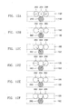
- FIGS. 11A through 11 E are diagrams of examples of horizontal blocks to aid in understanding step 72 of FIG. 6.
- FIG. 11A shows an example of the horizontal block 116, 118, or 120 which has been divided to analyze the MB 78 in a horizontal direction.
- reference numeral 190 denotes a previous block
- reference numeral 192 denotes a current block.
- FIG. 11B shows pixels a0, a1, a2, a3, a4, a5, a6, a7, a8, a9, a10, a11, a12, a13, a14, and a15 in a current horizontal block 192A which are classified into a group 210.
- FIG. 1 shows an example of the horizontal block 116, 118, or 120 which has been divided to analyze the MB 78 in a horizontal direction.
- reference numeral 190 denotes a previous block
- reference numeral 192 denotes a current block.
- FIG. 11B shows pixels a0, a1, a2, a3, a4, a5, a6, a7, a8, a
- FIG. 11 C shows pixels a0, a1, a2, a3, a4, a5, a6, a7, b0, b1, b2, b3, b4, b5, b6, and b7 in a current horizontal block 192B which are classified into groups 212 and 214.
- FIG. 11D shows pixels a0, a1, a2, a3, b0, b1, b2, and b3, c0, c1, c2, c3, d0, d1, d2, and d3 in a current horizontal block 192C which are classified into groups 216, 218, 220, and 222.
- 11E shows pixels a0, a1, b0, b1, c0, c1, d0, d1, e0, e1, f0, f1, g0, g1, h0, and h1 in a current horizontal block 192D which are classified into groups 226, 228, 230, 232, 234, 236, 238, and 240.
- step 72 of FIG. 6 may include steps 170, 172, and 174 of FIG. 10.
- step 170 pixels in a current block are classified into at least one group, for example, a predetermined number of groups.
- the predetermined number may be determined by a user. For example, pixels a0, a1, a2, a3, a4, a5, a6, a7, a8, a9, a10, a11, a12, a13, a14, and a15 in the CURRENT BLOCK 192 of a current horizontal block may be classified into one, two, four, or eight groups as shown in FIG. 11 B, 11C, 11D, or 11E.
- step 172 locally recovered luminance error values of pixels included in a previous block are analyzed in a predetermined direction, which is equally applied to each of groups of pixels, to obtain a reference value.
- the predetermined direction may be determined by the user.
- the locally recovered luminance error values of the pixels in the horizontal block 190A are analyzed in the straight line direction.
- a reference value of each of pixels in the groups 212, 214, 216, 218, 220, 222, 226, 228, 230, 232, 234, 236, 238, and 240 of FIGS. 11 C through 11E is calculated, locally recovered luminance error values of pixels included in a previous horizontal block 190B, 190C, or 190D are analyzed in the same direction.
- a reference value of each of pixels in a first processed block 90, 92, 94, 110, 112, or 114 in the MB 80 or 82 of FIG. 7 may be set to "0" because there is no previous block.
- FIGS. 12A through 12F show preferred embodiments of step 172 shown in FIG. 10 of calculating a reference value r(x) .
- the horizontal direction in each of FIGS. 12A through 12F denotes a position.
- r ( x ) p ( x ) wherein p(x) denotes a locally recovered luminance error value of the pixel 264 at position x of the previous block 190.
- a predetermined direction along which the previous block 190 is to be analyzed is a straight line direction.
- a predetermined direction along which the previous block 190 is to be analyzed is a leftward inclined direction.
- a predetermined direction along which the previous block 190 is to be analyzed is a rightward inclined direction.
- a predetermined direction along which the previous block 190 is to be analyzed is a leftward inclined direction.
- a predetermined direction along which the previous block 190 is to be analyzed is a rightward inclined direction.
- Step 12 of decoding the digital motion picture in the method of FIG. 2 will now be described in more detail with reference to the attached drawings.
- FIG. 13 is a flowchart for explaining a preferred embodiment of step 12 of the method of FIG. 2, or step 56 of FIG. 5, according to the present invention, including step 280 of interpreting first and second direction information and steps 282 and 284 of recovering reference values and an MC error image.
- first and second direction information is interpreted.
- the first direction information indicates whether the coer divides each of MBs of an MC error image into horizontal or vertical blocks.
- the second direction information indicates a predetermined direction along which locally recovered luminance error values of pixels included in a previous block are analyzed when the coder calculates reference values.
- the first and second direction information may be coded in step 10 of coding the digital motion picture, and decoded in step 50 of FIG. 5.
- step 282 reference values are recovered using the interpreted second direction information and recovered luminance error values of pixels in a previous block.
- the recovered luminance error values refers to luminance error values which are recovered by the decoder:
- the second direction information is interpreted to infer a predetermined direction along which a previous block has been analyzed when the coder generates reference values, and the reference values are recovered using the inferred predetermined direction and recovered luminance error values.
- an MC error image is recovered using the recovered reference values, the interpreted first direction information, and a recovered predicted error image. For example, recovered reference values and a recovered predicted error image are added to recover luminance error values of each of blocks of an MC error image, and the luminance error values recovered in all blocks are then put together in a horizontal or vertical direction, as inferred from the interpreted first direction information, to recover the MC error image.
- FIG. 14 is a block diagram of an apparatus for processing a digital motion picture according to the present invention.
- the apparatus includes a coder 300 and a decoder 302.
- the apparatus of FIG. 14 performs the method of FIG. 2.
- the coder 300 receives an MC error image, which is the result of removing temporal redundancy of a digital motion picture, via an input node IN1, divides the MC error image into horizontal or vertical blocks, predicts an MC error of a current block using a previous block neighboring by a unit pixel distance to the current block, performs OT on a predict error image consisting of the predicted MC errors, and outputs the coded result to the decoder 302.
- the decoder 302 recovers the predicted error image by performing IOT, recovers the MC error image from the recovered predicted error image, and outputs the recovered digital motion picture via an output node OUT1.
- FIG. 15 is a block diagram of a preferred embodiment 300A of the coder 300 of FIG. 14, including a motion estimator and compensator 320, a predicted error image generator 322, an OT unit 324, a quantizer 326, and a VLC unit 328.
- the coder 300A of FIG. 15 performs step 10A shown in FIG. 4.
- the motion estimator and compensator 320 removes temporal redundancy of a digital motion picture, which is input via an input node IN2, and outputs the result as an MC error image to the predicted error image generator 322.
- the predicted error image generator 322 receives the MC error image from the motion estimator and compensator 320, divides the MC error image into horizontal or vertical blocks, predicts an MC error of a current block using a previous block neighboring by a unit pixel distance to the current block, and outputs a predicted error image consisting of the predicted MC errors to the OT unit 324.
- the predicted error image generator 322 may output first and second direction information 332, as previously described, to the VLC unit 328. In order to output the first and second direction information 332, the predicted error image generator 322 may receive information concerning a predetermined direction and a predetermined number of groups into which a current block is to be segmented via an input node IN3.
- the OT unit 324 performs an OT on the predicted error image input from the predicted error image generator 322 and outputs the result of the OT to the quantizer 326.
- the quantizer 326 quantizes the result of the OT and outputs the quantization results to the VLC unit 328.
- the predicted error image generator 322, the OT unit 324, and the quantizer 326 serve to remove spatial redundancy from the result of removing temporal redundancy of the digital motion picture.
- the VLC unit 328 performs VLC on the quantization results and outputs the result of VLC to the decoder 302 via an output node OUT2.
- the result of VLC output via the output node OUT2 may not be transmitted to the decoder 302 but instead stored in an additional storage as described above.
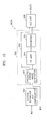
- FIG. 16 is a block diagram of a preferred embodiment 302A of the decoder 302 of FIG. 14, including a VLD unit 350, an inverse quantizer 352, an IOT unit 354, a first MC error image recovery unit 356, and a motion picture recovery unit 358.
- the decoder 302A of FIG. 16 performs step 12A of FIG. 5.
- the VLD unit 350 receives the result of VLC via an input node IN4 and performs VLD on the result of VLC.
- the VLD unit 350 outputs a result 360, obtained by decoding first and second direction information of the results of VLD, to the first MC error image recovery unit 356.
- the inverse quantizer 352 inverse-quantizes the results of VLD input from the VLD unit 350 and outputs the inverse quantization results to the IOT unit 354.
- the IOT unit 354 performs IOT on the inverse quantization results input from the inverse quantizer 352 and outputs the result of IOT as a recovered predicted error image to the first MC error image recovery unit 356.
- the first MC error image recovery unit 356 recovers an MC error image from the recovered predicted error image input from the IOT unit 354 and outputs the recovered MC error image to the motion picture recovery unit 358.
- the motion picture recovery unit 358 recovers a digital motion picture from the recovered MC error image input from the first MC error image recovery unit 356 and outputs the recovery result via an output node OUT3.
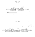
- FIG. 17 is a block diagram of the coder 300 of FIG. 14, or the predicted error image generator 322 of FIG. 15, according to a preferred embodiment of the present invention, including a block determiner 380 and an error predictor 382.
- the block determiner 380 and the error predictor 382 of FIG. 17 perform steps 70 and 72 of FIG. 6, respectively.
- the block determiner 380 determines whether each of MBs of an MC error image input via an input node IN5 is divided into horizontal or vertical blocks and outputs the determination result to the error predictor 382.
- the error predictor 382 predicts an MC error of a current block using a previous block neighboring by a unit pixel distance to the current block in response to the determination result of the block determiner 380, and outputs a predicted error image consisting of predicted MC errors of blocks via an output node OUT4.
- FIG. 18 is a block diagram of a preferred embodiment of 380A of the block determiner 380 of FIG. 17, including a sum calculator 400, a comparator 402, and an information output unit 404.
- the block determiner 380A of FIG. 18 executes step 70A of FIG. 8.
- the sum calculator 400 performs step 140 of FIG. 8.
- the sum calculator 400 sums absolute values of differences between luminance error values of horizontally neighboring pixels in an MB input via an input node IN7 to calculate a first sum S1, as in Equation 1 above.
- the sum calculator 400 sums absolute values of differences between luminance error values of vertically neighboring pixels in the MB input via the input node IN7 to calculate a second sum S2, as in Equation 2 above.
- the comparator 402 compares the first and second sums S1 and S2 input from the sum calculator 400 and outputs the comparison result to the information output unit 404.
- the information output unit 404 determines whether the MB is divided into horizontal or vertical blocks in response to the comparison result of the comparator 402 and outputs information indicating the determination result to the error predictor 382 via an output node OUT5.
- FIG. 19 is a block diagram of a preferred embodiment 382A of the error predictor 382 of FIG. 17, according to a preferred embodiment of the present invention, including a reference value generator 410 and an error operator 412.
- the error predictor 382A of FIG. 19 performs step 72A of FIG. 10.
- the reference value generator 410 may include only an analyzer 424. According to another aspect of the present invention, when step 72 includes steps 170, 172, and 174 of FIG. 10, the reference value generator 410 may include a grouping unit 420 and the analyzer 424.
- the reference value generator 410 generates a reference value of each of pixels in a current block input via an input node IN8 from locally recovered luminance error values of pixels in a previous block input via an input node IN9, and outputs the generated reference value to the error operator 412.
- the grouping unit 420 classifies the pixels in the current block input via the input node IN8 into a predetermined number of groups as shown in FIGS. 11 B through 11E, and outputs information on the resulting groups to the analyzer 422.
- the analyzer 424 analyzes the locally recovered luminance error values of the pixels in the previous block input via the input node IN9 in a predetermined direction to generate the reference value, and outputs the generated reference value to the error operator 412.
- the analyzer 424 analyzes the locally recovered luminance error values of the pixels in the previous block input via the input node IN9 in a predetermined direction, equally applied to each group of pixels, to generate the reference value, and outputs the generated reference value to the error operator 412. For example, the analyzer 424 determines from the resulting groups input from the grouping unit 420 whether pixels whose reference values are to be calculated belong to the same group, and calculates reference values of pixels belonging to the same group in the same predetermined direction as previously described.
- the error operator 412 subtracts the reference value input from the analyzer 424 from a luminance error value of each of the pixels in the current block input via the input node INB, determines the subtraction result as a predicted MC error of each of pixels of each block, and outputs the predicted MC error via an output node OUT6.
- FIG. 20 is a block diagram of the decoder 302 of FIG. 14, or the first MC error image recovery unit 356 of FIG. 16, according to a preferred embodiment of the present invention, including a direction interpreter 440, a reference value recovery unit 442, and an image recovery unit 444.
- the direction interpreter 440, the reference value recovery unit 442, and the image recovery unit 444 of FIG. 20 perform steps 280, 282, and 284 of FIG. 13, respectively.
- the direction interpreter 440 interprets first and second direction information input via an input node IN10, outputs the interpreted first direction information to the image recovery unit 444, and outputs the interpreted second direction information to the reference value recovery unit 442.
- the first and second direction information which is input to the direction interpreter 440 via the input node IN10, may be output from the VLD unit 350 of FIG. 16.
- the reference value recovery unit 442 recovers reference values from the second direction information interpreted by the direction interpreter 440 and recovered luminance error values of pixels in a previous block, and outputs the recovered reference values to the image recovery unit 444.
- the image recovery unit 444 recovers an MC error image from the recovered reference values input from the reference value recovery unit 442, the interpreted first direction information input from the direction interpreter 440, and a recovered predicted error image input via an input node IN11, and outputs the recovery result via an output node OUT7.
- the block diagram of FIG. 20 corresponds to the preferred embodiment of the first MC error image recovery unit 356 of FIG. 16
- the recovered predicted error image which is input to the image recovery unit 444 via the input node IN11, may be output from the IOT unit 354 of FIG. 16.
- power refers to the result of summing squares of predicted MC errors of P ⁇ Q pixels when an MC error image has a size of P ⁇ Q (breadth x length).
- Digital Motion Picture No. Conventional Art Present Invention 1 7249151 4635764 2 778857 642534 3 2723095 1854314 4 2274103 1824485 5 16290092 8592750
- the digital motion picture processing method and apparatus according to the present invention consume less power than the conventional digital motion picture processing method and apparatus. This reduction in power indicates that an amount of data to be coded is reduced and thus coding efficiency is considerably improved by the present invention.
- Table 2 lists power comparison data for the digital motion picture processing method and apparatus according to present invention and the conventional digital motion picture processing method and apparatus when the quantization magnitude is changed from "5" to "15", under the above assumption.
- Digital Motion Picture No. Conventional Art Present Invention 1 7249151 6683817 2 778857 770559 3 2723095 2473157 4 2274103 2188026 5 16290092 11899225
- the digital motion picture processing method and apparatus according to the present invention consumes less power than the conventional digital motion picture processing method and apparatus.
- the digital motion picture processing method and apparatus according to the present invention consumes less power than the conventional digital motion picture processing method and apparatus.
- a method and apparatus for processing a digital motion picture according to the present invention can be easily applied to a method and apparatus for processing a digital motion picture according to the prior art. Also, since an MC error can be efficiently predicted from an MC error image, impulse components of an MC error to be coded can be alleviated to reduce the MC error itself. As a result, data compression efficiency of OT can be improved and correlation among pixels can be lowered. Moreover, even when an MB includes a plurality of different motion components, error around the edge of the MC error image can be relatively reduced, in comparison to the prior art.
Landscapes
- Engineering & Computer Science (AREA)
- Multimedia (AREA)
- Signal Processing (AREA)
- Compression Or Coding Systems Of Tv Signals (AREA)
- Compression, Expansion, Code Conversion, And Decoders (AREA)
Applications Claiming Priority (2)
| Application Number | Priority Date | Filing Date | Title |
|---|---|---|---|
| KR20030086741A KR100601935B1 (ko) | 2003-12-02 | 2003-12-02 | 디지탈 동영상 처리 방법 및 장치 |
| KR2003086741 | 2003-12-02 |
Publications (2)
| Publication Number | Publication Date |
|---|---|
| EP1553781A2 true EP1553781A2 (fr) | 2005-07-13 |
| EP1553781A3 EP1553781A3 (fr) | 2007-09-05 |
Family
ID=34588107
Family Applications (1)
| Application Number | Title | Priority Date | Filing Date |
|---|---|---|---|
| EP20040257499 Withdrawn EP1553781A3 (fr) | 2003-12-02 | 2004-12-02 | Méthode et Procédé pour traitement d'images digitales a mouvement par prédiction de l'erreur de compensation de mouvement utilisant un bloc précédent. |
Country Status (5)
| Country | Link |
|---|---|
| US (1) | US20050135479A1 (fr) |
| EP (1) | EP1553781A3 (fr) |
| JP (1) | JP2005168030A (fr) |
| KR (1) | KR100601935B1 (fr) |
| CN (1) | CN100429946C (fr) |
Families Citing this family (4)
| Publication number | Priority date | Publication date | Assignee | Title |
|---|---|---|---|---|
| TWI348651B (en) * | 2006-06-09 | 2011-09-11 | Via Tech Inc | A system for reducing bandwidth requirements for transferring graphics data and its related method |
| EP2206342A2 (fr) * | 2007-09-10 | 2010-07-14 | Nxp B.V. | Procédé et appareil de destination de mouvement et de compensation de mouvement dans des données d'images vidéo |
| KR102777282B1 (ko) | 2016-05-10 | 2025-03-10 | 삼성전자주식회사 | 영상을 부호화/복호화 하는 방법 및 그 장치 |
| US11195251B1 (en) * | 2020-11-19 | 2021-12-07 | Himax Technologies Limited | Image processing apparatus and method capable of rapidly determining bounding box for motion objects without iteration |
Family Cites Families (7)
| Publication number | Priority date | Publication date | Assignee | Title |
|---|---|---|---|---|
| DE69619002T2 (de) * | 1995-03-10 | 2002-11-21 | Kabushiki Kaisha Toshiba, Kawasaki | Bildkodierungs-/-dekodierungsvorrichtung |
| EP2285119B1 (fr) * | 1997-06-09 | 2015-08-05 | Hitachi, Ltd. | Décodage d'image |
| US5978048A (en) * | 1997-09-25 | 1999-11-02 | Daewoo Electronics Co., Inc. | Method and apparatus for encoding a motion vector based on the number of valid reference motion vectors |
| US6130912A (en) * | 1998-06-09 | 2000-10-10 | Sony Electronics, Inc. | Hierarchical motion estimation process and system using block-matching and integral projection |
| EP1279291B1 (fr) * | 2000-04-14 | 2004-10-06 | Siemens Aktiengesellschaft | Procede et dispositif de mise en memoire et de traitement d'informations d'images successives dans le temps |
| EP1429564A4 (fr) * | 2001-08-28 | 2012-07-25 | Ntt Docomo Inc | Systeme et procede de transmission/codage d'images en mouvement, appareil de codage et appareil de decodage, procedes de decodage et de codage et programme utilisable pour ces derniers |
| JP4015934B2 (ja) * | 2002-04-18 | 2007-11-28 | 株式会社東芝 | 動画像符号化方法及び装置 |
-
2003
- 2003-12-02 KR KR20030086741A patent/KR100601935B1/ko not_active Expired - Fee Related
-
2004
- 2004-12-02 EP EP20040257499 patent/EP1553781A3/fr not_active Withdrawn
- 2004-12-02 US US11/001,643 patent/US20050135479A1/en not_active Abandoned
- 2004-12-02 JP JP2004349836A patent/JP2005168030A/ja active Pending
- 2004-12-02 CN CNB2004100758684A patent/CN100429946C/zh not_active Expired - Fee Related
Also Published As
| Publication number | Publication date |
|---|---|
| US20050135479A1 (en) | 2005-06-23 |
| JP2005168030A (ja) | 2005-06-23 |
| KR20050053129A (ko) | 2005-06-08 |
| KR100601935B1 (ko) | 2006-07-14 |
| EP1553781A3 (fr) | 2007-09-05 |
| CN1652609A (zh) | 2005-08-10 |
| CN100429946C (zh) | 2008-10-29 |
Similar Documents
| Publication | Publication Date | Title |
|---|---|---|
| EP1228645B1 (fr) | Codage adaptatif de champ vectoriel de mouvement | |
| EP2213006B1 (fr) | Procédé et appareil permettant d'effectuer une estimation de mouvement | |
| EP1675403B1 (fr) | Procédé, dispositif et programme de compression codage d'une image animée | |
| US9058659B2 (en) | Methods and apparatuses for encoding/decoding high resolution images | |
| US6711209B1 (en) | Adaptive motion vector field coding | |
| US7869518B2 (en) | Fast motion estimation apparatus and method using block matching algorithm | |
| EP1127458B1 (fr) | Codage video | |
| US20080304760A1 (en) | Method and apparatus for illumination compensation and method and apparatus for encoding and decoding image based on illumination compensation | |
| EP0734177A2 (fr) | Procédé et appareil pour coder/décoder un signal d'image | |
| EP3066832B1 (fr) | Prédiction adaptive des coefficients de blocs vidéo | |
| KR20010033797A (ko) | 스케일 가능한 계층적 움직임 추정을 실행하는 장치 및방법 | |
| JPH04245884A (ja) | 画像の予測符号化方式 | |
| EP0260721B1 (fr) | Procédé et appareil de codage des signaux d'images à mouvements | |
| EP1158806A1 (fr) | Codage de vecteurs de mouvement | |
| JP4494803B2 (ja) | 動き補償に基づいた改善されたノイズ予測方法及びその装置とそれを使用した動画符号化方法及びその装置 | |
| EP1925160A2 (fr) | Prediction spatio/temporelle integree | |
| US8792549B2 (en) | Decoder-derived geometric transformations for motion compensated inter prediction | |
| EP1553781A2 (fr) | Méthode et Procédé pour traitement d'images digitales a mouvement par prédiction de l'erreur de compensation de mouvement utilisant un bloc précédent. | |
| JP2870626B2 (ja) | 画像圧縮装置 | |
| JP2003324732A (ja) | 画像処理装置およびその方法 | |
| JPH06233286A (ja) | フレーム間とフィールド間の処理の切換え方法 | |
| JPH0787582B2 (ja) | 画像符号化伝送装置 | |
| Wu et al. | A fast and quality-preserving method for H. 264 encoding using dynamic SAD maps | |
| JPH07162866A (ja) | 画像符号化装置及び画像復号化装置 | |
| JPH06261308A (ja) | 動画符号化装置 |
Legal Events
| Date | Code | Title | Description |
|---|---|---|---|
| PUAI | Public reference made under article 153(3) epc to a published international application that has entered the european phase |
Free format text: ORIGINAL CODE: 0009012 |
|
| AK | Designated contracting states |
Kind code of ref document: A2 Designated state(s): AT BE BG CH CY CZ DE DK EE ES FI FR GB GR HU IE IS IT LI LT LU MC NL PL PT RO SE SI SK TR |
|
| AX | Request for extension of the european patent |
Extension state: AL BA HR LV MK YU |
|
| PUAL | Search report despatched |
Free format text: ORIGINAL CODE: 0009013 |
|
| AK | Designated contracting states |
Kind code of ref document: A3 Designated state(s): AT BE BG CH CY CZ DE DK EE ES FI FR GB GR HU IE IS IT LI LT LU MC NL PL PT RO SE SI SK TR |
|
| AX | Request for extension of the european patent |
Extension state: AL BA HR LV MK YU |
|
| RIC1 | Information provided on ipc code assigned before grant |
Ipc: H04N 7/26 20060101ALI20070731BHEP Ipc: H04N 7/36 20060101ALI20070731BHEP Ipc: H04N 7/34 20060101AFI20050518BHEP |
|
| AKX | Designation fees paid | ||
| REG | Reference to a national code |
Ref country code: DE Ref legal event code: 8566 |
|
| STAA | Information on the status of an ep patent application or granted ep patent |
Free format text: STATUS: THE APPLICATION IS DEEMED TO BE WITHDRAWN |
|
| 18D | Application deemed to be withdrawn |
Effective date: 20080306 |