EP1553895B1 - Vorrichtung zur verbindung von zwei röhrenförmigen organen - Google Patents
Vorrichtung zur verbindung von zwei röhrenförmigen organen Download PDFInfo
- Publication number
- EP1553895B1 EP1553895B1 EP03771513A EP03771513A EP1553895B1 EP 1553895 B1 EP1553895 B1 EP 1553895B1 EP 03771513 A EP03771513 A EP 03771513A EP 03771513 A EP03771513 A EP 03771513A EP 1553895 B1 EP1553895 B1 EP 1553895B1
- Authority
- EP
- European Patent Office
- Prior art keywords
- organ
- radially
- aperture
- gripping parts
- external
- Prior art date
- Legal status (The legal status is an assumption and is not a legal conclusion. Google has not performed a legal analysis and makes no representation as to the accuracy of the status listed.)
- Expired - Lifetime
Links
- 210000000056 organ Anatomy 0.000 title claims abstract description 101
- 210000004204 blood vessel Anatomy 0.000 claims description 8
- 239000012530 fluid Substances 0.000 claims description 8
- 238000003780 insertion Methods 0.000 claims description 6
- 230000037431 insertion Effects 0.000 claims description 6
- 238000004891 communication Methods 0.000 claims description 2
- 230000001154 acute effect Effects 0.000 claims 1
- 238000000034 method Methods 0.000 abstract description 13
- 230000003872 anastomosis Effects 0.000 description 11
- 239000000853 adhesive Substances 0.000 description 6
- 230000001070 adhesive effect Effects 0.000 description 6
- 210000000078 claw Anatomy 0.000 description 4
- 239000011324 bead Substances 0.000 description 3
- 238000002324 minimally invasive surgery Methods 0.000 description 3
- 235000004443 Ricinus communis Nutrition 0.000 description 2
- 230000004323 axial length Effects 0.000 description 2
- 238000005452 bending Methods 0.000 description 2
- 206010020751 Hypersensitivity Diseases 0.000 description 1
- 238000009825 accumulation Methods 0.000 description 1
- 208000026935 allergic disease Diseases 0.000 description 1
- 229910045601 alloy Inorganic materials 0.000 description 1
- 239000000956 alloy Substances 0.000 description 1
- 230000015572 biosynthetic process Effects 0.000 description 1
- 239000008280 blood Substances 0.000 description 1
- 210000004369 blood Anatomy 0.000 description 1
- 238000013130 cardiovascular surgery Methods 0.000 description 1
- 210000004351 coronary vessel Anatomy 0.000 description 1
- 238000011161 development Methods 0.000 description 1
- 230000018109 developmental process Effects 0.000 description 1
- 230000009610 hypersensitivity Effects 0.000 description 1
- 238000012977 invasive surgical procedure Methods 0.000 description 1
- 239000000463 material Substances 0.000 description 1
- 239000002245 particle Substances 0.000 description 1
- 230000002093 peripheral effect Effects 0.000 description 1
- 238000007789 sealing Methods 0.000 description 1
- 238000011272 standard treatment Methods 0.000 description 1
- 210000000115 thoracic cavity Anatomy 0.000 description 1
- 230000003966 vascular damage Effects 0.000 description 1
- 238000007631 vascular surgery Methods 0.000 description 1
Images




Classifications
-
- A—HUMAN NECESSITIES
- A61—MEDICAL OR VETERINARY SCIENCE; HYGIENE
- A61F—FILTERS IMPLANTABLE INTO BLOOD VESSELS; PROSTHESES; DEVICES PROVIDING PATENCY TO, OR PREVENTING COLLAPSING OF, TUBULAR STRUCTURES OF THE BODY, e.g. STENTS; ORTHOPAEDIC, NURSING OR CONTRACEPTIVE DEVICES; FOMENTATION; TREATMENT OR PROTECTION OF EYES OR EARS; BANDAGES, DRESSINGS OR ABSORBENT PADS; FIRST-AID KITS
- A61F2/00—Filters implantable into blood vessels; Prostheses, i.e. artificial substitutes or replacements for parts of the body; Appliances for connecting them with the body; Devices providing patency to, or preventing collapsing of, tubular structures of the body, e.g. stents
- A61F2/02—Prostheses implantable into the body
- A61F2/04—Hollow or tubular parts of organs, e.g. bladders, tracheae, bronchi or bile ducts
- A61F2/06—Blood vessels
- A61F2/064—Blood vessels with special features to facilitate anastomotic coupling
-
- A—HUMAN NECESSITIES
- A61—MEDICAL OR VETERINARY SCIENCE; HYGIENE
- A61B—DIAGNOSIS; SURGERY; IDENTIFICATION
- A61B17/00—Surgical instruments, devices or methods
- A61B17/064—Surgical staples, i.e. penetrating the tissue
- A61B17/0644—Surgical staples, i.e. penetrating the tissue penetrating the tissue, deformable to closed position
-
- A—HUMAN NECESSITIES
- A61—MEDICAL OR VETERINARY SCIENCE; HYGIENE
- A61B—DIAGNOSIS; SURGERY; IDENTIFICATION
- A61B17/00—Surgical instruments, devices or methods
- A61B17/11—Surgical instruments, devices or methods for performing anastomosis; Buttons for anastomosis
-
- A—HUMAN NECESSITIES
- A61—MEDICAL OR VETERINARY SCIENCE; HYGIENE
- A61F—FILTERS IMPLANTABLE INTO BLOOD VESSELS; PROSTHESES; DEVICES PROVIDING PATENCY TO, OR PREVENTING COLLAPSING OF, TUBULAR STRUCTURES OF THE BODY, e.g. STENTS; ORTHOPAEDIC, NURSING OR CONTRACEPTIVE DEVICES; FOMENTATION; TREATMENT OR PROTECTION OF EYES OR EARS; BANDAGES, DRESSINGS OR ABSORBENT PADS; FIRST-AID KITS
- A61F2/00—Filters implantable into blood vessels; Prostheses, i.e. artificial substitutes or replacements for parts of the body; Appliances for connecting them with the body; Devices providing patency to, or preventing collapsing of, tubular structures of the body, e.g. stents
- A61F2/02—Prostheses implantable into the body
- A61F2/04—Hollow or tubular parts of organs, e.g. bladders, tracheae, bronchi or bile ducts
- A61F2/06—Blood vessels
- A61F2002/061—Blood vessels provided with means for allowing access to secondary lumens
-
- A—HUMAN NECESSITIES
- A61—MEDICAL OR VETERINARY SCIENCE; HYGIENE
- A61F—FILTERS IMPLANTABLE INTO BLOOD VESSELS; PROSTHESES; DEVICES PROVIDING PATENCY TO, OR PREVENTING COLLAPSING OF, TUBULAR STRUCTURES OF THE BODY, e.g. STENTS; ORTHOPAEDIC, NURSING OR CONTRACEPTIVE DEVICES; FOMENTATION; TREATMENT OR PROTECTION OF EYES OR EARS; BANDAGES, DRESSINGS OR ABSORBENT PADS; FIRST-AID KITS
- A61F2/00—Filters implantable into blood vessels; Prostheses, i.e. artificial substitutes or replacements for parts of the body; Appliances for connecting them with the body; Devices providing patency to, or preventing collapsing of, tubular structures of the body, e.g. stents
- A61F2/82—Devices providing patency to, or preventing collapsing of, tubular structures of the body, e.g. stents
- A61F2002/821—Ostial stents
Definitions
- the invention relates to a device for interconnection of and fluid communication between two tubular organs via an opening in an end of an end portion of a first organ and an aperture in a side wall of a second organ.
- the device GraftConnectorTM (WO 01/13820 (Solem)) comprises a Stents shape for securing the inlet branch to the outlet branch internally in a cavity when performing an anastomosis.
- Stents shape for securing the inlet branch to the outlet branch internally in a cavity when performing an anastomosis.
- the object of the invention is to provide a device for such an anastomosis which is not encumbered by the above-mentioned drawbacks.
- the directional indication "forwards" should be understood to refer to the direction towards the edge of the pages of the drawings facing the reader, this direction on the drawing corresponding to the direction in which components of the device according to the invention are moved when the components are joined together. Portions of the components and associated objects are similarly indicated. Furthermore, corresponding components of the various embodiments of the invention will be indicated by the same reference numerals.
- the device according to the invention comprises a first or internal element 1 and a second or external element 2.
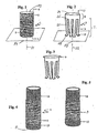
- Fig. 1 illustrates a first embodiment of the first or internal element 1.
- This element preferably is in the form of a straight, thin-walled, cylindrical sleeve with a circular cross section.
- the element 1 has a longitudinal axis 31, a front end portion 3, a front end or end edge 4, a rear end portion 5, a rear end or end edge 6 and a first through-going passage 32.
- the inner diameter of the internal element 1 is adapted to the outer diameter of a tubular first organ 14 such as a blood vessel.
- a severed organ 14 with a free end portion 15 with an end edge 8 can therefore be passed through the element 1 until the end portion 15 protrudes from the element 1 at the element's front end 4.
- the end portion 15 can then be everted or folded round the front end 4 of the element 1 and caused to extend backwards along the outside of the element's front end portion 3, as illustrated in fig. 5.
- the element's front end 4 may be rounded, and to prevent the end portion 15 from being moved back, the front end 4 may be rough.
- Fig. 2 illustrates a first embodiment of the second or external element 2 of the device.
- the external element 2 is similarly provided round a longitudinal axis 33 and has a through-going, second passage 34.
- the eXternal element 2 has a rear, thin-walled, sleeve-shaped end portion or receiving portion 9 with a rear end or edge 10 and a front end or end area 35.
- the cross section of the receiving portion 9 of the external element 2 is preferably circular and is adapted to the cross section of the internal element 1 in such a manner that the internal element 1 with the everted blood vessel 14 can be inserted into this receiving portion 9.
- the internal diameter of the external element 2 hereby corresponds to the external diameter of the internal element 1 plus the double wall thickness of the first organ 14.
- a front end portion 7 comprising a number of elongated, first fingers 11 extending or pointing away from the receiving portion 9 and arranged at intervals along the periphery of the receiving portion 9.
- the fingers 11 comprise a main portion 37, in front of which are connected gripping claws or parts 12.
- the main portions 37 hereby extend forwards along and simultaneously radially towards the longitudinal axis 33, thereby forming a small angle with it when they are not influenced by external forces, i.e. when they are relaxed.
- the gripping claws or parts 12 are bent at an angle relative to the main portion 37 and extend approximately radially away from the longitudinal axis 33.
- the main portions extend in such a manner that the gripping parts' radially external edges or terminations 38 are located on a closed loop, preferably circular, located on or slightly radially within an axial extension of the receiving portion 9 of the external element 2.
- the fingers' main portions 37 may be bent elastically radially outwards in the axial plane which comprises the longitudinal axis 33 to a position wherein the main portion 37 extends substantially axially and the gripping parts 12 extend substantially across the longitudinal axis 33 in this embodiment of the internal element 1.
- Fig. 3 illustrates a second embodiment of the external element 2, where the receiving portion 9 is flared rearwards.
- the end portion may have a corresponding, radially internal bevelled edge.
- the first organ 14 is initially passed through the internal element 1 from the rear end 6 of the element 1 and out through the front end 4 of the element 1 until the end portion 15 of the organ 14 protrudes through this front end 4, whereupon the organ's end portion 15 is everted round the second end 4 as mentioned above.
- the aperture 17 need not be made by forming a circular aperture, but that the aperture may be made, e.g. by cutting a single axial incision or two intersecting incisions in the second organ 16, the gripping parts 12 being inserted in the aperture by bending aside edge portions or edge flaps of the aperture, with the result that the aperture becomes approximately circular.
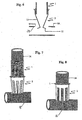
- one option is to insert the gripping parts 12 of the external element 2 in the aperture 17, whereupon the front end portion 3 of the internal element 1 carrying the everted portion 15 of the first organ 14 is inserted in the external element 2 in the forward direction and via its rear end portion 9.
- the gripping parts 12 are pushed radially and preferably elastically outwards and caused to overlap axially with and abut against or engage with an edge portion 39 of the aperture 17 on the inside of the second organ 16.
- the gripping parts 12 are thereby locked, and in this locked position thereby prevent the external element 2 from being retracted from the aperture 17.
- the front end portion 3 of the internal element 1 carrying the everted portion 15 of the first organ 14 can be only partially inserted in the external element 2 in the forward direction and via its rear end portion 9, thus enabling the two elements 1, 2 to be handled as an assembly, but without the gripping parts 12 being pushed radially outwards.
- This assembly can then be moved towards the second organ 16 with only one hand, while the gripping parts 12 of the external element 2 are inserted in the aperture 17, whereupon the internal element 2 is pushed completely into the external elenient, with the result that the gripping parts 12 are pushed radially outwards and caused to overlap axially with and abut against or engage with the edge portion 39 of the aperture 17 on the inside of the second organ 16.
- an adhesive may be applied to the location for the interconnection of the organs as illustrated in fig. 9, the adhesive simultaneously providing a seal between the organs and an interconnection of the organs and possibly the elements.
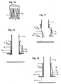
- Fig. 10 illustrates that a fluid 40, such as blood, can flow through the first organ 14, via the elements 1 and 2, into the external element 2, where the fluid can be caused to flow in a desired direction due to the fact that in a portion of the second organ 16, e.g. before the insertion of the external element 2, a sealing plug 41 has been inserted.
- a fluid 40 such as blood
- Fig. 11 illustrates a third embodiment of the external element, this element having a flared, rear end portion 9.
- Fig. 12 illustrates a fourth embodiment of the external element 2, where the rear end portion is cylindrical and may have a bevelled edge.
- Both these last-mentioned embodiments of element 2 have first fingers 11 as described above in connection with the first and second embodiments of the external element 2.
- second fingers 13 are provided along the front edge of the first end portion 9 and between adjaceiit, first fingers 11.
- a main portion 42 of the second fingers 13 extends axially and has at its front end support hooks or support parts 43 which are angled or bent at an angle relative to the main portion 42.
- the support parts 43 thereby remain located radially outside an axial extension of the receiving portion 9 of the external element 2.
- the first organ 14 is initially inserted in the internal element 1 and everted around front edge 4 thereof, and in the second organ 16 an aperture 17 is provided.
- the front portion of the second element 2 is then inserted in the aperture 17 until the gripping parts 12 are located inside the second organ 16 and the support parts 13 have come into abutment against or engagement with the outside of the aperture's edge portion 39.
- the internal element 1 is then inserted in the external element 2 in the same way as that described above, whereby the first fingers 11 are bent radially outwards to abut against the inside of the aperture edge portion 39. If all the fingers are the same length, the aperture edge portion 39 will extend in curves between the gripping parts 12 and the support parts 43. If the second fingers 13 are slightly shorter than the first fingers 11 corresponding to the wall thickness of the second organ 16, the aperture edge portion 39 can extend substantially in one plane.
- An adhesive 18 can then be provided at the point of connection between the organs 14, 16.
- a fifth embodiment of the external element 2 is illustrated, this element 2 resembling the fourth embodiment of the element illustrated in fig. 12.
- the second fingers 13 are curved, or more specifically provided in a convexly radially outward form.
- the axial length of the main portion 42 of the second fingers 13 may be slightly larger than the length of the main portion 37 of the first fingers 11.
- the support parts 43 may already come into abutment against the outside of the edge portion 39 even before the gripping parts 12 have been moved past the aperture edge portion 39 of the second organ 16.
- the second organ 16 can exert a force against the support parts 43, with the result that the main portion 42 of the second fingers 13 becomes even more elastically curved to such an extent that the gripping parts 12 can be moved into the second organ 16 and past the aperture edge portion 39.
- the first fingers 11 are pushed outwards and on account of the extra curve of the second fingers 13, it is ensured that the gripping parts are located at a distance from the aperture edge portion 39. If the elements 1, 2 are subsequently relaxed, the main portions 42 of the second legs 13 will attempt to straighten out, thereby pulling the gripping portions 12 into abutment against or engagement with the inside of the aperture edge portion 39. The aperture edge portion 39 will thereby be securely held between the gripping parts 12 and the support parts 43.
- Fig. 20 illustrates a second embodiment of the internal element 1, where it is inserted, e.g., in an external element 2 of the first embodiment.
- a circumferential shoulder or abutment surface 44 against which the rear edge 10 of the external element 2 can come into abutment when the internal element 1 has been completely inserted in the external element 2.
- a correct relative position of the elements 1, 2 is thereby ensured when they have been mounted for an interconnection of two organs 14, 16.
- the circumferential shoulder 44 may be obtained by the front portion 3 of the internal element 1 having a smaller outer diameter than the rear portion 5 of the element.
- Fig. 22 illustrates a fourth embodiment of the internal element 1, where this element is perforated.
- the weight of the internal element can thereby be reduced.
- the adhesive 18 can be applied to the external surface of the first organ 14 via the perforation, thus effecting adhesion of the first organ 14 to the internal element 1.
- the external element 2 may also include a perforation.
- Fig. 23 illustrates a fifth embodiment of the internal element 1 comprising an internal portion 45 (fig. 26) with a shape corresponding to the shape of, e.g., the internal element 1 according to fig. 1, and a cylindrical, thin-walled, external portion or casing 13a.
- a rear edge 47 of the casing 13a is secured to a radially opposing rear edge 48 of the internal portion 45, the casing 13a and the internal portion 45 being coaxial and defining an annulus 46.
- a slot 13b extending from a front end 49 of the casing 13a for a distance towards the casing's 13a rear end 47.
- Fig. 24 illustrates a sixth embodiment of the external element 2 which is arranged to cooperate with the internal element according to fig. 23, and which resembles the fifth embodiment of this element.
- the receiving portion 9 of the element 2 has an outwardly projecting pin or guide pin 13d, whose width considered tangentially relative to the receiving portion 9 is slightly less than the width of the slot 13b.
- the pin 13d When inserting the internal portion 45 in the external element 2 and inserting the external element 2 into the annulus 46, the pin 13d can be moved into the slot 13b, thus ensuring a correct, relative angular position of the elements 1, 2. Furthermore, the casing 13a can come into abutment against the outside of the curved fingers 13.
- the first element of the device according to the invention may comprise a casing that is not provided with a slot.
- Figures 27-29 illustrate this process of joining together these elements 1 and 2 of the fifth and the sixth embodiment respectively.
- the internal portion 45 of the internal element 1 has been inserted in the receiving portion 9 of the external element 2.
- the receiving portion 9 of the external element 2 has been partially inserted in the annulus 46 between the casing 13a and the internal portion 45 of the internal element 1.
- the external element 2 has been completely inserted in the annulus 46 and the second fingers 13 have been straightened out and locked in this position in the annulus 46.
- the pin 13d can come into abutment against the bottom of the slot 13b.
- the rear end of the external element 2 can come into abutment against the internal element 1 at the rear boundary of the annulus 46.
- Fig. 30 illustrates a seventh embodiment of the external element 2 with alternate straight and curved fingers and with a flared rear portion 9.
- the main portion of at least two fingers, e.g. the straight fingers 11, has a radially outwardly projecting projection or shoulder 13f (see figs. 30-32) which is preferably located near the axial location where the curved fingers' main portions are bent outwards to the greatest extent.
- the element also comprises a ring or locking collar 13e, whose inner diameter is only slightly larger than the outer diameter of the receiving portion 9, and which is arranged axially movably relative to the receiving portion 9 and the fingers 11, 13. The axial movement backwards and forwards, however, is restricted by the locking collar 13e and the shoulders 13f respectively.
- the locking collar 13e When using the device with an external element 2 of this type, the locking collar 13e is initially mounted radially outside the receiving portion 9 of the internal element 1 and the external element 2 is inserted in an aperture in a second organ 16 (see fig. 33).
- the internal element 1 that carries an end portion of a first organ 14 is then inserted in an external element 2 for bending out the first, straight fingers until their gripping claws or parts 12 overlap the aperture edge portion 39 (see fig. 34).
- the locking collar 13e is then moved forwards, and when it meets the curved main portions 42, they are straightened out (see fig. 35).
- the locking collar 13e thus locks the main portions 42 in the straightened position.
- the axial length of the curved fingers 13 thereby increases and the gripping parts 12 are pulled into abutment against the inside of the second organ 16, with the result that this organ's aperture edge portion 39 is secured between the gripping parts 12 and the support parts 43.
- Fig. 36 illustrates the use of two devices according to the invention, where two end portions of a first organ are connected to respective side portions of two second organs by means of the devices.
- the two second organs may hereby have different diameters.
- Such an interconnection of two second organs 16 may be called a side-to-side connection.
- Fig. 37 is a perspective view of a sixth embodiment of the internal element 1, where the front end edge 4 is located in a first plane P1 that forms a minimal angle ⁇ with the element's longitudinal axis 31.
- Fig. 38 is a perspective view of an eighth embodiment of an external element 2 which is arranged to cooperate with the internal element 1 according to fig. 37, and whose gripping claws are located in a second plane P2 that forms the same angle ⁇ with the external element's longitudinal axis 33.
- the first organ should preferably be severed so that its front end 4 extends slantingly at an angle ⁇ relative to the organ's longitudinal axis. If the cross section of the elements is circular, an elliptical aperture 17 should be cut in the second organ 2.
- the internal element 1 may preferably comprise a casing with a slot 13b and the external element 2 may comprise a pin 13d as illustrated in figs. 23 and 24 respectively in order to obtain a correct relative angular position for the elements when they are joined.
- the elements must have a suitable, elliptical cross section, in which case there is no need for a casing with a slot and an external element with a corresponding pin for a correct relative positioning of the elements, since it is only necessary to ensure that the elements' slanting ends extend substantially in parallel.
- a connection is illustrated of two end portions of a first organ 1 with respective side portions of end areas of two second organs 2 by means of the elements according to figs. 37 and 38.
- An approximate end-to-end connection of the second organs 2 and a flow with little fluid resistance can thereby be achieved.
- the internal element 1 may instead be inserted in the first organ 14.
- the front edge of the organ may also be everted around the element's front edge.
- a disadvantage of this is that a rear edge of the first organ 14 may exert a resistance to the fluid flowing in the organ and any particles or the like that are carried along by the fluid may be collected at the edge. In order to reduce this resistance and accumulation, the rear edge may be bevelled.
- the internal element may also have a flared rear end portion or a bead that contributes to the formation of a corresponding bead on the outside of the first organ 14, where the bead of the first organ may come into abutment in the flared, rear portion of the external element 2 in order to establish the relative axial position of the elements.
- the internal element may have at its front end a tangentially extending bevel edge, wherein the everted portion of the first organ can be placed, thus ensuring that the everted portion does not impede the fluid flow.
- the elements may be made of any kind of suitable material.
- the device according to the invention can be used particularly for interconnection of organs of a body, it will be understood that they can be used in general for interconnection of two tubular objects or organs, generally indicated as organs, provided one organ can be everted as stated above.
- the object according to the invention can be employed together with the object of the applicant's international application PCT/NO99/00093.
Landscapes
- Health & Medical Sciences (AREA)
- Life Sciences & Earth Sciences (AREA)
- Surgery (AREA)
- Veterinary Medicine (AREA)
- Public Health (AREA)
- General Health & Medical Sciences (AREA)
- Engineering & Computer Science (AREA)
- Biomedical Technology (AREA)
- Heart & Thoracic Surgery (AREA)
- Animal Behavior & Ethology (AREA)
- Nuclear Medicine, Radiotherapy & Molecular Imaging (AREA)
- Medical Informatics (AREA)
- Molecular Biology (AREA)
- Vascular Medicine (AREA)
- Transplantation (AREA)
- Oral & Maxillofacial Surgery (AREA)
- Cardiology (AREA)
- Pulmonology (AREA)
- Gastroenterology & Hepatology (AREA)
- Prostheses (AREA)
- Surgical Instruments (AREA)
- Lining Or Joining Of Plastics Or The Like (AREA)
Claims (13)
- Vorrichtung zum Verbinden zweier schlauchförmiger Organe (14, 16), insbesondere Blutgefäße eines Körpers, und zur Ausbildung einer Fluidverbindung zwischen diesen durch eine Öffnung in einem Ende (8) eines Endbereiches (15) eines ersten Organs (14) und einen Durchlass (17) in der Seitenwand eines zweiten Organs (16),
dadurch gekennzeichnet, dass die Vorrichtung umfasst- ein erstes Element (1), das sich entlang einer ersten Längsachse (31) erstreckt und eine axiale durchgehende erste Passage (32) und einen vorderen Endbereich (3) mit einer vorderen Endkante (4) aufweist,- ein zweites Element (2), das sich entlang einer zweiten Längsachse (33) erstreckt und eine axiale durchgehende zweite Passage (34), einen axialen hinteren Endbereich oder Aufnahmebereich (9) und einen axialen vorderen Bereich (7) aufweist, umfassend zumindest zwei gestreckte erste Finger (11), die in Intervallen entlang dem Umfang der zweiten Passage (34) angeordnet sind und umfassend jeweilige Hauptbereiche (37), die sich von dem Aufnahmebereich (9) vorwärts erstrecken, entlang und gleichzeitig in Richtung der zweiten Längsachse (33), und Greifteile (12), die sich von den jeweiligen vorderen Enden der Hauptbereiche (37) erstrecken und fort von der zweiten Längsachse (33), wobei- eine Querdimension zwischen radialen äußeren Abschlussenden (38) der Greifteile (12) kleiner ist als die Querdimension oder der Durchmesser des Aufnahmebereichs (9), wenn die Finger (11) entspannt sind, und- der vordere Endbereich (3) des ersten Elements (1) für ein koaxiales Einsetzen in die zweite Passage (34) angeordnet ist und der vordere Bereich (7) durch den Aufnahmebereich (9) und hierdurch zum Ausüben einer radial auswärts gerichteten Kraft gegen die Hauptbereiche (37), wodurch die Hauptbereiche (37) und die Greifteile (12) radial auswärts bewegt werden, bis die Querdimension zwischen den externen Abschlussenden (38) der Greifteile (12) größer ist als die Querdimension oder der Durchmesser des Aufnahmebereichs (12), wobei die Öffnung (17) auf eine solche Weise geformt wurde, dass sie einen Durchmesser korrespondierend zu dem Durchmesser des Aufnahmebereichs des externen Elementes aufweist. - Vorrichtung gemäß Anspruch 1, dadurch gekennzeichnet, dass das zweite Element (2) zumindest einen zusätzlichen zweiten Finger (13) umfasst, der einen Hauptbereich (32) und einen Unterstützungsbereich (43) umfasst, die so angeordnet sind, dass sie gegen die Außenseite des zweiten Organs (16) anliegen, wenn die Greifteile (12) in die Öffnung (17) eingesetzt sind.
- Vorrichtung gemäß Anspruch 2, dadurch gekennzeichnet, dass der Hauptbereich des zweiten Fingers (13) oder möglicherweise zumindest einer aus einer Reihe zweiter Finger (13) konvex in der radialen Auswärtsrichtung ist.
- Vorrichtung gemäß Anspruch 3, dadurch gekennzeichnet, dass das zweite Element (2) einen ringförmigen Kragen (13e) umfasst, der so angeordnet ist, dass er sich erstreckt um und axial bewegt werden kann entlang dem Aufnahmebereich (9) des zweiten Elements (2), mit einem kleinen Abstand, und entlang des vorderen Bereiches (7).
- Vorrichtung gemäß Anspruch 4, dadurch gekennzeichnet, dass zumindest ein Finger (11, 13) mit einer Schulter (13d) vorgesehen ist, die radial auswärts von der radialen, äußeren Seite des Fingers (11, 13) hervorsteht, und der so angeordnet ist, dass er an dem Kragen (13e) anliegt.
- Vorrichtung gemäß einem der Ansprüche 1 - 5, dadurch gekennzeichnet, dass das erste Element (2) einen zylindrischen, manschettenförmigen, radialen inneren Bereich (45) umfasst und ein manschettenförmiges Gehäuse (13a), das koaxial zu dem,inneren Bereich (45) ist und radial außerhalb dessen angeordnet ist, und dessen hinteres Ende (47) befestigt ist an einem radial gegenüberliegenden hinteren Ende (48) des inneren Bereichs (45), wobei das Gehäuse (13a) und der innere Bereich (45) einen zylindrischen Ring (46) definieren.
- Vorrichtung gemäß Anspruch 6, dadurch gekennzeichnet, dass das Gehäuse (13a) darin mit einem Schlitz (13b) versehen ist, der sich von einem vorderen Ende (49) des Gehäuses (13a) in Richtung des hinteren Endes (47) des Gehäuses (13a) erstreckt, und das zweite Element (2) einen auswärts zeigenden Bolzen (13d) aufweist, der zum Einsetzen in den Schlitz (13b) angeordnet ist, wenn das erste Element (1) in das zweite Element (2) eingesetzt wird.
- Vorrichtung gemäß einem der Ansprüche 1 - 7, dadurch gekennzeichnet, dass auf der Außenseite des ersten Elementes (1) eine Schulter (44) vorgesehen ist, die so angeordnet ist, dass sie an einem damit kooperierenden Bereich (10) des zweiten Elementes (2) während des Einsetzens des ersten Elementes (1) in das zweite Element (2) anliegt, um den Einsetzungsabstand zu beschränken.
- Vorrichtung gemäß einem der Ansprüche 1 - 8, dadurch gekennzeichnet, dass das zweite Element (2) und/oder das erste Element (1) perforiert sind.
- Vorrichtung gemäß einem der Ansprüche 1 - 9, dadurch gekennzeichnet, dass der hintere Bereich (9) des zweiten Elementes (2) gebördelt oder angefast ist.
- Vorrichtung gemäß einem der Ansprüche 1 - 10, dadurch gekennzeichnet, dass die vordere Kante (4) des ersten Elementes (1) in einer ersten Ebene (P1) angeordnet ist, und die Greifteile (12) in einer zweiten Ebene (P2) angeordnet sind, wobei die Ebenen (P1, P2) den gleichen Winkel mit den Längsachsen (31, 33) der jeweiligen Elemente (1, 2) ausformen.
- Vorrichtung gemäß Anspruch 11, dadurch gekennzeichnet, dass der Winkel, der durch die Ebenen (P1, P2) mit der jeweiligen Längsachse (31, 33) geformt ist, bei 90° liegt.
- Vorrichtung gemäß Anspruch 11, dadurch gekennzeichnet, dass der Winkel (α), der durch die Ebenen (P1, P2) mit den jeweiligen Längsachsen geformt ist, ein spitzer ist.
Applications Claiming Priority (3)
| Application Number | Priority Date | Filing Date | Title |
|---|---|---|---|
| NO20023605 | 2002-07-29 | ||
| NO20023605A NO20023605D0 (no) | 2002-07-29 | 2002-07-29 | Fremgangsmåte og innretning til innbyrdes forbindelse av to rörformede organer |
| PCT/NO2003/000258 WO2004010898A1 (en) | 2002-07-29 | 2003-07-25 | Method and device for interconnection of two tubular organs |
Publications (2)
| Publication Number | Publication Date |
|---|---|
| EP1553895A1 EP1553895A1 (de) | 2005-07-20 |
| EP1553895B1 true EP1553895B1 (de) | 2006-06-14 |
Family
ID=19913870
Family Applications (1)
| Application Number | Title | Priority Date | Filing Date |
|---|---|---|---|
| EP03771513A Expired - Lifetime EP1553895B1 (de) | 2002-07-29 | 2003-07-25 | Vorrichtung zur verbindung von zwei röhrenförmigen organen |
Country Status (9)
| Country | Link |
|---|---|
| US (1) | US8545524B2 (de) |
| EP (1) | EP1553895B1 (de) |
| JP (1) | JP2005534374A (de) |
| AT (1) | ATE329551T1 (de) |
| AU (1) | AU2003248517B2 (de) |
| CA (1) | CA2493280A1 (de) |
| DE (1) | DE60306182D1 (de) |
| NO (1) | NO20023605D0 (de) |
| WO (1) | WO2004010898A1 (de) |
Families Citing this family (15)
| Publication number | Priority date | Publication date | Assignee | Title |
|---|---|---|---|---|
| US20050222672A1 (en) * | 2004-04-01 | 2005-10-06 | Cappella, Inc. | Ostial stent |
| US8328797B2 (en) | 2004-12-23 | 2012-12-11 | C. R. Bard, Inc. | Blood vessel transecting and anastomosis |
| US8911491B2 (en) * | 2005-09-02 | 2014-12-16 | Medtronic Vascular, Inc. | Methods and apparatus for treatment of aneurysms adjacent branch arteries including branch artery flow lumen alignment |
| US10004507B2 (en) * | 2007-06-18 | 2018-06-26 | Asfora Ip, Llc | Vascular anastomosis device and method |
| US9504469B2 (en) | 2007-06-18 | 2016-11-29 | Asfora Ip, Llc | Vascular anastomosis device and method |
| US9055946B2 (en) | 2008-11-26 | 2015-06-16 | Phraxis Inc. | Anastomotic connector |
| US8308715B2 (en) * | 2009-11-13 | 2012-11-13 | Circulite, Inc. | Cannula stabilizer |
| WO2011112755A2 (en) * | 2010-03-09 | 2011-09-15 | Solinas Medical Inc. | Self-closing devices and methods for making and using them |
| US8333800B2 (en) * | 2010-04-29 | 2012-12-18 | Medtronic Vascular, Inc. | Mobile external coupling with internal sealing cuff for branch vessel connection |
| IT1401467B1 (it) | 2010-06-25 | 2013-07-26 | Sambusseti | Endoprotesi ortotopica di vescica artificiale |
| JP5054166B2 (ja) * | 2010-07-22 | 2012-10-24 | テルモ株式会社 | 人工血管接合体 |
| US9463269B2 (en) * | 2010-09-10 | 2016-10-11 | W. L. Gore & Associates, Inc. | Anastomotic devices and methods |
| US9597443B2 (en) | 2011-06-15 | 2017-03-21 | Phraxis, Inc. | Anastomotic connector |
| WO2012174389A1 (en) | 2011-06-15 | 2012-12-20 | Phraxis Inc. | Anastomotic connector and system for delivery |
| JP6105722B2 (ja) | 2012-06-15 | 2017-03-29 | フラクシス インコーポレイテッド | 吻合部コネクタを形成する動脈および静脈アンカデバイスおよび送達のためのシステム |
Family Cites Families (35)
| Publication number | Priority date | Publication date | Assignee | Title |
|---|---|---|---|---|
| US522005A (en) * | 1894-06-26 | burke | ||
| US1339620A (en) * | 1918-10-15 | 1920-05-11 | Albert A Hart | Hose-coupling |
| US2211776A (en) * | 1937-08-02 | 1940-08-20 | George W Haury | Resilient coupling for tubing and method for making the same |
| US2537183A (en) * | 1949-03-14 | 1951-01-09 | Bloomer Edward James | Coupling connection |
| US3358357A (en) * | 1963-09-30 | 1967-12-19 | Rheem Mfg Co | Method of securing a plastic collar in the orifice of a vessel |
| US3228713A (en) * | 1964-11-23 | 1966-01-11 | William P Frost | Pressure sealed and locked pipe and hose coupling |
| BE801915A (fr) * | 1973-07-04 | 1974-01-04 | Vnii Khirurgicheskoi Apparatur | Dispositif de repliage d'organes creux et appareil de suture comprenant ce dispositif de repliage |
| DE9005035U1 (de) | 1990-05-03 | 1990-07-05 | W.L. Gore & Associates Gmbh, 8011 Putzbrunn | Vorrichtung zur Verwendung in der Gefäßchirurgie |
| US5403333A (en) * | 1990-08-28 | 1995-04-04 | Robert L. Kaster | Side-to-end vascular anastomotic staple apparatus |
| US5309543A (en) * | 1992-11-23 | 1994-05-03 | Ceramoptec, Inc. | Method of making infrared crystalline fiber and product |
| US5668524A (en) * | 1994-02-09 | 1997-09-16 | Kyocera Corporation | Ceramic resistor and electrostatic chuck having an aluminum nitride crystal phase |
| NL9500147A (nl) * | 1995-01-26 | 1996-09-02 | Industrial Res Bv | Werkwijze voor het uit foliemateriaal vervaardigen van een hulsvormige stent, en stent verkregen onder toepassing van deze werkwijze. |
| FR2737653B1 (fr) * | 1995-08-10 | 1997-09-19 | Braun Celsa Sa | Filtre definitif comportant un orifice pour le passage de dispositifs medicaux et son procede de fabrication |
| JP2720381B2 (ja) * | 1995-10-03 | 1998-03-04 | アドバンス・セラミックス・インターナショナル コーポレーション | 任意の電気抵抗率を有する熱分解窒化ホウ素成形体の製造方法 |
| IL125416A0 (en) | 1996-02-02 | 1999-03-12 | Transvascular Inc | Methods and apparatus for connecting openings formed in adjacent blood vessels or other anatomical structures |
| US5850071A (en) * | 1996-02-16 | 1998-12-15 | Kokusai Electric Co., Ltd. | Substrate heating equipment for use in a semiconductor fabricating apparatus |
| US5716081A (en) * | 1996-03-11 | 1998-02-10 | Automotive Products (Usa), Inc. | Spring clip for quick connect coupling |
| SE514595C2 (sv) | 1999-08-25 | 2001-03-19 | Jan Otto Solem | Transplantatkoppling och införingsanordning för denna |
| US6193734B1 (en) * | 1998-01-23 | 2001-02-27 | Heartport, Inc. | System for performing vascular anastomoses |
| WO2000056228A1 (en) | 1999-03-19 | 2000-09-28 | By-Pass, Inc. | Low profile anastomosis connector |
| WO2001070090A2 (en) * | 2000-03-20 | 2001-09-27 | By-Pass, Inc. | Graft and connector delivery |
| WO1999062415A1 (en) | 1998-05-29 | 1999-12-09 | By-Pass, Inc. | Methods and devices for vascular surgery |
| US6461320B1 (en) * | 1998-08-12 | 2002-10-08 | Cardica, Inc. | Method and system for attaching a graft to a blood vessel |
| NL1010386C2 (nl) * | 1998-10-23 | 2000-04-26 | Eric Berreklouw | Anastomose-inrichting. |
| US6152937A (en) | 1998-11-06 | 2000-11-28 | St. Jude Medical Cardiovascular Group, Inc. | Medical graft connector and methods of making and installing same |
| DE69937255T2 (de) * | 1998-11-20 | 2008-07-03 | Steag RTP Systems, Inc., San Jose | Schnell-aufheiz- und -kühlvorrichtung für halbleiterwafer |
| US6428550B1 (en) * | 1999-05-18 | 2002-08-06 | Cardica, Inc. | Sutureless closure and deployment system for connecting blood vessels |
| WO2000072764A1 (en) | 1999-05-28 | 2000-12-07 | The Board Of Trustees Of The Leland Stanford Junior University | Anastomosis system and methods for use |
| US6702828B2 (en) * | 1999-09-01 | 2004-03-09 | Converge Medical, Inc. | Anastomosis system |
| JP2003513696A (ja) * | 1999-11-05 | 2003-04-15 | オーナックス・メディカル・インコーポレーテッド | 吻合中に複数の縫合を配置する装置および方法 |
| EP1265536A1 (de) | 2000-03-20 | 2002-12-18 | By-Pass, Inc. | Transplatatverabreichungssystem |
| US6765178B2 (en) * | 2000-12-29 | 2004-07-20 | Applied Materials, Inc. | Chamber for uniform substrate heating |
| US6497734B1 (en) * | 2002-01-02 | 2002-12-24 | Novellus Systems, Inc. | Apparatus and method for enhanced degassing of semiconductor wafers for increased throughput |
| US20040074898A1 (en) * | 2002-10-21 | 2004-04-22 | Mariner John T. | Encapsulated graphite heater and process |
| EP1588404A2 (de) * | 2003-01-17 | 2005-10-26 | General Electric Company | Waferhandhabungsvorrichtung |
-
2002
- 2002-07-29 NO NO20023605A patent/NO20023605D0/no unknown
-
2003
- 2003-07-25 WO PCT/NO2003/000258 patent/WO2004010898A1/en not_active Ceased
- 2003-07-25 JP JP2004524405A patent/JP2005534374A/ja active Pending
- 2003-07-25 CA CA002493280A patent/CA2493280A1/en not_active Abandoned
- 2003-07-25 AU AU2003248517A patent/AU2003248517B2/en not_active Ceased
- 2003-07-25 DE DE60306182T patent/DE60306182D1/de not_active Expired - Fee Related
- 2003-07-25 AT AT03771513T patent/ATE329551T1/de not_active IP Right Cessation
- 2003-07-25 US US10/522,815 patent/US8545524B2/en not_active Expired - Fee Related
- 2003-07-25 EP EP03771513A patent/EP1553895B1/de not_active Expired - Lifetime
Also Published As
| Publication number | Publication date |
|---|---|
| ATE329551T1 (de) | 2006-07-15 |
| US20060100648A1 (en) | 2006-05-11 |
| WO2004010898A1 (en) | 2004-02-05 |
| AU2003248517B2 (en) | 2006-02-02 |
| US8545524B2 (en) | 2013-10-01 |
| JP2005534374A (ja) | 2005-11-17 |
| DE60306182D1 (de) | 2006-07-27 |
| NO20023605D0 (no) | 2002-07-29 |
| AU2003248517A1 (en) | 2004-02-16 |
| CA2493280A1 (en) | 2004-02-05 |
| EP1553895A1 (de) | 2005-07-20 |
Similar Documents
| Publication | Publication Date | Title |
|---|---|---|
| EP1553895B1 (de) | Vorrichtung zur verbindung von zwei röhrenförmigen organen | |
| US5456714A (en) | Tubular surgical implant having a locking ring and flange | |
| US6508822B1 (en) | Medical graft assembly | |
| US7172608B2 (en) | Sutureless closure and deployment system for connecting blood vessels | |
| US6666873B1 (en) | Surgical coupler for joining tubular and hollow organs | |
| US7041110B2 (en) | Method and system for attaching a graft to a blood vessel | |
| US6972023B2 (en) | Distal anastomosis system | |
| US7108702B2 (en) | Anastomosis device having at least one frangible member | |
| US6929648B2 (en) | Prosthetic vascular graft connector | |
| US20050171565A1 (en) | Anastomosis system utilizing an access port | |
| US20040133221A1 (en) | Connector assembly for joining a graft vessel to a side of a target vessel | |
| US20020099392A1 (en) | Autoanastomosis device and connection technique | |
| US8162963B2 (en) | Angled anastomosis device, tools and method of using |
Legal Events
| Date | Code | Title | Description |
|---|---|---|---|
| PUAI | Public reference made under article 153(3) epc to a published international application that has entered the european phase |
Free format text: ORIGINAL CODE: 0009012 |
|
| 17P | Request for examination filed |
Effective date: 20050225 |
|
| AK | Designated contracting states |
Kind code of ref document: A1 Designated state(s): AT BE BG CH CY CZ DE DK EE ES FI FR GB GR HU IE IT LI LU MC NL PT RO SE SI SK TR |
|
| AX | Request for extension of the european patent |
Extension state: AL LT LV MK |
|
| DAX | Request for extension of the european patent (deleted) | ||
| GRAP | Despatch of communication of intention to grant a patent |
Free format text: ORIGINAL CODE: EPIDOSNIGR1 |
|
| RTI1 | Title (correction) |
Free format text: DEVICE FOR INTERCONNECTION OF TWO TUBULAR ORGANS |
|
| RIC1 | Information provided on ipc code assigned before grant |
Ipc: A61F 2/06 19850101AFI20051121BHEP Ipc: A61B 17/11 19680901ALI20051121BHEP |
|
| GRAS | Grant fee paid |
Free format text: ORIGINAL CODE: EPIDOSNIGR3 |
|
| GRAA | (expected) grant |
Free format text: ORIGINAL CODE: 0009210 |
|
| AK | Designated contracting states |
Kind code of ref document: B1 Designated state(s): AT BE BG CH CY CZ DE DK EE ES FI FR GB GR HU IE IT LI LU MC NL PT RO SE SI SK TR |
|
| PG25 | Lapsed in a contracting state [announced via postgrant information from national office to epo] |
Ref country code: IT Free format text: LAPSE BECAUSE OF FAILURE TO SUBMIT A TRANSLATION OF THE DESCRIPTION OR TO PAY THE FEE WITHIN THE PRESCRIBED TIME-LIMIT;WARNING: LAPSES OF ITALIAN PATENTS WITH EFFECTIVE DATE BEFORE 2007 MAY HAVE OCCURRED AT ANY TIME BEFORE 2007. THE CORRECT EFFECTIVE DATE MAY BE DIFFERENT FROM THE ONE RECORDED. Effective date: 20060614 Ref country code: SI Free format text: LAPSE BECAUSE OF FAILURE TO SUBMIT A TRANSLATION OF THE DESCRIPTION OR TO PAY THE FEE WITHIN THE PRESCRIBED TIME-LIMIT Effective date: 20060614 Ref country code: FI Free format text: LAPSE BECAUSE OF FAILURE TO SUBMIT A TRANSLATION OF THE DESCRIPTION OR TO PAY THE FEE WITHIN THE PRESCRIBED TIME-LIMIT Effective date: 20060614 Ref country code: AT Free format text: LAPSE BECAUSE OF FAILURE TO SUBMIT A TRANSLATION OF THE DESCRIPTION OR TO PAY THE FEE WITHIN THE PRESCRIBED TIME-LIMIT Effective date: 20060614 Ref country code: RO Free format text: LAPSE BECAUSE OF FAILURE TO SUBMIT A TRANSLATION OF THE DESCRIPTION OR TO PAY THE FEE WITHIN THE PRESCRIBED TIME-LIMIT Effective date: 20060614 Ref country code: CH Free format text: LAPSE BECAUSE OF FAILURE TO SUBMIT A TRANSLATION OF THE DESCRIPTION OR TO PAY THE FEE WITHIN THE PRESCRIBED TIME-LIMIT Effective date: 20060614 Ref country code: CZ Free format text: LAPSE BECAUSE OF FAILURE TO SUBMIT A TRANSLATION OF THE DESCRIPTION OR TO PAY THE FEE WITHIN THE PRESCRIBED TIME-LIMIT Effective date: 20060614 Ref country code: NL Free format text: LAPSE BECAUSE OF FAILURE TO SUBMIT A TRANSLATION OF THE DESCRIPTION OR TO PAY THE FEE WITHIN THE PRESCRIBED TIME-LIMIT Effective date: 20060614 Ref country code: BE Free format text: LAPSE BECAUSE OF FAILURE TO SUBMIT A TRANSLATION OF THE DESCRIPTION OR TO PAY THE FEE WITHIN THE PRESCRIBED TIME-LIMIT Effective date: 20060614 Ref country code: LI Free format text: LAPSE BECAUSE OF FAILURE TO SUBMIT A TRANSLATION OF THE DESCRIPTION OR TO PAY THE FEE WITHIN THE PRESCRIBED TIME-LIMIT Effective date: 20060614 Ref country code: SK Free format text: LAPSE BECAUSE OF FAILURE TO SUBMIT A TRANSLATION OF THE DESCRIPTION OR TO PAY THE FEE WITHIN THE PRESCRIBED TIME-LIMIT Effective date: 20060614 |
|
| REG | Reference to a national code |
Ref country code: GB Ref legal event code: FG4D |
|
| REG | Reference to a national code |
Ref country code: CH Ref legal event code: EP |
|
| REG | Reference to a national code |
Ref country code: IE Ref legal event code: FG4D |
|
| REF | Corresponds to: |
Ref document number: 60306182 Country of ref document: DE Date of ref document: 20060727 Kind code of ref document: P |
|
| PG25 | Lapsed in a contracting state [announced via postgrant information from national office to epo] |
Ref country code: MC Free format text: LAPSE BECAUSE OF NON-PAYMENT OF DUE FEES Effective date: 20060731 |
|
| PG25 | Lapsed in a contracting state [announced via postgrant information from national office to epo] |
Ref country code: SE Free format text: LAPSE BECAUSE OF FAILURE TO SUBMIT A TRANSLATION OF THE DESCRIPTION OR TO PAY THE FEE WITHIN THE PRESCRIBED TIME-LIMIT Effective date: 20060914 Ref country code: DK Free format text: LAPSE BECAUSE OF FAILURE TO SUBMIT A TRANSLATION OF THE DESCRIPTION OR TO PAY THE FEE WITHIN THE PRESCRIBED TIME-LIMIT Effective date: 20060914 |
|
| PG25 | Lapsed in a contracting state [announced via postgrant information from national office to epo] |
Ref country code: ES Free format text: LAPSE BECAUSE OF FAILURE TO SUBMIT A TRANSLATION OF THE DESCRIPTION OR TO PAY THE FEE WITHIN THE PRESCRIBED TIME-LIMIT Effective date: 20060925 |
|
| PG25 | Lapsed in a contracting state [announced via postgrant information from national office to epo] |
Ref country code: PT Free format text: LAPSE BECAUSE OF FAILURE TO SUBMIT A TRANSLATION OF THE DESCRIPTION OR TO PAY THE FEE WITHIN THE PRESCRIBED TIME-LIMIT Effective date: 20061114 |
|
| NLV1 | Nl: lapsed or annulled due to failure to fulfill the requirements of art. 29p and 29m of the patents act | ||
| REG | Reference to a national code |
Ref country code: CH Ref legal event code: PL |
|
| PG25 | Lapsed in a contracting state [announced via postgrant information from national office to epo] |
Ref country code: DE Free format text: LAPSE BECAUSE OF NON-PAYMENT OF DUE FEES Effective date: 20070201 |
|
| PLBE | No opposition filed within time limit |
Free format text: ORIGINAL CODE: 0009261 |
|
| STAA | Information on the status of an ep patent application or granted ep patent |
Free format text: STATUS: NO OPPOSITION FILED WITHIN TIME LIMIT |
|
| EN | Fr: translation not filed | ||
| 26N | No opposition filed |
Effective date: 20070315 |
|
| PG25 | Lapsed in a contracting state [announced via postgrant information from national office to epo] |
Ref country code: FR Free format text: LAPSE BECAUSE OF FAILURE TO SUBMIT A TRANSLATION OF THE DESCRIPTION OR TO PAY THE FEE WITHIN THE PRESCRIBED TIME-LIMIT Effective date: 20070309 Ref country code: GR Free format text: LAPSE BECAUSE OF FAILURE TO SUBMIT A TRANSLATION OF THE DESCRIPTION OR TO PAY THE FEE WITHIN THE PRESCRIBED TIME-LIMIT Effective date: 20060915 |
|
| PG25 | Lapsed in a contracting state [announced via postgrant information from national office to epo] |
Ref country code: BG Free format text: LAPSE BECAUSE OF FAILURE TO SUBMIT A TRANSLATION OF THE DESCRIPTION OR TO PAY THE FEE WITHIN THE PRESCRIBED TIME-LIMIT Effective date: 20060914 Ref country code: EE Free format text: LAPSE BECAUSE OF FAILURE TO SUBMIT A TRANSLATION OF THE DESCRIPTION OR TO PAY THE FEE WITHIN THE PRESCRIBED TIME-LIMIT Effective date: 20060614 |
|
| PG25 | Lapsed in a contracting state [announced via postgrant information from national office to epo] |
Ref country code: TR Free format text: LAPSE BECAUSE OF FAILURE TO SUBMIT A TRANSLATION OF THE DESCRIPTION OR TO PAY THE FEE WITHIN THE PRESCRIBED TIME-LIMIT Effective date: 20060614 Ref country code: LU Free format text: LAPSE BECAUSE OF NON-PAYMENT OF DUE FEES Effective date: 20060725 Ref country code: HU Free format text: LAPSE BECAUSE OF FAILURE TO SUBMIT A TRANSLATION OF THE DESCRIPTION OR TO PAY THE FEE WITHIN THE PRESCRIBED TIME-LIMIT Effective date: 20061215 |
|
| PG25 | Lapsed in a contracting state [announced via postgrant information from national office to epo] |
Ref country code: FR Free format text: LAPSE BECAUSE OF FAILURE TO SUBMIT A TRANSLATION OF THE DESCRIPTION OR TO PAY THE FEE WITHIN THE PRESCRIBED TIME-LIMIT Effective date: 20060614 Ref country code: CY Free format text: LAPSE BECAUSE OF FAILURE TO SUBMIT A TRANSLATION OF THE DESCRIPTION OR TO PAY THE FEE WITHIN THE PRESCRIBED TIME-LIMIT Effective date: 20060614 |
|
| REG | Reference to a national code |
Ref country code: GB Ref legal event code: 732E Free format text: REGISTERED BETWEEN 20130516 AND 20130522 |
|
| PGFP | Annual fee paid to national office [announced via postgrant information from national office to epo] |
Ref country code: IE Payment date: 20190723 Year of fee payment: 17 |
|
| PGFP | Annual fee paid to national office [announced via postgrant information from national office to epo] |
Ref country code: GB Payment date: 20190719 Year of fee payment: 17 |
|
| GBPC | Gb: european patent ceased through non-payment of renewal fee |
Effective date: 20200725 |
|
| PG25 | Lapsed in a contracting state [announced via postgrant information from national office to epo] |
Ref country code: GB Free format text: LAPSE BECAUSE OF NON-PAYMENT OF DUE FEES Effective date: 20200725 |
|
| PG25 | Lapsed in a contracting state [announced via postgrant information from national office to epo] |
Ref country code: IE Free format text: LAPSE BECAUSE OF NON-PAYMENT OF DUE FEES Effective date: 20200725 |