EP1554030B1 - Filtre pour plans d'eau presentant une unite de prefiltration - Google Patents
Filtre pour plans d'eau presentant une unite de prefiltration Download PDFInfo
- Publication number
- EP1554030B1 EP1554030B1 EP03790736A EP03790736A EP1554030B1 EP 1554030 B1 EP1554030 B1 EP 1554030B1 EP 03790736 A EP03790736 A EP 03790736A EP 03790736 A EP03790736 A EP 03790736A EP 1554030 B1 EP1554030 B1 EP 1554030B1
- Authority
- EP
- European Patent Office
- Prior art keywords
- filter
- pond
- filter screen
- outlet
- filter according
- Prior art date
- Legal status (The legal status is an assumption and is not a legal conclusion. Google has not performed a legal analysis and makes no representation as to the accuracy of the status listed.)
- Expired - Lifetime
Links
- 238000001914 filtration Methods 0.000 title abstract 2
- XLYOFNOQVPJJNP-UHFFFAOYSA-N water Substances O XLYOFNOQVPJJNP-UHFFFAOYSA-N 0.000 claims abstract description 49
- 238000011010 flushing procedure Methods 0.000 claims description 21
- 238000004140 cleaning Methods 0.000 claims description 5
- 230000005484 gravity Effects 0.000 claims description 3
- 239000000758 substrate Substances 0.000 claims description 3
- 229910021536 Zeolite Inorganic materials 0.000 claims description 2
- HNPSIPDUKPIQMN-UHFFFAOYSA-N dioxosilane;oxo(oxoalumanyloxy)alumane Chemical compound O=[Si]=O.O=[Al]O[Al]=O HNPSIPDUKPIQMN-UHFFFAOYSA-N 0.000 claims description 2
- 239000010457 zeolite Substances 0.000 claims description 2
- OKTJSMMVPCPJKN-UHFFFAOYSA-N Carbon Chemical compound [C] OKTJSMMVPCPJKN-UHFFFAOYSA-N 0.000 claims 1
- 230000004888 barrier function Effects 0.000 claims 1
- 229910052799 carbon Inorganic materials 0.000 claims 1
- 239000003795 chemical substances by application Substances 0.000 claims 1
- 238000011045 prefiltration Methods 0.000 description 14
- 239000000463 material Substances 0.000 description 10
- QVGXLLKOCUKJST-UHFFFAOYSA-N atomic oxygen Chemical compound [O] QVGXLLKOCUKJST-UHFFFAOYSA-N 0.000 description 1
- 239000003245 coal Substances 0.000 description 1
- 239000012535 impurity Substances 0.000 description 1
- 229910052760 oxygen Inorganic materials 0.000 description 1
- 239000001301 oxygen Substances 0.000 description 1
- 239000002245 particle Substances 0.000 description 1
- 239000008213 purified water Substances 0.000 description 1
- 229910001220 stainless steel Inorganic materials 0.000 description 1
- 239000010935 stainless steel Substances 0.000 description 1
Images

Classifications
-
- A—HUMAN NECESSITIES
- A01—AGRICULTURE; FORESTRY; ANIMAL HUSBANDRY; HUNTING; TRAPPING; FISHING
- A01K—ANIMAL HUSBANDRY; AVICULTURE; APICULTURE; PISCICULTURE; FISHING; REARING OR BREEDING ANIMALS, NOT OTHERWISE PROVIDED FOR; NEW BREEDS OF ANIMALS
- A01K63/00—Receptacles for live fish, e.g. aquaria; Terraria
- A01K63/04—Arrangements for treating water specially adapted to receptacles for live fish
- A01K63/045—Filters for aquaria
-
- C—CHEMISTRY; METALLURGY
- C02—TREATMENT OF WATER, WASTE WATER, SEWAGE, OR SLUDGE
- C02F—TREATMENT OF WATER, WASTE WATER, SEWAGE, OR SLUDGE
- C02F9/00—Multistage treatment of water, waste water or sewage
- C02F9/20—Portable or detachable small-scale multistage treatment devices, e.g. point of use or laboratory water purification systems
-
- B—PERFORMING OPERATIONS; TRANSPORTING
- B01—PHYSICAL OR CHEMICAL PROCESSES OR APPARATUS IN GENERAL
- B01D—SEPARATION
- B01D29/00—Filters with filtering elements stationary during filtration, e.g. pressure or suction filters, not covered by groups B01D24/00 - B01D27/00; Filtering elements therefor
- B01D29/01—Filters with filtering elements stationary during filtration, e.g. pressure or suction filters, not covered by groups B01D24/00 - B01D27/00; Filtering elements therefor with flat filtering elements
-
- B—PERFORMING OPERATIONS; TRANSPORTING
- B01—PHYSICAL OR CHEMICAL PROCESSES OR APPARATUS IN GENERAL
- B01D—SEPARATION
- B01D29/00—Filters with filtering elements stationary during filtration, e.g. pressure or suction filters, not covered by groups B01D24/00 - B01D27/00; Filtering elements therefor
- B01D29/11—Filters with filtering elements stationary during filtration, e.g. pressure or suction filters, not covered by groups B01D24/00 - B01D27/00; Filtering elements therefor with bag, cage, hose, tube, sleeve or like filtering elements
- B01D29/114—Filters with filtering elements stationary during filtration, e.g. pressure or suction filters, not covered by groups B01D24/00 - B01D27/00; Filtering elements therefor with bag, cage, hose, tube, sleeve or like filtering elements arranged for inward flow filtration
-
- B—PERFORMING OPERATIONS; TRANSPORTING
- B01—PHYSICAL OR CHEMICAL PROCESSES OR APPARATUS IN GENERAL
- B01D—SEPARATION
- B01D29/00—Filters with filtering elements stationary during filtration, e.g. pressure or suction filters, not covered by groups B01D24/00 - B01D27/00; Filtering elements therefor
- B01D29/50—Filters with filtering elements stationary during filtration, e.g. pressure or suction filters, not covered by groups B01D24/00 - B01D27/00; Filtering elements therefor with multiple filtering elements, characterised by their mutual disposition
- B01D29/52—Filters with filtering elements stationary during filtration, e.g. pressure or suction filters, not covered by groups B01D24/00 - B01D27/00; Filtering elements therefor with multiple filtering elements, characterised by their mutual disposition in parallel connection
-
- B—PERFORMING OPERATIONS; TRANSPORTING
- B01—PHYSICAL OR CHEMICAL PROCESSES OR APPARATUS IN GENERAL
- B01D—SEPARATION
- B01D29/00—Filters with filtering elements stationary during filtration, e.g. pressure or suction filters, not covered by groups B01D24/00 - B01D27/00; Filtering elements therefor
- B01D29/50—Filters with filtering elements stationary during filtration, e.g. pressure or suction filters, not covered by groups B01D24/00 - B01D27/00; Filtering elements therefor with multiple filtering elements, characterised by their mutual disposition
- B01D29/56—Filters with filtering elements stationary during filtration, e.g. pressure or suction filters, not covered by groups B01D24/00 - B01D27/00; Filtering elements therefor with multiple filtering elements, characterised by their mutual disposition in series connection
-
- B—PERFORMING OPERATIONS; TRANSPORTING
- B01—PHYSICAL OR CHEMICAL PROCESSES OR APPARATUS IN GENERAL
- B01D—SEPARATION
- B01D2201/00—Details relating to filtering apparatus
- B01D2201/04—Supports for the filtering elements
- B01D2201/043—Filter tubes connected to plates
- B01D2201/0438—Filter tubes connected to plates mounted substantially vertically on plates at the lower side of the filter elements
-
- C—CHEMISTRY; METALLURGY
- C02—TREATMENT OF WATER, WASTE WATER, SEWAGE, OR SLUDGE
- C02F—TREATMENT OF WATER, WASTE WATER, SEWAGE, OR SLUDGE
- C02F1/00—Treatment of water, waste water, or sewage
- C02F1/28—Treatment of water, waste water, or sewage by sorption
- C02F1/281—Treatment of water, waste water, or sewage by sorption using inorganic sorbents
-
- C—CHEMISTRY; METALLURGY
- C02—TREATMENT OF WATER, WASTE WATER, SEWAGE, OR SLUDGE
- C02F—TREATMENT OF WATER, WASTE WATER, SEWAGE, OR SLUDGE
- C02F1/00—Treatment of water, waste water, or sewage
- C02F1/28—Treatment of water, waste water, or sewage by sorption
- C02F1/283—Treatment of water, waste water, or sewage by sorption using coal, charred products, or inorganic mixtures containing them
Definitions
- the present invention relates to a pond filter with a housing which is supported on a ground side on a substrate, having a longitudinal axis and a transverse axis and in the housing wall, a water inlet, a channel outlet and a pond outlet are formed, wherein in the Housing in the filter operation, a flow path formed from the water inlet to the pond outlet and in the flow path, a filter device is arranged, which is preceded by a prefilter unit comprising a flat-shaped filter screen.
- Such a pond filter is known from GB 2 371 244 A.
- This pond filter has a filter device with a filter screen, which is arranged cylindrical in a direction perpendicular to a transverse axis and a longitudinal axis.
- such a pond filter is placed on the bottom of a pond and is downstream of a pump that pumps water for cleaning in the pond filter.
- a filter unit is arranged, which collects the suspended in the water to be purified floating material and possibly also performs by adding filter aids a biological cleaning.
- the purified water then exits the pond at a pond outlet.
- a pond filter has a channel outlet through which water emerges when the pond filter is cleaned in the flushing operation.
- the object of the present invention is therefore to provide a pond filter, the filter unit is added less quickly, so that a cleaning in relatively large time intervals is required.
- the filter screen is arranged parallel to the transverse axis and at an angle to the longitudinal axis, such that the filter has a bottom near end and a bottom distal end, and that the incoming water from the inlet water to the bottom end of the Filter screen hits.
- the arrangement of a pre-filter unit has the advantage that suspended particles of a predetermined size, for example of size 100 to 250 microns, can be collected and not get into the actual filter unit.
- the prefilter unit comprises a flat filter screen.
- a flat filter screen can be provided with predetermined filter openings depending on the water to be purified.
- the filter screen is arranged parallel to the transverse axis and at an angle to the longitudinal axis, such that the filter screen has a bottom-near and a bottom-distal end.
- the pre-filter unit has a control device which is arranged between the water inlet and the filter screen in the flow path. In such a control device, the inflowing water can be controlled on the filter screen.
- control means is arranged parallel to the transverse axis and forms a flow chamber having at least one outlet opening above the bottom end of the filter screen such that incoming water impinges on the bottom end of the filter screen and on the sloping filter surface flows towards the bottom end and flows in dependence on gravity through filter openings in the filter screen down into the filter unit.
- a further advantage of the present invention is that the flow chamber has at least one reversing element, which is assigned in each case to an outlet opening. With a reversing element, the flow path of the inflowing water can be concentrated on a portion of the filter screen, whereby the pressure of the inflowing water increases in this area and leads to a flushing action on the filter screen.
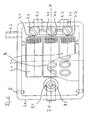
- Fig. 1 is a side view in longitudinal section of a pond filter 1 is shown schematically.
- the pond filter 1 has a housing 3 with a housing wall 3.1 in which a water inlet 3.2, a pond outlet 3.3 and a channel outlet 3.4 is formed.
- a flow path is formed in the housing 3, which runs between the water inlet 3.2 and the pond outlet 3.3.
- a flow path is formed in the housing 3, which runs between the water inlet 3.2 and the channel outlet 3.4.
- the housing 3 has a transverse axis X and a longitudinal axis Y. A direction perpendicular to the longitudinal axis Y and perpendicular to the transverse axis X is referred to as the Z direction.
- the housing 3 has a bottom side 3.5, are formed on the feet 3.6, to support the housing 3 on a substrate.
- the water inlet 3.2 is formed at a bottom distal end of the housing 3.
- the pond outlet 3.3 is formed at a location remote from the housing 3.
- the channel outlet 3.4 is formed at a bottom end of the housing 3.
- a filter unit 5 is arranged in a central region of the housing 3.
- the filter unit 5 comprises a plurality of filter cartridges 5.1, which are arranged at a spatial distance from one another and extend in the Z direction from a holder 5.2.
- the holder 5.2 runs parallel to the transverse axis X and parallel to the longitudinal axis Y.
- Each filter cartridge 5.1 has a central flow channel 5.3 on which is closed to a bottom end and has lateral outlet slots 5.4 around the central flow channel 5.3 around is a porous, permeable and compressible material 5.5 arranged.
- the filter material can be compressed or compressed in the Z direction along the central flow channel 5.3 to express filter material therein in the rinsing operation.
- an additional cartridge 5.6 which contains a filter aid, for example, coal, zeolite, lava, bio cores or the like.
- the additional cartridge 5.6 as arranged in the present embodiment, separated by an intermediate wall 5.7 of the filter cartridges 5.1 be. In other embodiments, however, it is also conceivable to replace individual filter cartridges 5.1 with an additional cartridge 5.6.
- a flow channel is formed, through which the water passed through the filter cartridges can flow in filter operation in the direction of the pond outlet 3.3.
- the water is pressed through an opening 5.8 in the Z direction through the additional cartridge 5.6 to the overhead pond outlet 3.3.
- a prefilter unit 7 is arranged.
- the pre-filter unit 7 extends parallel to the transverse axis X and at an inclination angle to the longitudinal axis Y.
- the arrangement results in that, as can be seen in Fig. 1, the pre-filter unit on the right side in Fig. 1, a bottom-distal end and on the opposite side , in Fig. 1 in the left area, having a bottom-near end.
- the angle of inclination is relatively small.
- the pre-filter unit comprises a filter screen 7.1, which may be made of any material, but is preferably made of stainless steel.
- the filter screen 7.1 has filter openings whose size is arbitrary. In the present embodiment, the filter openings 7.2 a size of 100 to 250 microns.
- the filter screen 7.1 also has a bottom end 7.3 and a bottom near end 7.4.
- Below the filter screen 7.1 is a large-pored plastic mat 7.5 is arranged, through which trickles through the filter screen 7.1 passed through water and can absorb oxygen for nitrification.
- the filter screen 7.1 and the large-pored plastic mat 7.5 are mounted in the prefilter unit 7 in a holder 7.6.
- the prefilter unit 7 comprises a flow chamber 7.8 between the water inlet 3.2 and the filter screen 7.1.
- the water inlet 3.2 in the flow chamber 7.8 can be formed in one or more parts. In Fig. 2, two inlet openings 3.2 are shown in the flow chamber 7.8.
- the flow chamber 7.8 is formed parallel to the transverse axis X and extends substantially across the width of the filter screen 7.1 in the direction of the transverse axis X.
- the filter screen 7.1 is formed in three parts, as can be seen in Fig. 2. In other embodiments, the filter screen 7.1 may also be integrally formed or have more than three parts. The subdivision of the filter screen 7.1 is parallel to the longitudinal axis Y, so that three elongated filter screen parts are formed.
- outlet openings 7.7 are formed, which are each associated with a part of the filter screen 7.1.
- outlet openings 7.1 may be provided, which are then all associated with the one-piece filter screen 7.1.
- at least one outlet opening 7.7 should be assigned to a filter screen part.
- the outlet opening 7.7 is assigned in each case a reversing element 7.9.
- the reversing element 7.9 which may be, for example, a stopcock
- certain outlet openings 7.7 can be closed, thereby concentrating the flow of the inflowing water to certain open outlet openings 7.7.
- two outlet openings 7.7 can be closed, so that the flow of the inflowing water can flow through the third free outlet opening 7.7 onto the corresponding filter screen section 7.1.
- the pressure of the tangentially impinging on the screen part 7.1 water is increased by three times and achieved a flushing action on the surface of the corresponding screen part 7.1.
- the water presses the filter material collected on the filter screen 7.1 towards the bottom-near end 7.4.
- the water itself penetrates as a function of gravity through the filter openings 7.2 and trickles through the plastic mat 7.5 to get into the actual filter unit 5.
- a flushing channel 9 is formed in a Z-direction.
- the flushing channel 9 is in operative connection with the channel outlet 3.4.
- the flushing channel 9 has an inlet opening 9.1.
- a flow obstacle 7.10 is formed between the inlet opening 9.1 and the bottom-near end of the filter screen 7.4.
- the flow obstacle 7.10 is part of the holder 7.6 and extends parallel to the transverse axis X over the entire width of the filter screen 7.1 and blocks the flow path of the incoming water in the direction of the longitudinal axis Y during normal filter operation.
- the strong water flow can overcome the obstacle 7.10 together with the entrained filter material and reach the inlet opening 9.1 in the flushing channel 9.
- the inlet opening 9.1 is closed by a closing element 9.2, such as a stopper. This ensures that even water and filter material, which overcomes the flow obstacle 7.10 in normal filter operation, is collected in a funnel-shaped design of the holder 7.6 and only in rinsing, after removal of the plug 9.2, through the flushing channel 9.1 exit from the channel outlet 3.4 can.
- the holder 7.6 is pivotally mounted on the housing wall 3.1 about a pivot axis S.
- the entire pre-filter unit 7 may be pivotally mounted about the pivot axis S. Due to the pivotable mounting of the holder 7.6, the filter screen 7.1 and the coarse-pored plastic mat 7.5 can be pivoted from a nearly horizontal operating position during the filter operation in a substantially vertical position and vice versa. The vertical position is schematically indicated by a dot / dash line in FIG.
- the filter unit 5 located below the prefilter unit 7 can be easily accessed if it is to be cleaned, for example.
- the operative connection of the flushing channel 9 with the channel outlet 3.4 is detachable, so that the flushing channel 9 can be pulled upwards in the Z direction. This opens the bottom-side flushing channel between the bracket 5.2 and the bottom side 3.5 of the housing 3 to the channel outlet 3.4 out. In this position (not shown) of the flushing channel 9 and the filter unit 5 can be flushed so that the flow path is not in the direction of the pond outlet 3.3 but in the direction of the channel outlet 3.4.
- the rinsing chamber 7.8 of the prefilter unit 7 can also have a rinse water hose connection 7.11.
- the rinsing chamber 7.8 can also be preceded by a UVC light, which already sterilizes the water to be purified.
Landscapes
- Chemical & Material Sciences (AREA)
- Chemical Kinetics & Catalysis (AREA)
- Life Sciences & Earth Sciences (AREA)
- Environmental Sciences (AREA)
- Water Supply & Treatment (AREA)
- Animal Husbandry (AREA)
- Clinical Laboratory Science (AREA)
- Hydrology & Water Resources (AREA)
- Engineering & Computer Science (AREA)
- Environmental & Geological Engineering (AREA)
- Biodiversity & Conservation Biology (AREA)
- Health & Medical Sciences (AREA)
- Organic Chemistry (AREA)
- Marine Sciences & Fisheries (AREA)
- Filtration Of Liquid (AREA)
- Piezo-Electric Or Mechanical Vibrators, Or Delay Or Filter Circuits (AREA)
- Networks Using Active Elements (AREA)
- Water Treatment By Sorption (AREA)
- Separation Using Semi-Permeable Membranes (AREA)
- Filtering Of Dispersed Particles In Gases (AREA)
Claims (18)
- Filtre pour pièce d'eau comprenant un boîtier, qui peut s'appuyer sur un fond par un côté de base, qui présente un axe longitudinal (Y) et un axe transversal (X) et dans la paroi de boîtier duquel sont réalisés une entrée d'eau (3.2), un canal de sortie (3.4) et une sortie de pièce d'eau (3.3), une voie d'écoulement depuis l'entrée d'eau (3.2) à la sortie de pièce d'eau (3.3) étant réalisée dans le boîtier (3) en mode de filtration et un dispositif de filtration (5) étant agencé dans la voie d'écoulement, en amont duquel est placée une unité de préfiltration (7), qui comprend un tamis de filtration (7.1) réalisé de façon plane,
caractérisé en ce que
le tamis de filtration (7.1) est agencé parallèlement à l'axe transversal (X) et sous un certain angle par rapport à l'axe longitudinal (Y), de façon telle que le tamis de filtration (7.1) présente une extrémité plus proche de la base (7.4) et une extrémité plus éloignée de la base (7.3), et en ce que l'eau affluant à partir de l'entrée d'eau (3.2) frappe l'extrémité plus éloignée de la base (7.3) du tamis de filtration (7.1). - Filtre pour pièce d'eau suivant la revendication 1,
caractérisé en ce que
l'unité de préfiltration (7) présente un dispositif de commande (7.8, 7.7, 7.9), qui est agencé dans la voie d'écoulement entre l'entrée d'eau (3.2) et le tamis de filtration (7.1). - Filtre pour pièce d'eau suivant la revendication 2,
caractérisé en ce que
le dispositif de commande (7.8, 7.7, 7.9) est agencé parallèlement à l'axe transversal (X) et forme une chambre d'écoulement (7.8), qui présente au moins un orifice de sortie (7.7) au-dessus de l'extrémité plus éloignée (7.3) de la base du tamis de filtration (7.1), de façon telle que de l'eau affluant frappe l'extrémité plus éloignée du tamis de filtration (7.1) et s'écoule en direction de l'extrémité plus proche de la base (7.4) sur la surface de filtration oblique et coule vers le bas dans l'unité de filtration (5) par des orifices de filtration (7.2) dans le tamis de filtration (7.1) en fonction de la force de gravité. - Filtre pour pièce d'eau suivant la revendication 3,
caractérisé en ce que
la chambre d'écoulement (7.8) présente au moins un élément de renvoi (7.9), qui est adjoint à chaque orifice de sortie (7.7). - Filtre pour pièce d'eau suivant l'une des revendications 1 à 4,
caractérisé en ce que
le tamis de filtration (7.1) est réalisé en plusieurs parties suivant une direction parallèle à l'axe transversal (X). - Filtre pour pièce d'eau suivant la revendication 4 ou 5,
caractérisé en ce que
chaque orifice de sortie (7.7) de la chambre d'écoulement (7.8) est adjoint à une partie du tamis de filtration en plusieurs parties (7.1). - Filtre pour pièce d'eau suivant la revendication 5 ou 6,
caractérisé en ce que
la voie d'écoulement de l'eau affluant peut être changée par l'élément de renvoi (7.9) sur une ou plusieurs parties du tamis de filtration (7.1). - Filtre pour pièce d'eau suivant l'une des revendications 1 à 7,
caractérisé en ce que
un canal à écoulement rapide (9) est relié activement à l'unité de préfiltration (7) derrière l'extrémité plus proche de la base (7.4) du tamis de filtration (7.1) par rapport à l'axe longitudinal (Y). - Filtre pour pièce d'eau suivant la revendication 8,
caractérisé en ce que
le canal à écoulement rapide (9) présente un orifice d'entrée (9.1), qui est fermé en mode de filtration et ouvert en mode de rinçage. - Filtre pour pièce d'eau suivant la revendication 8 ou 9,
caractérisé en ce que
entre le canal à écoulement rapide (9) et le tamis de filtration (7.1) est réalisée une barrière à écoulement parallèlement à l'axe transversal (X), qui est franchissable par l'eau affluant en mode de rinçage. - Filtre pour pièce d'eau suivant la revendication 9 ou 10,
caractérisé en ce que
l'orifice d'entrée (9.1) du canal à écoulement rapide (9) est réalisé sous forme d'entonnoir. - Filtre pour pièce d'eau suivant l'une des revendications précédentes 1 à 11,
caractérisé en ce que
l'unité de préfiltration est réalisée à pivotement. - Filtre pour pièce d'eau suivant la revendication 12,
caractérisé en ce que
l'unité de préfiltration (7) est pivotante autour d'un axe de pivotement (S) parallèlement à l'axe transversal (X). - Filtre pour pièce d'eau suivant la revendication 13,
caractérisé en ce que
l'axe de pivotement (S) est agencé au-dessus du canal à écoulement rapide (9). - Filtre pour pièce d'eau suivant la revendication 14,
caractérisé en ce que
l'unité de préfiltration (7) est pivotante autour de l'axe de pivotement (S) entre une position sensiblement horizontale pour le mode de filtration et une position sensiblement verticale. - Filtre pour pièce d'eau suivant l'une des revendications 8 à 15,
caractérisé en ce que
le canal à écoulement rapide (9) est libérable d'une liaison active avec le canal de sortie (3.4), de façon telle qu'il se forme une voie d'écoulement de l'eau à partir de l'unité de filtration (5) dans le canal de sortie (3.4), afin d'obtenir une action de rinçage pour l'unité de filtration (5). - Filtre pour pièce d'eau suivant l'une des revendications précédentes,
caractérisé en ce que
l'unité de filtration (5) est constituée de plusieurs cartouches de filtration (5.1), qui sont réalisées de façon comprimable à des fins de nettoyage. - Filtre pour pièce d'eau suivant l'une des revendications précédentes,
caractérisé en ce que
l'unité de filtration (5) présente au moins une cartouche d'appoint (5.6), qui contient un moyen de filtration auxiliaire sélectionné à partir du groupe constitué de charbon, zéolithe, lave, noyau biologique.
Applications Claiming Priority (3)
| Application Number | Priority Date | Filing Date | Title |
|---|---|---|---|
| DE10240454A DE10240454B4 (de) | 2002-08-30 | 2002-08-30 | Teichfilter mit Vorfiltereinheit |
| DE10240454 | 2002-08-30 | ||
| PCT/DE2003/002807 WO2004020343A2 (fr) | 2002-08-30 | 2003-08-22 | Filtre pour plans d'eau presentant une unite de prefiltration |
Publications (2)
| Publication Number | Publication Date |
|---|---|
| EP1554030A2 EP1554030A2 (fr) | 2005-07-20 |
| EP1554030B1 true EP1554030B1 (fr) | 2007-04-25 |
Family
ID=31724255
Family Applications (1)
| Application Number | Title | Priority Date | Filing Date |
|---|---|---|---|
| EP03790736A Expired - Lifetime EP1554030B1 (fr) | 2002-08-30 | 2003-08-22 | Filtre pour plans d'eau presentant une unite de prefiltration |
Country Status (9)
| Country | Link |
|---|---|
| US (1) | US7264720B2 (fr) |
| EP (1) | EP1554030B1 (fr) |
| CN (1) | CN1331558C (fr) |
| AT (1) | ATE360466T1 (fr) |
| AU (1) | AU2003266178A1 (fr) |
| CA (1) | CA2497050A1 (fr) |
| DE (2) | DE10240454B4 (fr) |
| ES (1) | ES2282723T3 (fr) |
| WO (1) | WO2004020343A2 (fr) |
Families Citing this family (14)
| Publication number | Priority date | Publication date | Assignee | Title |
|---|---|---|---|---|
| DE10359432A1 (de) * | 2003-12-17 | 2005-07-21 | Reiner Seitz | Filterbecken mit mehreren Kammern |
| DE202005011244U1 (de) | 2004-06-10 | 2005-12-15 | Hozelock Ltd., Haddenham, Aylesbury | Pumpeneinheit |
| WO2005123215A1 (fr) * | 2004-06-22 | 2005-12-29 | Oase Gmbh | Filtre de passage avec controle d'encrassement |
| DE102005042457B4 (de) * | 2005-09-06 | 2007-08-02 | Oase Gmbh | Wasserreinigungsgerät für Teiche oder dergleichen Gewässer |
| DE102005042626A1 (de) | 2005-09-07 | 2007-03-15 | Oase Gmbh | Filter für insbesondere Teiche |
| WO2012061906A1 (fr) * | 2010-11-12 | 2012-05-18 | Poolrite Research Pty Ltd | Unité de filtration |
| CN106823509A (zh) * | 2017-04-07 | 2017-06-13 | 河南师范大学 | 一种自清洁鱼缸过滤器 |
| CN108211469A (zh) * | 2018-01-05 | 2018-06-29 | 惠安北酷机械科技有限公司 | 一种糖加工用原料中汁液残渣高效过滤设备 |
| US20200197989A1 (en) * | 2018-12-19 | 2020-06-25 | DPFSource LLC | Flush Station |
| US12041917B2 (en) | 2019-03-04 | 2024-07-23 | Spectrum Brands, Inc. | Aquarium filter arrangement including pre-filter member and methods |
| US20240091680A1 (en) * | 2019-09-30 | 2024-03-21 | Orenco Systems, Inc. | Passive self-cleaning filtration method and apparatus |
| US20220088541A1 (en) * | 2020-09-18 | 2022-03-24 | Pall Corporation | Filter with interconnected hollow elements and method of use |
| CN112279391A (zh) * | 2020-10-14 | 2021-01-29 | 太仓中化环保化工有限公司 | 一种化工污水处理装置 |
| CN114224238B (zh) * | 2022-01-18 | 2023-01-17 | 深圳银星智能集团股份有限公司 | 清洁设备及清洁机器人系统 |
Family Cites Families (15)
| Publication number | Priority date | Publication date | Assignee | Title |
|---|---|---|---|---|
| SE379647B (fr) * | 1970-02-18 | 1975-10-20 | A J Walker | |
| US3884811A (en) * | 1973-01-19 | 1975-05-20 | Vortex Fishery Equipment Ltd | Filter |
| US3957634A (en) * | 1974-05-20 | 1976-05-18 | Orensten Henry E | Filtration means and method |
| GB8323919D0 (en) * | 1983-09-07 | 1983-10-12 | Goodson M G | Water filtration/biological purification system |
| IT1254714B (it) | 1992-01-20 | 1995-10-09 | Filtro percolatore a pressione del tipo impiegato per la rigenerazione dell'acqua di acquari. | |
| US5294335A (en) * | 1993-07-20 | 1994-03-15 | Michael Chiang | Filter device for aquarium tanks or artificial ponds |
| US5407456A (en) * | 1994-01-28 | 1995-04-18 | Tseng; Ching-Chih | Exhaust gas purifying device for vehicles |
| GB2307421A (en) * | 1995-11-16 | 1997-05-28 | Malcolm Graham Goodson | Method and apparatus for water treatment |
| GB9623362D0 (en) * | 1996-11-09 | 1997-01-08 | Goodson Malcolm G | Method and apparatus for water treatment |
| DE19941457A1 (de) * | 1999-08-31 | 2001-03-01 | Thomas Willuweit | Teichfilter |
| GB2367506A (en) * | 2000-08-23 | 2002-04-10 | Roderick Morgan | Pump inlet strainer |
| DE10043595B4 (de) * | 2000-09-01 | 2004-07-08 | Söll Gmbh | Wasserfilter |
| JP2002119458A (ja) * | 2000-10-16 | 2002-04-23 | Matsushita Electric Ind Co Ltd | 食器洗い乾燥機 |
| EP1361913A1 (fr) | 2001-01-18 | 2003-11-19 | Nicholas Jackson | Filtre a eau |
| GB2371244B (en) * | 2001-01-18 | 2004-05-12 | Nicholas Jackson | Water purification system |
-
2002
- 2002-08-30 DE DE10240454A patent/DE10240454B4/de not_active Expired - Lifetime
-
2003
- 2003-08-22 CN CNB038205866A patent/CN1331558C/zh not_active Expired - Fee Related
- 2003-08-22 AU AU2003266178A patent/AU2003266178A1/en not_active Abandoned
- 2003-08-22 DE DE50307146T patent/DE50307146D1/de not_active Expired - Lifetime
- 2003-08-22 CA CA002497050A patent/CA2497050A1/fr not_active Abandoned
- 2003-08-22 US US10/526,056 patent/US7264720B2/en not_active Expired - Fee Related
- 2003-08-22 AT AT03790736T patent/ATE360466T1/de not_active IP Right Cessation
- 2003-08-22 ES ES03790736T patent/ES2282723T3/es not_active Expired - Lifetime
- 2003-08-22 WO PCT/DE2003/002807 patent/WO2004020343A2/fr not_active Ceased
- 2003-08-22 EP EP03790736A patent/EP1554030B1/fr not_active Expired - Lifetime
Also Published As
| Publication number | Publication date |
|---|---|
| WO2004020343B1 (fr) | 2004-06-17 |
| DE10240454A1 (de) | 2004-03-18 |
| CN1700947A (zh) | 2005-11-23 |
| WO2004020343A3 (fr) | 2004-04-29 |
| WO2004020343A2 (fr) | 2004-03-11 |
| AU2003266178A1 (en) | 2004-03-19 |
| DE10240454B4 (de) | 2005-12-22 |
| EP1554030A2 (fr) | 2005-07-20 |
| CN1331558C (zh) | 2007-08-15 |
| US7264720B2 (en) | 2007-09-04 |
| CA2497050A1 (fr) | 2004-03-11 |
| AU2003266178A8 (en) | 2004-03-19 |
| ATE360466T1 (de) | 2007-05-15 |
| ES2282723T3 (es) | 2007-10-16 |
| US20050252842A1 (en) | 2005-11-17 |
| DE50307146D1 (de) | 2007-06-06 |
Similar Documents
| Publication | Publication Date | Title |
|---|---|---|
| DE69419210T3 (de) | Belüfter für Flüssigkeiten | |
| DE19837569B4 (de) | Verfahren zur Reinigung von Filterkerzen eines Kerzenfilters | |
| DE10240454B4 (de) | Teichfilter mit Vorfiltereinheit | |
| DE69415551T2 (de) | Aeroben filteranordnung für aquarien | |
| DE2703610A1 (de) | Zyklonanordnung und verfahren zum beseitigen von verstopfungen bei zyklonanordnungen | |
| DE10303677A1 (de) | Staubsauger | |
| DE1517604C3 (de) | Vorrichtung zur Behandlung des Wassers eines Schwimmbeckens | |
| DE1611158C3 (de) | Filtereinrichtung | |
| DE1436287A1 (de) | Verfahren zum Filtern eines Fluids und Anlage zur Durchfuehrung des Verfahrens | |
| DE2602581A1 (de) | Verfahren und vorrichtung zum regenerieren von druckfiltern | |
| DE69601298T2 (de) | Filtereinrichtung | |
| DE2123683C3 (de) | Filtereinrichtung | |
| EP0732457A2 (fr) | Procédé et dispositif de récupération d'eau usagée | |
| DE112018004424T5 (de) | Austragsverarbeitungseinrichtung für ein Fahrzeugdruckluftbremsenfüllsystem | |
| WO1992001500A1 (fr) | Dispositif de filtration pour matiere thermoplastique | |
| DE19912449C1 (de) | Regenwasserfilter | |
| EP0718022A1 (fr) | Filtre à arêtes pour liquides et gaz | |
| WO2019072896A1 (fr) | Dispositif de conditionnement d'eau | |
| DE69906521T2 (de) | Verfahren und vorrichtung in einer trockenreinigungsmaschine | |
| CH678820A5 (fr) | ||
| WO2001017660A2 (fr) | Systeme de filtrage pour eaux d'etang ou analogue | |
| DE2721505B2 (de) | Filter zur Reinigung von Natur und Abwässern | |
| DE10002397A1 (de) | Absetzfilter | |
| DE69805297T2 (de) | Sinkkasten | |
| EP1760046B1 (fr) | Purificateur d'eau compact pour étangs |
Legal Events
| Date | Code | Title | Description |
|---|---|---|---|
| PUAI | Public reference made under article 153(3) epc to a published international application that has entered the european phase |
Free format text: ORIGINAL CODE: 0009012 |
|
| 17P | Request for examination filed |
Effective date: 20050224 |
|
| AK | Designated contracting states |
Kind code of ref document: A2 Designated state(s): AT BE BG CH CY CZ DE DK EE ES FI FR GB GR HU IE IT LI LU MC NL PT RO SE SI SK TR |
|
| AX | Request for extension of the european patent |
Extension state: AL LT LV MK |
|
| DAX | Request for extension of the european patent (deleted) | ||
| GRAP | Despatch of communication of intention to grant a patent |
Free format text: ORIGINAL CODE: EPIDOSNIGR1 |
|
| GRAS | Grant fee paid |
Free format text: ORIGINAL CODE: EPIDOSNIGR3 |
|
| GRAA | (expected) grant |
Free format text: ORIGINAL CODE: 0009210 |
|
| AK | Designated contracting states |
Kind code of ref document: B1 Designated state(s): AT BE BG CH CY CZ DE DK EE ES FI FR GB GR HU IE IT LI LU MC NL PT RO SE SI SK TR |
|
| PG25 | Lapsed in a contracting state [announced via postgrant information from national office to epo] |
Ref country code: FI Free format text: LAPSE BECAUSE OF FAILURE TO SUBMIT A TRANSLATION OF THE DESCRIPTION OR TO PAY THE FEE WITHIN THE PRESCRIBED TIME-LIMIT Effective date: 20070425 |
|
| REG | Reference to a national code |
Ref country code: GB Ref legal event code: FG4D Free format text: NOT ENGLISH |
|
| GBT | Gb: translation of ep patent filed (gb section 77(6)(a)/1977) |
Effective date: 20070425 |
|
| REG | Reference to a national code |
Ref country code: IE Ref legal event code: FG4D Free format text: LANGUAGE OF EP DOCUMENT: GERMAN |
|
| REG | Reference to a national code |
Ref country code: CH Ref legal event code: EP |
|
| REF | Corresponds to: |
Ref document number: 50307146 Country of ref document: DE Date of ref document: 20070606 Kind code of ref document: P |
|
| PG25 | Lapsed in a contracting state [announced via postgrant information from national office to epo] |
Ref country code: SE Free format text: LAPSE BECAUSE OF FAILURE TO SUBMIT A TRANSLATION OF THE DESCRIPTION OR TO PAY THE FEE WITHIN THE PRESCRIBED TIME-LIMIT Effective date: 20070725 |
|
| ET | Fr: translation filed | ||
| PG25 | Lapsed in a contracting state [announced via postgrant information from national office to epo] |
Ref country code: PT Free format text: LAPSE BECAUSE OF FAILURE TO SUBMIT A TRANSLATION OF THE DESCRIPTION OR TO PAY THE FEE WITHIN THE PRESCRIBED TIME-LIMIT Effective date: 20070925 |
|
| REG | Reference to a national code |
Ref country code: ES Ref legal event code: FG2A Ref document number: 2282723 Country of ref document: ES Kind code of ref document: T3 |
|
| REG | Reference to a national code |
Ref country code: IE Ref legal event code: FD4D |
|
| PG25 | Lapsed in a contracting state [announced via postgrant information from national office to epo] |
Ref country code: SI Free format text: LAPSE BECAUSE OF FAILURE TO SUBMIT A TRANSLATION OF THE DESCRIPTION OR TO PAY THE FEE WITHIN THE PRESCRIBED TIME-LIMIT Effective date: 20070425 Ref country code: IE Free format text: LAPSE BECAUSE OF FAILURE TO SUBMIT A TRANSLATION OF THE DESCRIPTION OR TO PAY THE FEE WITHIN THE PRESCRIBED TIME-LIMIT Effective date: 20070425 Ref country code: BG Free format text: LAPSE BECAUSE OF FAILURE TO SUBMIT A TRANSLATION OF THE DESCRIPTION OR TO PAY THE FEE WITHIN THE PRESCRIBED TIME-LIMIT Effective date: 20070725 Ref country code: DK Free format text: LAPSE BECAUSE OF FAILURE TO SUBMIT A TRANSLATION OF THE DESCRIPTION OR TO PAY THE FEE WITHIN THE PRESCRIBED TIME-LIMIT Effective date: 20070425 Ref country code: CZ Free format text: LAPSE BECAUSE OF FAILURE TO SUBMIT A TRANSLATION OF THE DESCRIPTION OR TO PAY THE FEE WITHIN THE PRESCRIBED TIME-LIMIT Effective date: 20070425 |
|
| PG25 | Lapsed in a contracting state [announced via postgrant information from national office to epo] |
Ref country code: SK Free format text: LAPSE BECAUSE OF FAILURE TO SUBMIT A TRANSLATION OF THE DESCRIPTION OR TO PAY THE FEE WITHIN THE PRESCRIBED TIME-LIMIT Effective date: 20070425 |
|
| PLBE | No opposition filed within time limit |
Free format text: ORIGINAL CODE: 0009261 |
|
| STAA | Information on the status of an ep patent application or granted ep patent |
Free format text: STATUS: NO OPPOSITION FILED WITHIN TIME LIMIT |
|
| 26N | No opposition filed |
Effective date: 20080128 |
|
| REG | Reference to a national code |
Ref country code: CH Ref legal event code: PL |
|
| PG25 | Lapsed in a contracting state [announced via postgrant information from national office to epo] |
Ref country code: CH Free format text: LAPSE BECAUSE OF NON-PAYMENT OF DUE FEES Effective date: 20070831 Ref country code: IT Free format text: LAPSE BECAUSE OF FAILURE TO SUBMIT A TRANSLATION OF THE DESCRIPTION OR TO PAY THE FEE WITHIN THE PRESCRIBED TIME-LIMIT Effective date: 20070425 Ref country code: GR Free format text: LAPSE BECAUSE OF FAILURE TO SUBMIT A TRANSLATION OF THE DESCRIPTION OR TO PAY THE FEE WITHIN THE PRESCRIBED TIME-LIMIT Effective date: 20070726 Ref country code: MC Free format text: LAPSE BECAUSE OF NON-PAYMENT OF DUE FEES Effective date: 20070831 Ref country code: LI Free format text: LAPSE BECAUSE OF NON-PAYMENT OF DUE FEES Effective date: 20070831 |
|
| PG25 | Lapsed in a contracting state [announced via postgrant information from national office to epo] |
Ref country code: RO Free format text: LAPSE BECAUSE OF FAILURE TO SUBMIT A TRANSLATION OF THE DESCRIPTION OR TO PAY THE FEE WITHIN THE PRESCRIBED TIME-LIMIT Effective date: 20070425 |
|
| PG25 | Lapsed in a contracting state [announced via postgrant information from national office to epo] |
Ref country code: EE Free format text: LAPSE BECAUSE OF FAILURE TO SUBMIT A TRANSLATION OF THE DESCRIPTION OR TO PAY THE FEE WITHIN THE PRESCRIBED TIME-LIMIT Effective date: 20070425 |
|
| PGFP | Annual fee paid to national office [announced via postgrant information from national office to epo] |
Ref country code: AT Payment date: 20090219 Year of fee payment: 6 Ref country code: ES Payment date: 20090225 Year of fee payment: 6 |
|
| PGFP | Annual fee paid to national office [announced via postgrant information from national office to epo] |
Ref country code: NL Payment date: 20090223 Year of fee payment: 6 |
|
| PGFP | Annual fee paid to national office [announced via postgrant information from national office to epo] |
Ref country code: GB Payment date: 20090223 Year of fee payment: 6 |
|
| PG25 | Lapsed in a contracting state [announced via postgrant information from national office to epo] |
Ref country code: CY Free format text: LAPSE BECAUSE OF FAILURE TO SUBMIT A TRANSLATION OF THE DESCRIPTION OR TO PAY THE FEE WITHIN THE PRESCRIBED TIME-LIMIT Effective date: 20070425 |
|
| PGFP | Annual fee paid to national office [announced via postgrant information from national office to epo] |
Ref country code: BE Payment date: 20090224 Year of fee payment: 6 |
|
| PG25 | Lapsed in a contracting state [announced via postgrant information from national office to epo] |
Ref country code: LU Free format text: LAPSE BECAUSE OF NON-PAYMENT OF DUE FEES Effective date: 20070822 |
|
| PG25 | Lapsed in a contracting state [announced via postgrant information from national office to epo] |
Ref country code: HU Free format text: LAPSE BECAUSE OF FAILURE TO SUBMIT A TRANSLATION OF THE DESCRIPTION OR TO PAY THE FEE WITHIN THE PRESCRIBED TIME-LIMIT Effective date: 20071026 Ref country code: TR Free format text: LAPSE BECAUSE OF FAILURE TO SUBMIT A TRANSLATION OF THE DESCRIPTION OR TO PAY THE FEE WITHIN THE PRESCRIBED TIME-LIMIT Effective date: 20070425 |
|
| PGFP | Annual fee paid to national office [announced via postgrant information from national office to epo] |
Ref country code: FR Payment date: 20090217 Year of fee payment: 6 |
|
| PGFP | Annual fee paid to national office [announced via postgrant information from national office to epo] |
Ref country code: DE Payment date: 20090928 Year of fee payment: 7 |
|
| BERE | Be: lapsed |
Owner name: OASE G.M.B.H. Effective date: 20090831 |
|
| REG | Reference to a national code |
Ref country code: NL Ref legal event code: V1 Effective date: 20100301 |
|
| GBPC | Gb: european patent ceased through non-payment of renewal fee |
Effective date: 20090822 |
|
| REG | Reference to a national code |
Ref country code: FR Ref legal event code: ST Effective date: 20100430 |
|
| PG25 | Lapsed in a contracting state [announced via postgrant information from national office to epo] |
Ref country code: BE Free format text: LAPSE BECAUSE OF NON-PAYMENT OF DUE FEES Effective date: 20090831 Ref country code: AT Free format text: LAPSE BECAUSE OF NON-PAYMENT OF DUE FEES Effective date: 20090822 |
|
| PG25 | Lapsed in a contracting state [announced via postgrant information from national office to epo] |
Ref country code: FR Free format text: LAPSE BECAUSE OF NON-PAYMENT OF DUE FEES Effective date: 20090831 Ref country code: NL Free format text: LAPSE BECAUSE OF NON-PAYMENT OF DUE FEES Effective date: 20100301 |
|
| REG | Reference to a national code |
Ref country code: ES Ref legal event code: FD2A Effective date: 20090824 |
|
| PG25 | Lapsed in a contracting state [announced via postgrant information from national office to epo] |
Ref country code: GB Free format text: LAPSE BECAUSE OF NON-PAYMENT OF DUE FEES Effective date: 20090822 |
|
| REG | Reference to a national code |
Ref country code: DE Ref legal event code: R119 Ref document number: 50307146 Country of ref document: DE Effective date: 20110301 |
|
| PG25 | Lapsed in a contracting state [announced via postgrant information from national office to epo] |
Ref country code: DE Free format text: LAPSE BECAUSE OF NON-PAYMENT OF DUE FEES Effective date: 20110301 |
|
| PG25 | Lapsed in a contracting state [announced via postgrant information from national office to epo] |
Ref country code: ES Free format text: LAPSE BECAUSE OF NON-PAYMENT OF DUE FEES Effective date: 20090823 |