EP1554151B1 - Véhicule cabriolet comportant un caisson recevant la capote - Google Patents
Véhicule cabriolet comportant un caisson recevant la capote Download PDFInfo
- Publication number
- EP1554151B1 EP1554151B1 EP03775047.8A EP03775047A EP1554151B1 EP 1554151 B1 EP1554151 B1 EP 1554151B1 EP 03775047 A EP03775047 A EP 03775047A EP 1554151 B1 EP1554151 B1 EP 1554151B1
- Authority
- EP
- European Patent Office
- Prior art keywords
- convertible vehicle
- vehicle according
- hinge
- movement
- hood
- Prior art date
- Legal status (The legal status is an assumption and is not a legal conclusion. Google has not performed a legal analysis and makes no representation as to the accuracy of the status listed.)
- Expired - Lifetime
Links
- 230000000903 blocking effect Effects 0.000 claims description 8
- 238000006073 displacement reaction Methods 0.000 claims description 5
- 230000007246 mechanism Effects 0.000 claims description 3
- 230000013011 mating Effects 0.000 claims 1
- 238000000034 method Methods 0.000 description 2
- 230000008569 process Effects 0.000 description 2
- 230000009471 action Effects 0.000 description 1
- 230000004913 activation Effects 0.000 description 1
- 230000000712 assembly Effects 0.000 description 1
- 238000000429 assembly Methods 0.000 description 1
- 230000004888 barrier function Effects 0.000 description 1
- 239000002131 composite material Substances 0.000 description 1
- 239000004744 fabric Substances 0.000 description 1
- 230000007704 transition Effects 0.000 description 1
Images




Classifications
-
- B—PERFORMING OPERATIONS; TRANSPORTING
- B60—VEHICLES IN GENERAL
- B60J—WINDOWS, WINDSCREENS, NON-FIXED ROOFS, DOORS, OR SIMILAR DEVICES FOR VEHICLES; REMOVABLE EXTERNAL PROTECTIVE COVERINGS SPECIALLY ADAPTED FOR VEHICLES
- B60J7/00—Non-fixed roofs; Roofs with movable panels, e.g. rotary sunroofs
- B60J7/20—Vehicle storage compartments for roof parts or for collapsible flexible tops
- B60J7/202—Vehicle storage compartments for roof parts or for collapsible flexible tops being characterised by moveable cover parts for closing the gap between boot lid and rearmost seats
-
- B—PERFORMING OPERATIONS; TRANSPORTING
- B60—VEHICLES IN GENERAL
- B60J—WINDOWS, WINDSCREENS, NON-FIXED ROOFS, DOORS, OR SIMILAR DEVICES FOR VEHICLES; REMOVABLE EXTERNAL PROTECTIVE COVERINGS SPECIALLY ADAPTED FOR VEHICLES
- B60J7/00—Non-fixed roofs; Roofs with movable panels, e.g. rotary sunroofs
- B60J7/185—Locking arrangements
- B60J7/1855—Locking arrangements for locking or immobilising roof elements when stored
Definitions
- the invention relates to a convertible vehicle with a retractable top, which can be stored in a convertible top compartment lid having a top compartment.
- Cabriolet vehicles (EP 0 638 453 B1 ) is provided for receiving the folding top a rear-side top compartment, which can be closed by a top compartment lid.
- This top compartment lid has a pivotable mounting on a fixed to the vehicle body hinge device.
- the trained as a bearing block and body side fixed frame member is provided with a the top compartment lid supporting hinge lifter, which is pivotally movable by a plurality of these controlling lever.
- the hinged box lid connected to the hinge device in the region of its connecting part to the hinge lifter can perform a necessary for locking and unlocking a locking device tilting.
- a convertible vehicle with a convertible top in the open position receiving top compartment with a top compartment lid is known, which has at least one fixed to the vehicle body hinge device for the pivotal attitude.
- This hinge device has a frame part, which is connected to the vehicle body and a frame plate for connecting the top compartment lid. At this plate of the hinge for fixing the top compartment lid a hinge axis is formed.
- Another joint axis is provided in the region of the frame part for connecting the hinge to the vehicle body, wherein a hinge lever is formed between these two joint axes.
- This hinge lever is to be transferred via piston-cylinder units from the closed position to an activation position with slightly raised rear portion of the top compartment lid, in which the hinge lever can be secured by a bolt.
- the top compartment lid can be transferred in its established open position by the piston-cylinder units on the hinged box lid adjacent hinge axis of the hinge. In this position, the top compartment lid is held only by the piston-cylinder units, so that in case of failure of these piston-cylinder units, the top compartment lid can pivot uncontrollably in a closed position.
- the invention has for its object to provide a convertible vehicle with its top compartment cover-top compartment lid, whose displaced in open position hinge device with little technical effort the top compartment lid provides a secure location and with a simple design emergency release and a return movement of the top compartment lid in the closed position regardless from the automatic drive is possible.
- the inventively designed convertible vehicle with its top compartment lid has a hinge device which is provided in the region of its hinge lifter with an integrated as a movement barrier in the opening or closing assembly.
- the top compartment lid is displaced by means of a spaced apart from the at least one hinge device attacking drive system, for example with a hydraulic lifting cylinder, the parts of the movement lock are entrained in a position that block the top compartment lid so that a secure support position of the top compartment lid by this movement lock is guaranteed.
- This movement lock is designed so that in the region of the hinge device by abutting support elements, a clamping action is achieved, with a movement of the parts is blocked. In this way, in particular in a virtually vertical opening position of the top compartment lid, a return pivoting is prevented and a rear pivoting moment determined by its weight is received in a frictionally and / or positively locking manner by means of the components located in the clamping position.
- the hinge lifter is released in its upper open position by hand and the downward movement of the top compartment lid can be initiated, for example by direct hand pressure on the top cover so that a uniform and in the hinge device sufficiently braked backward movement of the top compartment lid in the closed position is feasible.
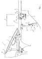
- Fig. 1 is a generally designated 1 Cabriolet vehicle fragmentary illustrated in a schematic representation of his rear area, with a closed illustrated folding top 2 has an integrated in the roof skin 3 rear window 4. From the illustrated closed position, the folding top 2 in the open position (not shown) in a closable with a top compartment lid 8 top compartment 6 can be stored.
- the top compartment lid 8 is in particular by two mirror images of the vehicle longitudinal center plane opposite hinge devices 7 and 7 '(in the side view according to Fig. 1 and 2 is not visible) pivotally supported on the vehicle body. Forward in the direction of travel of the top compartment lid 8 cooperates with at least one provided in the region of an edge Verdeckstoffspannbügels 9 locking device 10 ( Fig. 1 ). Out EP 0 638 453 B1 It is known that in the area of such closing devices 10 of the top compartment lid 8 with the top fabric clamp 9 by a pivot-push movement is locked or unlocked in the opposite direction.
- the lifting drive 11 engages at a distance A in front of the hinge device 7, the top compartment lid 8.
- the lifting drive 11 engages with a substantially vertical Hubachse H at one connected to the top compartment box 8 actuator 12 in the region of a hinge connection 13.
- the top compartment lid 8 connected to the hinge device 7 is articulated in the region of a connecting part 14 having a hinge 14 'on a hinge lifter 15 provided as a supporting part (FIG. Fig. 3 ), on the other hand in the region of a first joint 16 having pivot support on the frame part T of the hinge device 7 is supported.
- the connecting part 14 can be pivoted relative to the hinge lifter 15 so that thereby the top compartment lid 8, in particular in the first phase (FIG. Fig. 3 to Fig. 4 ) at the opening process (or in reverse order in the final phase when closing the top compartment lid) on the front closure device 10 ( Fig. 1 ) can experience effective tilting.
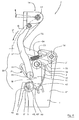
- the hinge device 7 is illustrated in detail in each individual representation, wherein in the inventive design in the vicinity of the hinge lifter 15 has an effective between the connecting part 14 and the frame part T, designated generally by 30 movement lock ( Fig. 5 : Locked position).
- This movement lock 30 is in the opening of the top compartment lid 8 in one of its return movement (arrow D in Fig. 4 ) in the region of the hinge lever 15 counteracting holding position displaced and closing the top compartment lid 8, the movement lock 30 is releasable, so that a controlled in the hinge device 7 return movement of the hinge lifter 15 is reached with the lid 8.
- the movement lock 30 acts together with a frame side only on the hinge lifter 15 in the region of a transverse axis 36 at this articulated control device 31, so that in the displacement of the top compartment lid 8 and des Hinge 15 effective movement phases are accurately transferred to the parts of the movement lock 30 and this particular in a clamping position ( Fig. 5 . Fig. 6 ) is lockable.
- the hinge device 7 is provided to stabilize the system in the region of the hinge lifter 15 with the respective movement of the control module 31 and / or the top compartment lid 8 supporting spring assemblies, which have two leaf springs 32 and 33 and a tension spring 34.
- the composite of the partial movement paths D and G displacement of the top compartment cover 8 and the connecting part 14 is controlled in the hinge device 7 characterized in that the hinge lever 15 is formed as a substantially L-shaped pivot lever 21.
- the L-pivot lever 21 is articulated on the one hand by the connecting part 14 with the top compartment lid. 8 connected, on the other hand, supported on the body-mounted hinge frame T by the hinge connection 16 and between these two joints 14 'and 16 is on the L-pivot lever 21 a lug portion 35 (FIG. Fig. 6 ) is provided, on which in the region of a transverse axis 36 to the connecting part 14 upwardly guided control device 31 is articulated.
- the hinge device 7 is constructed substantially mirror-inverted to its central longitudinal plane M 'and provided with two of the L-pivot lever 21 and 21', which have a common pivot axis 16 'on the frame part T in the region of the first hinge connection 16.
- the control device 31 is advantageously supported between the two L-shaped pivoting levers 21 and 21 'with its transverse axis 36 and from this starting a centrally extending control lever 37 is pivotally supported by a neck portion 38 on the pivotal connecting part 14 by a hinge 39.
- FIG. 5 shows the structure of the control device 31 used for the movement lock 30, wherein this has a pivotable control disk 41 in the region of its transverse axis 36, on the other hand connected to the movement of the top compartment cover 8 from the connecting part 14 control lever 37 and near this connection region with a clamping profile part 42nd is provided.
- the clamping profile part 42 is displaceable towards a frame-side stationary counter member in the form of a contact shaft 43, with the in the contact position ( Fig. 5 )
- a clamping connection is constructed so that the parts 42 and 43 block further movement.
- control lever 37 of the control device 31 is guided in a slot 44 of the control disk 41 by means of a hinge pin 45.
- the control disk 41 is held by means of the attacking above the elongated hole 44 tension spring 34 in a permanent setpoint on the control lever 37 until the movement lock is effective.
- the parts to each other and frame side in the hinge device 7 are characterized braced against each other, that between the control device 31 and the two hinge pins 21, 21 ', the two between the upper transverse axis 38 and the lower abutment shaft 43 extending leaf springs 31, 33 with their double arcuately curved ends 50, 50 'on the contact shaft 43 and the transverse axis 36 are applied.
- the abutment shaft 43 is held by spring force in its clamping profile part 42 in the region of a cylindrical bearing block 46 under cross-use position between the legs T 'and T "of the frame part T.
- This blocking can be based on Fig. 5 by means of the lifting drive 11 in reverse motion sequence (corresponding Fig. 4 and 3 ) are unlocked during the automatic closing operation in that the retracting control lever 37 (arrow Z ', Fig. 5 ) in the slot 44 at the lower portion 47 comes to rest. Thereafter, the clamping force of the control disk 41 on the cylindrical system cam 46 of the abutment shaft 43 by means of the control lever 37 is achieved in that it displaces the control disk 41 in an arrow W '( Fig. 4 ). The closing movement of the top compartment lid 8 is now opposite to in Fig. 3 illustrated opening movements (arrow D, K) continued and the top compartment lid 8 can be locked in the region of the locking device 10.
- the hinge device 7 is provided in the region of the movement lock 30 with an emergency release, which is provided in the illustrated embodiment in the region of the contact shaft 43.
- an emergency release is at the contact shaft 43 ( Fig. 6 ) at least one of these against the clamping force of the leaf springs 31, 33 pivoting hand lever 48 (or on the other hand 48 ') is provided.
- This possibility of unlocking is achieved in that the leaf springs 32 and 33 respectively on both sides of the cylindrical bearing cam 46 for the middle control disk 41 with an off-center to the longitudinal axis S of the contact shaft 43 extending and thus eccentrically shaped cam member 49, 49' ( Fig. 5 ) are supported on the abutment shaft 43.
Landscapes
- Engineering & Computer Science (AREA)
- Mechanical Engineering (AREA)
- Vehicle Step Arrangements And Article Storage (AREA)
- Hinges (AREA)
- Superstructure Of Vehicle (AREA)
Claims (17)
- Véhicule cabriolet avec un compartiment de capote (6) recevant sa capote (2) en position d'ouverture, ledit compartiment de capote (6) comprenant un couvercle (8) qui présente au moins un dispositif charnière (7; 7') monté fixe à la carrosserie pour supporter le couvercle (8) du compartiment de capote en pivotement, caractérisé en ce qu'un élément de cadre (T) du dispositif charnière (7; 7') comprend au moins un bras de charnière (15) qui est pivotable au moyen d'une première articulation (16) et qui est articulé, d'autre part, sur le couvercle (8) du compartiment de capote au moyen d'un élément de liaison (14) comprenant une deuxième articulation (14'), le bras de charnière (15) présentant, entre l'élément de liaison (14) et l'élément de cadre (T), un élément de blocage de mouvement (30) intégré qui peut être guidé par le mouvement d'ouverture du couvercle (8) du compartiment de capote vers une position de maintien opposant le mouvement de retour du couvercle (8) du compartiment de capote et que l'on peut débloquer pour fermer le couvercle (8) du compartiment de capote.
- Véhicule cabriolet selon la revendication 1, caractérisé en ce que l'élément de blocage de mouvement (30) coopère avec un dispositif de commande (31) articulé sur le bras de charnière (15).
- Véhicule cabriolet selon la revendication 1 ou 2, caractérisé en ce que le bras de charnière (15) en appui sur l'élément de cadre (T) est pivotable (flèche D), pendant l'opération d'ouverture initiée par un entraînement de levage (11) sur le couvercle (8) du compartiment de capote, vers une butée (23) montée fixe au cadre, et le couvercle (8) du compartiment de capote est pivotable encore plus (flèche G) lorsque le bras de charnière (15) se trouve en position d'appui, permettant le déplacement de l'élément de blocage de mouvement (30), guidé par le dispositif de commande (31), vers une position de blocage.
- Véhicule cabriolet selon l'une quelconque des revendications 1 à 3, caractérisé en ce que le couvercle (8) du compartiment de capote est pivotable lui-même (flèche K), par rapport au bras de charnière (15), dans la région de l'élément de liaison (14).
- Véhicule cabriolet selon l'une quelconque des revendications 1 à 4, caractérisé en ce que l'élément de blocage de mouvement (30) peut être retourné par l'entraînement de levage (11) vers une position de déblocage.
- Véhicule cabriolet selon l'une quelconque des revendications 1 à 5, caractérisé en ce que le bras de charnière (15) est respectivement relié au dispositif de commande (31) ou à l'élément de cadre (T) par un ensemble de ressorts (32, 33; 34) aidant à effectuer le mouvement respectif du couvercle (8) du compartiment de capote.
- Véhicule cabriolet selon l'une quelconque des revendications 1 à 6, caractérisé en ce que le bras de charnière (15) est réalisé en tant que levier de pivotement (21; 21') sensiblement en forme de L, ledit levier (21; 21') étant articulé d'une part sur le couvercle (8) du compartiment de capote par l'élément de liaison (14) et comprenant d'autre part la première articulation (16) sur le cadre charnière (T) monté fixe sur la carrosserie, et ledit levier (21; 21') présentant un ajutage (35) entre ces deux articulations (14 et 16), sur lequel un levier de commande (37) du dispositif de commande (31) est articulé dans la région d'un axe transversal (36), ledit levier de commande (37) venant en prise dans l'élément de liaison (14).
- Véhicule cabriolet selon l'une quelconque des revendications 1 à 7, caractérisé en ce que le dispositif charnière (31) présente au moins deux leviers de pivotement (21, 21') en forme de L ayant un axe de pivotement commun sur l'élément de cadre (T) dans la région de la première articulation (16).
- Véhicule cabriolet selon l'une quelconque des revendications 1 à 8, caractérisé en ce que le dispositif de commande (31) est supporté entre les deux leviers de pivotement (21, 21') en forme de L selon son axe transversal (36), à partir duquel le levier de commande (37) est supporté à l'autre extrémité par un ajutage (38) sur l'élément de liaison (14) de manière articulée (au numéro 39).
- Véhicule cabriolet selon l'une quelconque des revendications 1 à 9, caractérisé en ce que le dispositif de commande (31) maintient un disque de commande (41), dans la région de son axe transversal (36), ledit disque de commande (41) étant relié, d'autre part, avec le levier de commande (37) qui reçoit le mouvement du couvercle (8) du compartiment de capote transmis par l'élément de liaison (14), et présentant une pièce de profilé de serrage (42) de manière à pouvoir déplacer ladite pièce de profilé de serrage (42) vers un élément d'appui (43) du côté du cadre, et l'élément de blocage de mouvement (30) est réalisé par une liaison par force, par complémentarité de forme et/ou par friction.
- Véhicule cabriolet selon l'une quelconque des revendications 1 à 10, caractérisé en ce que le levier de commande (37) est guidé dans un trou oblong (44) du disque de commande (41).
- Véhicule cabriolet selon l'une quelconque des revendications 1 à 11, caractérisé en ce qu'un arbre d'appui (43) est associé, comme élément complémentaire de l'élément de blocage de mouvement (30), au dispositif de commande (31) dans la région de la pièce de profilé de serrage (42), qui est déplaçable avec le disque de commande (41), ledit arbre d'appui (43) étant supporté en pivotement sur l'élément de cadre (T' et T").
- Véhicule cabriolet selon l'une quelconque des revendications 1 à 12, caractérisé en ce que le disque de commande (41) est supporté dans une position de consigne sur le levier de commande (37) par un ressort de traction (34) qui vient en prise au-dessus du trou oblong (44).
- Véhicule cabriolet selon l'une quelconque des revendications 1 à 13, caractérisé en ce que deux ressorts à lames (32, 33), s'étendant entre l'axe transversal supérieur (36) et l'arbre d'appui inférieur (43), sont prévus en tant qu'ensemble de ressorts entre le dispositif de commande (31) et le bras de charnière (15), lesdits ressorts fixant l'arbre d'appui (43) dans sa position d'utilisation en prise au-dessous de la pièce de profilé de serrage (42) dans la région d'une came d'appui (46) cylindrique.
- Véhicule cabriolet selon l'une quelconque des revendications 1 à 14, caractérisé en ce que la position de freinage, de verrouillage et/ou de point mort générée entre la came d'appui (46) cylindrique de l'arbre d'appui (43) et la pièce de profilé de serrage (42) est libérable par un déverrouillage d'urgence.
- Véhicule cabriolet selon la revendication 15, caractérisé en ce que l'on prévoit un levier manuel (48) comme déverrouillage d'urgence sur l'arbre d'appui (43), ledit levier manuel (48) pivotant l'arbre d'appui (43) à l'opposée (flèche S') de la force élastique exercée par les ressorts à lames (32, 33).
- Véhicule cabriolet selon la revendication 15 ou 16, caractérisé en ce qu'une ressort à lames (32, 33) respective est supportée sur l'arbre d'appui (43) sur les deux côtés de la came d'appui (46) cylindrique centrale pour le disque de commande (41) au moyen d'un élément de came (49, 49') de forme excentrique et s'étendant de manière excentrique par rapport à l'axe longitudinal (S) de l'arbre d'appui (43).
Applications Claiming Priority (3)
| Application Number | Priority Date | Filing Date | Title |
|---|---|---|---|
| DE10247724 | 2002-10-12 | ||
| DE10247724A DE10247724B3 (de) | 2002-10-12 | 2002-10-12 | Cabriolet-Fahrzeug mit das Verdeck aufnehmendem Verdeckkasten |
| PCT/DE2003/003281 WO2004035338A1 (fr) | 2002-10-12 | 2003-10-04 | Vehicule cabriolet comportant un caisson recevant la capote |
Publications (2)
| Publication Number | Publication Date |
|---|---|
| EP1554151A1 EP1554151A1 (fr) | 2005-07-20 |
| EP1554151B1 true EP1554151B1 (fr) | 2013-04-24 |
Family
ID=32102750
Family Applications (1)
| Application Number | Title | Priority Date | Filing Date |
|---|---|---|---|
| EP03775047.8A Expired - Lifetime EP1554151B1 (fr) | 2002-10-12 | 2003-10-04 | Véhicule cabriolet comportant un caisson recevant la capote |
Country Status (4)
| Country | Link |
|---|---|
| US (1) | US7182388B2 (fr) |
| EP (1) | EP1554151B1 (fr) |
| DE (1) | DE10247724B3 (fr) |
| WO (1) | WO2004035338A1 (fr) |
Cited By (1)
| Publication number | Priority date | Publication date | Assignee | Title |
|---|---|---|---|---|
| DE102014221843A1 (de) * | 2014-10-27 | 2016-04-28 | Bayerische Motoren Werke Aktiengesellschaft | Kraftfahrzeug |
Families Citing this family (10)
| Publication number | Priority date | Publication date | Assignee | Title |
|---|---|---|---|---|
| DE102004052236A1 (de) | 2004-10-27 | 2006-05-04 | Wilhelm Karmann Gmbh | Verriegelungseinrichtung für ein Cabrioletverdeck |
| DE102005012222A1 (de) * | 2005-03-15 | 2006-09-28 | Webasto Ag | Fahrzeug mit einem Verdeck und einer Heckklappe |
| DE102005033537B4 (de) * | 2005-07-14 | 2009-11-26 | Magna Car Top Systems Gmbh | Stelleinrichtung für Bauteile |
| DE102005033609B4 (de) * | 2005-07-14 | 2013-02-07 | Webasto Ag | Antriebsvorrichtung eines bewegbaren Bauteils eines Fahrzeugs |
| JP4842681B2 (ja) | 2006-03-28 | 2011-12-21 | ベバスト ジャパン株式会社 | リンク機構 |
| DE102007013517B4 (de) * | 2007-03-21 | 2016-11-10 | Valmet Automotive Oy | Betätigungsvorrichtung für ein bewegliches Verkleidungselement, insbesondere Gestängeklappe, und Cabrioletfahrzeug mit einem solchen Verkleidungselement oder einer solchen Gestängeklappe |
| CN101161493B (zh) * | 2007-11-12 | 2011-06-08 | 奇瑞汽车有限公司 | 汽车可伸缩顶蓬的铰链支撑座 |
| US7819459B2 (en) * | 2009-02-11 | 2010-10-26 | Valmet Automotive Oy | Convertible vehicle |
| DE102017100893B4 (de) | 2017-01-18 | 2021-12-09 | Webasto SE | Cabriolet-Verdeck mit Hauptlenkeranschlaganordnung |
| DE102022116438A1 (de) * | 2022-07-01 | 2024-01-04 | Bayerische Motoren Werke Aktiengesellschaft | Frontklappenscharnier für ein Kraftfahrzeug und Kraftfahrzeug mit einem derartigen Frontklappenscharnier |
Family Cites Families (8)
| Publication number | Priority date | Publication date | Assignee | Title |
|---|---|---|---|---|
| US2966697A (en) * | 1958-05-16 | 1961-01-03 | Mintz Julius | Self-locking hinge |
| DE3937764C2 (de) | 1989-11-14 | 1995-02-23 | Bayerische Motoren Werke Ag | Antriebsvorrichtung, insbesondere für ein Kraftfahrzeug-Faltverdeck |
| DE9311798U1 (de) * | 1993-08-07 | 1994-12-08 | Wilhelm Karmann GmbH, 49084 Osnabrück | Versenkbares Faltverdeck für ein Cabriolet-Fahrzeug |
| DE29801914U1 (de) | 1998-02-05 | 1999-02-18 | Wilhelm Karmann GmbH, 49084 Osnabrück | Antriebsvorrichtung für den Verdeckkastendeckel eines Cabriolet-Fahrzeugs |
| DE19912893C2 (de) | 1999-03-23 | 2003-02-27 | Daimler Chrysler Ag | Cabrio-Fahrzeug mit einem Verdeck |
| DE19959700C1 (de) | 1999-12-10 | 2001-02-22 | Daimler Chrysler Ag | Antriebsanordnung zum Bewegen eines verriegelbaren Kraftfahrzeugteils |
| DE19960905C1 (de) * | 1999-12-17 | 2001-05-10 | Cts Fahrzeug Dachsysteme Gmbh | Verstellbarer Deckel in der Verkleidung eines Fahrzeugs |
| DE20004535U1 (de) * | 2000-03-10 | 2001-02-08 | Wilhelm Karmann GmbH, 49084 Osnabrück | Cabriolet-Fahrzeug mit einem unterhalb eines Verdeckkastendeckels ablegbaren Verdeck |
-
2002
- 2002-10-12 DE DE10247724A patent/DE10247724B3/de not_active Withdrawn - After Issue
-
2003
- 2003-10-04 WO PCT/DE2003/003281 patent/WO2004035338A1/fr not_active Ceased
- 2003-10-04 US US10/531,100 patent/US7182388B2/en not_active Expired - Fee Related
- 2003-10-04 EP EP03775047.8A patent/EP1554151B1/fr not_active Expired - Lifetime
Cited By (2)
| Publication number | Priority date | Publication date | Assignee | Title |
|---|---|---|---|---|
| DE102014221843A1 (de) * | 2014-10-27 | 2016-04-28 | Bayerische Motoren Werke Aktiengesellschaft | Kraftfahrzeug |
| DE102014221843B4 (de) | 2014-10-27 | 2021-12-09 | Bayerische Motoren Werke Aktiengesellschaft | Kraftfahrzeug |
Also Published As
| Publication number | Publication date |
|---|---|
| US20060038426A1 (en) | 2006-02-23 |
| DE10247724B3 (de) | 2004-05-13 |
| WO2004035338A1 (fr) | 2004-04-29 |
| US7182388B2 (en) | 2007-02-27 |
| EP1554151A1 (fr) | 2005-07-20 |
Similar Documents
| Publication | Publication Date | Title |
|---|---|---|
| DE102004022426B4 (de) | Heckklappenanordnung | |
| EP0763439B1 (fr) | Capote pour véhicule, en particulier pour cabriolet | |
| DE10313496B4 (de) | Verdeck eines Kraftfahrzeugs | |
| DE4336278A1 (de) | Betätigungseinrichtung für ein Verdeck und einen Verdeckkastendeckel eines Kraftfahrzeuges | |
| EP1112879A2 (fr) | Toit de véhicule convertible | |
| DE19801853C1 (de) | Antriebseinrichtung für einen Verdeckkastendeckel | |
| EP0930187A2 (fr) | Système de verrouillage pour la fixation d'une capote | |
| EP1403116B1 (fr) | Véhicule convertible avec toit pliant rétractable | |
| EP1314601B1 (fr) | Toit ouvrant de véhicule avec une capote pliante | |
| DE10247724B3 (de) | Cabriolet-Fahrzeug mit das Verdeck aufnehmendem Verdeckkasten | |
| DE10216417A1 (de) | Zwischen einer Schließposition und einer Ablageposition verstellbares Fahrzeugdach | |
| DE10247725B4 (de) | Cabriolet-Fahrzeug mit versenkbarem Verdeck | |
| EP1034979B1 (fr) | Plage arrière pour vehicules avec capote pliante | |
| EP1907230B1 (fr) | Dispositif de support pour un couvercle de logement de capote d'une voiture decapotable | |
| DE102004005882B4 (de) | Verdeck eines Kraftfahrzeugs | |
| DE3917284C2 (de) | Verstelleinrichtung an einem Faltverdeck eines Kraftfahrzeugs | |
| DE102005033609B4 (de) | Antriebsvorrichtung eines bewegbaren Bauteils eines Fahrzeugs | |
| DE10117769B4 (de) | Vorrichtung zur Unterstützung einer Öffnungsbewegung einer Fahrzeugklappe | |
| EP1940640B1 (fr) | Dispositif de verrouillage d'un couvercle de logement de capote d'un cabriolet | |
| DE102004017240B4 (de) | Fahrzeugdach eines Cabriolets mit bewegbarer Heckscheibe | |
| EP1810860B1 (fr) | Cinématique à plusieurs articulations pour couvercle de coffre de véhicules à carrosserie ouverte | |
| EP1659016B1 (fr) | Ensemble d'entraînement pour une partie de véhicule | |
| EP2383135B1 (fr) | Couvercle mobile | |
| AT404011B (de) | Seitenwand für den aufbau eines fahrzeuges | |
| EP1798090B1 (fr) | Plage arrière pour cabriolet |
Legal Events
| Date | Code | Title | Description |
|---|---|---|---|
| PUAI | Public reference made under article 153(3) epc to a published international application that has entered the european phase |
Free format text: ORIGINAL CODE: 0009012 |
|
| 17P | Request for examination filed |
Effective date: 20050512 |
|
| AK | Designated contracting states |
Kind code of ref document: A1 Designated state(s): AT BE BG CH CY CZ DE DK EE ES FI FR GB GR HU IE IT LI LU MC NL PT RO SE SI SK TR |
|
| RBV | Designated contracting states (corrected) |
Designated state(s): DE FR GB IT |
|
| 19U | Interruption of proceedings before grant |
Effective date: 20090629 |
|
| 19W | Proceedings resumed before grant after interruption of proceedings |
Effective date: 20101201 |
|
| GRAP | Despatch of communication of intention to grant a patent |
Free format text: ORIGINAL CODE: EPIDOSNIGR1 |
|
| GRAS | Grant fee paid |
Free format text: ORIGINAL CODE: EPIDOSNIGR3 |
|
| GRAA | (expected) grant |
Free format text: ORIGINAL CODE: 0009210 |
|
| AK | Designated contracting states |
Kind code of ref document: B1 Designated state(s): DE FR GB IT |
|
| REG | Reference to a national code |
Ref country code: GB Ref legal event code: FG4D Free format text: NOT ENGLISH |
|
| REG | Reference to a national code |
Ref country code: DE Ref legal event code: R096 Ref document number: 50314779 Country of ref document: DE Effective date: 20130620 |
|
| REG | Reference to a national code |
Ref country code: DE Ref legal event code: R082 Ref document number: 50314779 Country of ref document: DE Representative=s name: KRONTHALER, SCHMIDT & COLL. PATENTANWALTSKANZL, DE |
|
| REG | Reference to a national code |
Ref country code: DE Ref legal event code: R081 Ref document number: 50314779 Country of ref document: DE Owner name: VALMET AUTOMOTIVE OY, FI Free format text: FORMER OWNER: WILHELM KARMANN GMBH, 49084 OSNABRUECK, DE Effective date: 20131022 Ref country code: DE Ref legal event code: R082 Ref document number: 50314779 Country of ref document: DE Representative=s name: KRONTHALER, SCHMIDT & COLL. PATENTANWALTSKANZL, DE Effective date: 20131022 |
|
| PG25 | Lapsed in a contracting state [announced via postgrant information from national office to epo] |
Ref country code: IT Free format text: LAPSE BECAUSE OF FAILURE TO SUBMIT A TRANSLATION OF THE DESCRIPTION OR TO PAY THE FEE WITHIN THE PRESCRIBED TIME-LIMIT Effective date: 20130424 |
|
| PLBE | No opposition filed within time limit |
Free format text: ORIGINAL CODE: 0009261 |
|
| STAA | Information on the status of an ep patent application or granted ep patent |
Free format text: STATUS: NO OPPOSITION FILED WITHIN TIME LIMIT |
|
| 26N | No opposition filed |
Effective date: 20140127 |
|
| REG | Reference to a national code |
Ref country code: DE Ref legal event code: R097 Ref document number: 50314779 Country of ref document: DE Effective date: 20140127 |
|
| REG | Reference to a national code |
Ref country code: GB Ref legal event code: 732E Free format text: REGISTERED BETWEEN 20140925 AND 20141001 |
|
| REG | Reference to a national code |
Ref country code: FR Ref legal event code: TP Owner name: VALMET AUTOMOTIVE OY, FI Effective date: 20150105 |
|
| REG | Reference to a national code |
Ref country code: FR Ref legal event code: PLFP Year of fee payment: 13 |
|
| REG | Reference to a national code |
Ref country code: FR Ref legal event code: PLFP Year of fee payment: 14 |
|
| PGFP | Annual fee paid to national office [announced via postgrant information from national office to epo] |
Ref country code: GB Payment date: 20161025 Year of fee payment: 14 Ref country code: FR Payment date: 20161025 Year of fee payment: 14 |
|
| GBPC | Gb: european patent ceased through non-payment of renewal fee |
Effective date: 20171004 |
|
| REG | Reference to a national code |
Ref country code: FR Ref legal event code: ST Effective date: 20180629 |
|
| PG25 | Lapsed in a contracting state [announced via postgrant information from national office to epo] |
Ref country code: GB Free format text: LAPSE BECAUSE OF NON-PAYMENT OF DUE FEES Effective date: 20171004 |
|
| PG25 | Lapsed in a contracting state [announced via postgrant information from national office to epo] |
Ref country code: FR Free format text: LAPSE BECAUSE OF NON-PAYMENT OF DUE FEES Effective date: 20171031 |
|
| PGFP | Annual fee paid to national office [announced via postgrant information from national office to epo] |
Ref country code: DE Payment date: 20211122 Year of fee payment: 19 |
|
| REG | Reference to a national code |
Ref country code: DE Ref legal event code: R119 Ref document number: 50314779 Country of ref document: DE |
|
| PG25 | Lapsed in a contracting state [announced via postgrant information from national office to epo] |
Ref country code: DE Free format text: LAPSE BECAUSE OF NON-PAYMENT OF DUE FEES Effective date: 20230503 |