EP1554437B1 - Säule-mischbatterie mit handsprühvorrichtung für waschbecken - Google Patents
Säule-mischbatterie mit handsprühvorrichtung für waschbecken Download PDFInfo
- Publication number
- EP1554437B1 EP1554437B1 EP03758317A EP03758317A EP1554437B1 EP 1554437 B1 EP1554437 B1 EP 1554437B1 EP 03758317 A EP03758317 A EP 03758317A EP 03758317 A EP03758317 A EP 03758317A EP 1554437 B1 EP1554437 B1 EP 1554437B1
- Authority
- EP
- European Patent Office
- Prior art keywords
- pillar
- tap
- mixing chamber
- hand spray
- outlet
- Prior art date
- Legal status (The legal status is an assumption and is not a legal conclusion. Google has not performed a legal analysis and makes no representation as to the accuracy of the status listed.)
- Expired - Lifetime
Links
Images

Classifications
-
- E—FIXED CONSTRUCTIONS
- E03—WATER SUPPLY; SEWERAGE
- E03C—DOMESTIC PLUMBING INSTALLATIONS FOR FRESH WATER OR WASTE WATER; SINKS
- E03C1/00—Domestic plumbing installations for fresh water or waste water; Sinks
- E03C1/02—Plumbing installations for fresh water
- E03C1/04—Water-basin installations specially adapted to wash-basins or baths
-
- Y—GENERAL TAGGING OF NEW TECHNOLOGICAL DEVELOPMENTS; GENERAL TAGGING OF CROSS-SECTIONAL TECHNOLOGIES SPANNING OVER SEVERAL SECTIONS OF THE IPC; TECHNICAL SUBJECTS COVERED BY FORMER USPC CROSS-REFERENCE ART COLLECTIONS [XRACs] AND DIGESTS
- Y10—TECHNICAL SUBJECTS COVERED BY FORMER USPC
- Y10T—TECHNICAL SUBJECTS COVERED BY FORMER US CLASSIFICATION
- Y10T137/00—Fluid handling
- Y10T137/2496—Self-proportioning or correlating systems
- Y10T137/2559—Self-controlled branched flow systems
- Y10T137/265—Plural outflows
- Y10T137/2668—Alternately or successively substituted outflow
- Y10T137/268—Responsive to pressure or flow interruption
-
- Y—GENERAL TAGGING OF NEW TECHNOLOGICAL DEVELOPMENTS; GENERAL TAGGING OF CROSS-SECTIONAL TECHNOLOGIES SPANNING OVER SEVERAL SECTIONS OF THE IPC; TECHNICAL SUBJECTS COVERED BY FORMER USPC CROSS-REFERENCE ART COLLECTIONS [XRACs] AND DIGESTS
- Y10—TECHNICAL SUBJECTS COVERED BY FORMER USPC
- Y10T—TECHNICAL SUBJECTS COVERED BY FORMER US CLASSIFICATION
- Y10T137/00—Fluid handling
- Y10T137/6416—With heating or cooling of the system
- Y10T137/6579—Circulating fluid in heat exchange relationship
-
- Y—GENERAL TAGGING OF NEW TECHNOLOGICAL DEVELOPMENTS; GENERAL TAGGING OF CROSS-SECTIONAL TECHNOLOGIES SPANNING OVER SEVERAL SECTIONS OF THE IPC; TECHNICAL SUBJECTS COVERED BY FORMER USPC CROSS-REFERENCE ART COLLECTIONS [XRACs] AND DIGESTS
- Y10—TECHNICAL SUBJECTS COVERED BY FORMER USPC
- Y10T—TECHNICAL SUBJECTS COVERED BY FORMER US CLASSIFICATION
- Y10T137/00—Fluid handling
- Y10T137/8593—Systems
- Y10T137/87249—Multiple inlet with multiple outlet
-
- Y—GENERAL TAGGING OF NEW TECHNOLOGICAL DEVELOPMENTS; GENERAL TAGGING OF CROSS-SECTIONAL TECHNOLOGIES SPANNING OVER SEVERAL SECTIONS OF THE IPC; TECHNICAL SUBJECTS COVERED BY FORMER USPC CROSS-REFERENCE ART COLLECTIONS [XRACs] AND DIGESTS
- Y10—TECHNICAL SUBJECTS COVERED BY FORMER USPC
- Y10T—TECHNICAL SUBJECTS COVERED BY FORMER US CLASSIFICATION
- Y10T137/00—Fluid handling
- Y10T137/8593—Systems
- Y10T137/87571—Multiple inlet with single outlet
- Y10T137/87676—With flow control
- Y10T137/87684—Valve in each inlet
Definitions
- This invention relates to pillar taps in which the tap body is mounted some distance above a work top, and in particular to taps having a mixing system to mix hot and cold water and a separate manually operated spray nozzle attached to the water mixer by a flexible tube. Such arrangements are often found in domestic kitchens.
- GB2361047 discloses a pillar tap mixer according to the preamble of claim 1, that provides a spray nozzle with a separate flexible hose.
- the water supply to the spray nozzle, and control of the temperature of the water so supplied, comes from the same mixer system as that used for the tap nozzle via a diverter in the mixing chamber. Whilst this system does provide a spray nozzle, it has a number of disadvantages.
- One disadvantage is that the mixing chamber is under the mounting surface, occupying a large amount of space.
- the valves controlling the water flow are housed below the mounting surface and controlled by long spindles extending down from the tap levers, through the pillars.
- Tap housings at the top of the pillar steams house the valve chambers and connect via a bridge.
- a mixing chamber is positioned on the bridge and an outlet nozzle extends from the mixing chamber.
- the water passage from one tap housing to the mixing chamber runs alongside a return passage from the mixing chamber to the housing, Within the pillar supporting the tap housing is a passage supplying water to the valve and another passage delivering the water from the return passage to the hose of a hand spray.
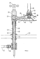
- FIG. 1 shows a pillar mixer tap forming an embodiment of the present invention.
- the mixer is mounted on a mounting surface 2, such as a kitchen top or sink rim, in which two holes 4, 6 are formed to receive the two tap pillars 8, 10. Hot water enters the pillar sink mixer through the tap pillar 8, and cold water enters the pillar sink mixer through pillar 10.
- Each pillar 8, 10 has a housing 12, 14 at its top end which houses a valve chamber and valve 16 operated by levers or handles 18, 20.
- the housings 12, 14 are both in fluid connection with a mixing chamber 22 via passages 24 and 26 respectively in a bridge 28.
- the mixing chamber 22 houses a diverter valve 32 which determines the direction of flow of the mixed water from the mixing chamber 22.
- the diverter valve 32 has two outlets 34, 36 which lead respectively to tap nozzle 30 and a hand spray 38.
- the diverter valve 32 is an exclusive output system, therefore whilst the hand spray 38 is in operation, substantially no water will pass to the tap nozzle 30.
- the operation of diverter valves is well known and is described for example in USA-4,609,006 .
- the hand spray outlet channel which provides a fluid communication channel for the mixed water from the mixing chamber 22 to the hand spray 38, comprises three portions 40, 42, 44.
- the first portion comprises a passage 40 from the second outlet 36 of the mixing chamber 22 to the tap housing 14.
- Passage 40 is housed within bridge 28, alongside passage 26.
- the second portion comprises passage 42 that is defined by the wall of tap pillar 10.
- Within the pillar 10 is a tube 46 which delivers cold water up through the pillar 10 to valve 16.
- Tube 46 is sealed at its upper end to a valve seat 50 in partition wall 52.
- Tube 46 extends down within pillar10.
- the third portion of the hand spray outlet channel is a flexible hose 44 that provides fluid communication from an outlet 48 from the lower end of the tap pillar 10, beneath the mounting surface 2 to the hand spray 38.
- a T-shaped union is mounted on the lower end of pillar 10 and tube 46 passes through union 54, with a seal 56 being provided between the tube 46 and union 54 at the lower outlet of the union 54.
- Flexible hose 44 is coupled to the side outlet of the union 54, in fluid communication with passage 42. The hand spray 38 can be lifted out from the mounting surface 2.
- Valves 16 are opened by turning handles 18, 20 to give the required water flow through nozzle 30 via mixing chamber 22. Cold water passing through passage 46, via valve 16 to passage 26, chamber 22 and nozzle 30. When a push button valve on hand spray 38 is pressed, water can flow from spray 38. Diverter valve 22 is caused to move to close off the outlet 34 to nozzle 30, by the pressure differential across the valve ends, so that water will then flow out of mixing chamber outlet 36. Water flows through passages 40, 42 and hose 44 to spray 38.
- passage 40 may be directed towards hot tap housing 12, pillar 8 enclosing the passage 46 and connecting with the hose 44.
- the invention provides a pillar mixer with a hand spray function and yet with minimal additional space requirement.
Landscapes
- Health & Medical Sciences (AREA)
- Life Sciences & Earth Sciences (AREA)
- Engineering & Computer Science (AREA)
- Hydrology & Water Resources (AREA)
- Public Health (AREA)
- Water Supply & Treatment (AREA)
- Domestic Plumbing Installations (AREA)
- Nozzles (AREA)
Claims (4)
- Säulenmischbatterie mit einer Handsprühvorrichtung (38), in der ein Heißwasser - und Kaltwasserventil auf den jeweiligen Säulen (8, 10) getragen werden, wobei die Säulen (8, 10) mittels einer Brücke (28) verbunden sind, die eine Zaptbabrtdüse (30) trägt,
dadurch gekennzeichnet, dass die Brücke (28) eine Mischkammer (22) aufweist, und wobei sich ein Wasserdurchgang von der Mischkammer (22) zur Handsprühvorrichtung (38) durch eine der Säulen (8, 10) ersteckt. - Säulenmischbatterie für Waschbecken nach Anspruch 1, bei der:die Heißwasserzapfhahnsäule (8) und die Kaltwasserzapfltahnsäule (10) in einer beabstandeten Beziehung sind, wobei jede Zapfhahnsäule (8, 10) ein Wasserventilgehäuse (12, 14) umfasst, das sich über einer Montagefläche (2) befindet;sich die Mischkammer (22) in der Brücke (28) über der Montagefläche (2) zwischen den Wasserventilgehäusen (12, 14) befindet, wobei die Mischkammer (22) ausweist: einen ersten Einlass in Flüssigkeitsverbindung mit dem Wasserventilgehäuse (12) der Heißwasserzapfhahsäule (8) mittels einer ersten Leitung (24); einen zweiten Einlass in Flüssigkeitsverbindung mit dem Wasserventilgehäuse (14) der Kaltwasserzapfhahnsäule (10) mittels einer zweiten Leitung (26); und zwei Auslässe (34, 36), wobei ein erster Auslass (34) in Flüssigkeitsverbindung mit der Zapfhahndüse (30) und ein zweiter Auslass (36) in Flüssigkeitsverbindung mit der Handsprühvorrichtung (38) ist; undwobei die Handsprühvorrichutng (38) in Flüssigkeitsverbindung mit dem zweiten Auslass (36) der Mischkammer (22) durch einen Auslassdurchgang (40, 42, 44) der Handsprühvorrichtung ist, wobei ein Teil davon in mindestens einem von Brücke (28) und einer Zapfhahnsäule (8; 10) untergebracht ist.
- Säulenmischbatterie für Waschbecken nach Anspruch 2, bei der die Mischkammer (22) ein Umleitventil (32) umfasst, das angeordnet ist, um den Fluss des Mischwassers vom ersten Auslass (34) der Mischkammer (22) zum zweiten Auslass (36) der Mischkammer (22) umzuleiten, wobei der zweite Auslass (36) in Flüssigkeitsverbindung mit der Handsprühvorrichtung (38) ist, wenn die Handsprühvorrichtung (38) betätigt wird, um Wasser daraus zu entnahmen.
- Säulenmischbatterie für Waschbecken nach Anspruch 1, bei der sich die Heißwasserzapfhahnsäule (8) und die Kaltwasserzapfhahnsäule (10), die mittels der Brücke (28) verbunden sind, bei Benutzung über einer Montagefläche (2) befinden;
ein Umleitventil (32) in der Brücke (28) vorhanden ist und Auslässe in Flüssigkeitsverbindung mit der Zapfhahndüse (30), die auf der Brücke (28) montiert ist, und mit der Handsprühvorrichtung (38) aufweist;
sich ein Teil eines Durchganges (40, 42, 44), der die Flüssigkeitsverbindung zwischen dem Umleitventil (32) und der Handsprühvorrichtung (38) bewirkt, innerhalb einer der Zapfhahnsäulen (8, 10) befindet.
Applications Claiming Priority (3)
| Application Number | Priority Date | Filing Date | Title |
|---|---|---|---|
| GB0224580A GB2394525B (en) | 2002-10-22 | 2002-10-22 | A pillar sink mixer with hand spray |
| GB0224580 | 2002-10-22 | ||
| PCT/GB2003/004478 WO2004038111A1 (en) | 2002-10-22 | 2003-10-22 | A pillar sink mixer with hand spray |
Publications (2)
| Publication Number | Publication Date |
|---|---|
| EP1554437A1 EP1554437A1 (de) | 2005-07-20 |
| EP1554437B1 true EP1554437B1 (de) | 2013-01-16 |
Family
ID=9946363
Family Applications (1)
| Application Number | Title | Priority Date | Filing Date |
|---|---|---|---|
| EP03758317A Expired - Lifetime EP1554437B1 (de) | 2002-10-22 | 2003-10-22 | Säule-mischbatterie mit handsprühvorrichtung für waschbecken |
Country Status (6)
| Country | Link |
|---|---|
| US (1) | US7096879B2 (de) |
| EP (1) | EP1554437B1 (de) |
| AU (1) | AU2003274329A1 (de) |
| GB (1) | GB2394525B (de) |
| NZ (1) | NZ540222A (de) |
| WO (1) | WO2004038111A1 (de) |
Families Citing this family (20)
| Publication number | Priority date | Publication date | Assignee | Title |
|---|---|---|---|---|
| US7269864B2 (en) * | 2002-04-17 | 2007-09-18 | Masco Corporation Of Indiana | Mounting system for a faucet |
| AU2003245241A1 (en) * | 2002-04-17 | 2003-11-03 | Masco Corporation Of Indiana | Top down mounting system for faucet |
| US7216663B2 (en) * | 2004-10-05 | 2007-05-15 | Brasstech Inc. | Diverting device for bridge faucet with hand spray |
| EP1877628A2 (de) * | 2005-03-14 | 2008-01-16 | Masco Corporation Of Indiana | Schnellwechselmontagesystem für einen wasserhahn |
| GB0516265D0 (en) * | 2005-08-08 | 2005-09-14 | Hornbeam Ivy Ltd | Spray device |
| GB0516264D0 (en) * | 2005-08-08 | 2005-09-14 | Hornbeam Ivy Ltd | Mixer tap |
| US7698755B2 (en) * | 2005-08-29 | 2010-04-20 | Masco Corporation Of Indiana | Overhead cam faucet mounting system |
| GB2434853B (en) * | 2006-02-02 | 2010-06-16 | Hornbeam Ivy Ltd | Spray device |
| GB2436606B (en) * | 2006-03-29 | 2010-09-15 | Aqualisa Products Ltd | Water valve assembly |
| GB0614470D0 (en) * | 2006-07-20 | 2006-08-30 | Hornbeam Ivy Ltd | Bridge mixer tap |
| US7721761B2 (en) * | 2007-01-31 | 2010-05-25 | Masco Corporation Of Indiana | Diverter integrated into a side sprayer |
| GB0707326D0 (en) | 2007-04-16 | 2007-05-23 | Avilion Ltd | Diverter valve |
| US7934520B2 (en) | 2007-05-08 | 2011-05-03 | Kohler Co. | Coupling assembly for plumbing fitting |
| US8407828B2 (en) | 2007-11-30 | 2013-04-02 | Masco Corporation Of Indiana | Faucet mounting system including a lift rod |
| US20090288715A1 (en) * | 2008-05-20 | 2009-11-26 | Granger Sr Gregory Michael | Hot water recirculator using piping venturi |
| WO2009143352A1 (en) | 2008-05-21 | 2009-11-26 | Masco Corporation Of Indiana | Integrated kitchen faucet side spray and diverter |
| US8297303B2 (en) * | 2009-09-30 | 2012-10-30 | Emerson Electric Co. | Self cleaning valve assembly |
| CA2796796C (en) | 2010-05-21 | 2015-03-24 | Masco Corporation Of Indiana | Faucet mounting anchor |
| KR101939002B1 (ko) | 2014-09-10 | 2019-01-15 | 에이에스 아이피 홀드코 엘엘씨 | 다중 채널 배관 제품 |
| CN113898036A (zh) * | 2021-09-24 | 2022-01-07 | 瑞安市金都洁具有限公司 | 一种多功能的洗脸盆水龙头 |
Family Cites Families (13)
| Publication number | Priority date | Publication date | Assignee | Title |
|---|---|---|---|---|
| US1790625A (en) * | 1931-01-27 | Eatjcet | ||
| US1704198A (en) * | 1927-02-17 | 1929-03-05 | Milwaukee Flush Valve Company | Plumbing fixture |
| US2025825A (en) * | 1930-12-13 | 1935-12-31 | Ricefield Louis | Coupling |
| US2741258A (en) * | 1952-05-02 | 1956-04-10 | Modern Faucet Mfg Co | Anti-siphon manual diverter |
| US2830618A (en) * | 1954-12-10 | 1958-04-15 | William J Mitchell | Hand- and foot-operated sink and lavatory faucet fixture |
| DE3131172A1 (de) * | 1981-08-06 | 1983-02-24 | Kludi-Armaturen Paul Scheffer, 5758 Fröndenberg | "einloch-mischbatterie" |
| US4609006A (en) | 1984-11-29 | 1986-09-02 | American Standard Inc. | Diverter |
| US4706709A (en) * | 1985-03-16 | 1987-11-17 | American Standard Inc. | Mixing valve assembly |
| US5025825A (en) * | 1990-06-15 | 1991-06-25 | Moen Incorporated | Riser spout diverter assembly |
| US5257824A (en) * | 1991-12-30 | 1993-11-02 | Eggen Harald I | Extender for a plumbing mount with spring loaded sealing piston |
| US5778921A (en) * | 1996-05-22 | 1998-07-14 | Chung Cheng Faucet Co., Ltd. | Relay controlling valve structure for twin-tap faucet |
| US5881754A (en) * | 1997-08-18 | 1999-03-16 | Wei; Ming Te | Valve device for faucet and spray gun |
| GB2361047B (en) * | 2000-04-06 | 2003-12-10 | Barber Wilsons & Company Ltd | Improvements in or relating to taps |
-
2002
- 2002-10-22 GB GB0224580A patent/GB2394525B/en not_active Expired - Fee Related
-
2003
- 2003-10-22 AU AU2003274329A patent/AU2003274329A1/en not_active Abandoned
- 2003-10-22 EP EP03758317A patent/EP1554437B1/de not_active Expired - Lifetime
- 2003-10-22 NZ NZ540222A patent/NZ540222A/en not_active IP Right Cessation
- 2003-10-22 WO PCT/GB2003/004478 patent/WO2004038111A1/en not_active Ceased
- 2003-10-22 US US10/689,679 patent/US7096879B2/en not_active Expired - Lifetime
Also Published As
| Publication number | Publication date |
|---|---|
| AU2003274329A1 (en) | 2004-05-13 |
| WO2004038111A1 (en) | 2004-05-06 |
| GB2394525A (en) | 2004-04-28 |
| GB0224580D0 (en) | 2002-12-04 |
| EP1554437A1 (de) | 2005-07-20 |
| NZ540222A (en) | 2006-10-27 |
| US7096879B2 (en) | 2006-08-29 |
| US20040123910A1 (en) | 2004-07-01 |
| GB2394525B (en) | 2006-01-11 |
Similar Documents
| Publication | Publication Date | Title |
|---|---|---|
| EP1554437B1 (de) | Säule-mischbatterie mit handsprühvorrichtung für waschbecken | |
| EP1253361B1 (de) | Umschaltventil | |
| EP2472150B1 (de) | System und Ventileinheit | |
| US6341617B1 (en) | Taps | |
| US20040011399A1 (en) | Side control faucet with diverter assembly | |
| JPH03504823A (ja) | 流し台混合水栓またはこれに類似したもののためのシヤワーヘツド | |
| GB2426039A (en) | Mixer tap | |
| US7082626B2 (en) | Diverter assembly for roman tub | |
| EP1649110A1 (de) | Filtrationsanordnung für mischventil | |
| US4580600A (en) | Laundry faucet | |
| CN208503562U (zh) | 淋浴龙头水路控制结构 | |
| WO2004104306A1 (en) | A water tap | |
| EP2459909B1 (de) | Fluidzufuhrsystem | |
| CA2515977C (en) | Diverting device for bridge faucet with hand spray | |
| KR20180003628U (ko) | 선반형 샤워수전의 일체형 개폐 및 수로구조 | |
| JP2006169762A (ja) | 分岐接続具 | |
| KR0116837Y1 (ko) | 분리형 카트리지 커버를 갖는 냉, 온수 혼합 수전 | |
| JP2544758Y2 (ja) | 湯水混合栓 | |
| CN222950481U (zh) | 一种浴室龙头结构 | |
| CN217634039U (zh) | 一种新型按键开关调温淋浴龙头 | |
| GB2434853A (en) | Spray device | |
| US11946234B2 (en) | Control valve for at least one sanitary fitting having a diaphragm valve and a multi-port valve | |
| JPH115044A (ja) | 複合シャワー水栓 | |
| JPH0972440A (ja) | 分岐口付き湯水混合栓 | |
| WO2004104459A1 (en) | Faucet with peripheral handle |
Legal Events
| Date | Code | Title | Description |
|---|---|---|---|
| PUAI | Public reference made under article 153(3) epc to a published international application that has entered the european phase |
Free format text: ORIGINAL CODE: 0009012 |
|
| 17P | Request for examination filed |
Effective date: 20050311 |
|
| AK | Designated contracting states |
Kind code of ref document: A1 Designated state(s): AT BE BG CH CY CZ DE DK EE ES FI FR GB GR HU IE IT LI LU MC NL PT RO SE SI SK TR |
|
| AX | Request for extension of the european patent |
Extension state: AL LT LV MK |
|
| DAX | Request for extension of the european patent (deleted) | ||
| RAP1 | Party data changed (applicant data changed or rights of an application transferred) |
Owner name: TRIFLOW CONCEPTS LIMITED |
|
| 17Q | First examination report despatched |
Effective date: 20100804 |
|
| GRAP | Despatch of communication of intention to grant a patent |
Free format text: ORIGINAL CODE: EPIDOSNIGR1 |
|
| GRAP | Despatch of communication of intention to grant a patent |
Free format text: ORIGINAL CODE: EPIDOSNIGR1 |
|
| GRAS | Grant fee paid |
Free format text: ORIGINAL CODE: EPIDOSNIGR3 |
|
| GRAA | (expected) grant |
Free format text: ORIGINAL CODE: 0009210 |
|
| AK | Designated contracting states |
Kind code of ref document: B1 Designated state(s): AT BE BG CH CY CZ DE DK EE ES FI FR GB GR HU IE IT LI LU MC NL PT RO SE SI SK TR |
|
| REG | Reference to a national code |
Ref country code: GB Ref legal event code: FG4D |
|
| REG | Reference to a national code |
Ref country code: CH Ref legal event code: EP |
|
| REG | Reference to a national code |
Ref country code: IE Ref legal event code: FG4D |
|
| REG | Reference to a national code |
Ref country code: CH Ref legal event code: EP Ref country code: AT Ref legal event code: REF Ref document number: 594004 Country of ref document: AT Kind code of ref document: T Effective date: 20130215 |
|
| REG | Reference to a national code |
Ref country code: DE Ref legal event code: R096 Ref document number: 60343134 Country of ref document: DE Effective date: 20130314 |
|
| REG | Reference to a national code |
Ref country code: GB Ref legal event code: 732E Free format text: REGISTERED BETWEEN 20130425 AND 20130501 |
|
| REG | Reference to a national code |
Ref country code: AT Ref legal event code: MK05 Ref document number: 594004 Country of ref document: AT Kind code of ref document: T Effective date: 20130116 |
|
| REG | Reference to a national code |
Ref country code: NL Ref legal event code: VDEP Effective date: 20130116 |
|
| PG25 | Lapsed in a contracting state [announced via postgrant information from national office to epo] |
Ref country code: CY Free format text: LAPSE BECAUSE OF FAILURE TO SUBMIT A TRANSLATION OF THE DESCRIPTION OR TO PAY THE FEE WITHIN THE PRESCRIBED TIME-LIMIT Effective date: 20130116 Ref country code: BG Free format text: LAPSE BECAUSE OF FAILURE TO SUBMIT A TRANSLATION OF THE DESCRIPTION OR TO PAY THE FEE WITHIN THE PRESCRIBED TIME-LIMIT Effective date: 20130416 Ref country code: AT Free format text: LAPSE BECAUSE OF FAILURE TO SUBMIT A TRANSLATION OF THE DESCRIPTION OR TO PAY THE FEE WITHIN THE PRESCRIBED TIME-LIMIT Effective date: 20130116 Ref country code: ES Free format text: LAPSE BECAUSE OF FAILURE TO SUBMIT A TRANSLATION OF THE DESCRIPTION OR TO PAY THE FEE WITHIN THE PRESCRIBED TIME-LIMIT Effective date: 20130427 Ref country code: SE Free format text: LAPSE BECAUSE OF FAILURE TO SUBMIT A TRANSLATION OF THE DESCRIPTION OR TO PAY THE FEE WITHIN THE PRESCRIBED TIME-LIMIT Effective date: 20130116 Ref country code: BE Free format text: LAPSE BECAUSE OF FAILURE TO SUBMIT A TRANSLATION OF THE DESCRIPTION OR TO PAY THE FEE WITHIN THE PRESCRIBED TIME-LIMIT Effective date: 20130116 |
|
| PG25 | Lapsed in a contracting state [announced via postgrant information from national office to epo] |
Ref country code: SI Free format text: LAPSE BECAUSE OF FAILURE TO SUBMIT A TRANSLATION OF THE DESCRIPTION OR TO PAY THE FEE WITHIN THE PRESCRIBED TIME-LIMIT Effective date: 20130116 Ref country code: FI Free format text: LAPSE BECAUSE OF FAILURE TO SUBMIT A TRANSLATION OF THE DESCRIPTION OR TO PAY THE FEE WITHIN THE PRESCRIBED TIME-LIMIT Effective date: 20130116 Ref country code: PT Free format text: LAPSE BECAUSE OF FAILURE TO SUBMIT A TRANSLATION OF THE DESCRIPTION OR TO PAY THE FEE WITHIN THE PRESCRIBED TIME-LIMIT Effective date: 20130516 Ref country code: NL Free format text: LAPSE BECAUSE OF FAILURE TO SUBMIT A TRANSLATION OF THE DESCRIPTION OR TO PAY THE FEE WITHIN THE PRESCRIBED TIME-LIMIT Effective date: 20130116 Ref country code: GR Free format text: LAPSE BECAUSE OF FAILURE TO SUBMIT A TRANSLATION OF THE DESCRIPTION OR TO PAY THE FEE WITHIN THE PRESCRIBED TIME-LIMIT Effective date: 20130417 |
|
| PG25 | Lapsed in a contracting state [announced via postgrant information from national office to epo] |
Ref country code: CZ Free format text: LAPSE BECAUSE OF FAILURE TO SUBMIT A TRANSLATION OF THE DESCRIPTION OR TO PAY THE FEE WITHIN THE PRESCRIBED TIME-LIMIT Effective date: 20130116 Ref country code: DK Free format text: LAPSE BECAUSE OF FAILURE TO SUBMIT A TRANSLATION OF THE DESCRIPTION OR TO PAY THE FEE WITHIN THE PRESCRIBED TIME-LIMIT Effective date: 20130116 Ref country code: RO Free format text: LAPSE BECAUSE OF FAILURE TO SUBMIT A TRANSLATION OF THE DESCRIPTION OR TO PAY THE FEE WITHIN THE PRESCRIBED TIME-LIMIT Effective date: 20130116 Ref country code: EE Free format text: LAPSE BECAUSE OF FAILURE TO SUBMIT A TRANSLATION OF THE DESCRIPTION OR TO PAY THE FEE WITHIN THE PRESCRIBED TIME-LIMIT Effective date: 20130116 Ref country code: SK Free format text: LAPSE BECAUSE OF FAILURE TO SUBMIT A TRANSLATION OF THE DESCRIPTION OR TO PAY THE FEE WITHIN THE PRESCRIBED TIME-LIMIT Effective date: 20130116 |
|
| PLBE | No opposition filed within time limit |
Free format text: ORIGINAL CODE: 0009261 |
|
| STAA | Information on the status of an ep patent application or granted ep patent |
Free format text: STATUS: NO OPPOSITION FILED WITHIN TIME LIMIT |
|
| 26N | No opposition filed |
Effective date: 20131017 |
|
| PG25 | Lapsed in a contracting state [announced via postgrant information from national office to epo] |
Ref country code: IT Free format text: LAPSE BECAUSE OF FAILURE TO SUBMIT A TRANSLATION OF THE DESCRIPTION OR TO PAY THE FEE WITHIN THE PRESCRIBED TIME-LIMIT Effective date: 20130116 |
|
| REG | Reference to a national code |
Ref country code: DE Ref legal event code: R097 Ref document number: 60343134 Country of ref document: DE Effective date: 20131017 |
|
| PG25 | Lapsed in a contracting state [announced via postgrant information from national office to epo] |
Ref country code: MC Free format text: LAPSE BECAUSE OF FAILURE TO SUBMIT A TRANSLATION OF THE DESCRIPTION OR TO PAY THE FEE WITHIN THE PRESCRIBED TIME-LIMIT Effective date: 20130116 |
|
| REG | Reference to a national code |
Ref country code: CH Ref legal event code: PL |
|
| REG | Reference to a national code |
Ref country code: IE Ref legal event code: MM4A |
|
| PG25 | Lapsed in a contracting state [announced via postgrant information from national office to epo] |
Ref country code: CH Free format text: LAPSE BECAUSE OF NON-PAYMENT OF DUE FEES Effective date: 20131031 Ref country code: LI Free format text: LAPSE BECAUSE OF NON-PAYMENT OF DUE FEES Effective date: 20131031 |
|
| REG | Reference to a national code |
Ref country code: FR Ref legal event code: ST Effective date: 20140630 |
|
| REG | Reference to a national code |
Ref country code: DE Ref legal event code: R119 Ref document number: 60343134 Country of ref document: DE Effective date: 20140501 |
|
| PG25 | Lapsed in a contracting state [announced via postgrant information from national office to epo] |
Ref country code: FR Free format text: LAPSE BECAUSE OF NON-PAYMENT OF DUE FEES Effective date: 20131031 Ref country code: DE Free format text: LAPSE BECAUSE OF NON-PAYMENT OF DUE FEES Effective date: 20140501 |
|
| PG25 | Lapsed in a contracting state [announced via postgrant information from national office to epo] |
Ref country code: IE Free format text: LAPSE BECAUSE OF NON-PAYMENT OF DUE FEES Effective date: 20131022 |
|
| REG | Reference to a national code |
Ref country code: GB Ref legal event code: 732E Free format text: REGISTERED BETWEEN 20141113 AND 20141119 |
|
| PG25 | Lapsed in a contracting state [announced via postgrant information from national office to epo] |
Ref country code: TR Free format text: LAPSE BECAUSE OF FAILURE TO SUBMIT A TRANSLATION OF THE DESCRIPTION OR TO PAY THE FEE WITHIN THE PRESCRIBED TIME-LIMIT Effective date: 20130116 |
|
| PG25 | Lapsed in a contracting state [announced via postgrant information from national office to epo] |
Ref country code: LU Free format text: LAPSE BECAUSE OF NON-PAYMENT OF DUE FEES Effective date: 20131022 Ref country code: HU Free format text: LAPSE BECAUSE OF FAILURE TO SUBMIT A TRANSLATION OF THE DESCRIPTION OR TO PAY THE FEE WITHIN THE PRESCRIBED TIME-LIMIT; INVALID AB INITIO Effective date: 20031022 |
|
| PGFP | Annual fee paid to national office [announced via postgrant information from national office to epo] |
Ref country code: GB Payment date: 20221027 Year of fee payment: 20 |
|
| REG | Reference to a national code |
Ref country code: GB Ref legal event code: PE20 Expiry date: 20231021 |
|
| PG25 | Lapsed in a contracting state [announced via postgrant information from national office to epo] |
Ref country code: GB Free format text: LAPSE BECAUSE OF EXPIRATION OF PROTECTION Effective date: 20231021 |
|
| PG25 | Lapsed in a contracting state [announced via postgrant information from national office to epo] |
Ref country code: GB Free format text: LAPSE BECAUSE OF EXPIRATION OF PROTECTION Effective date: 20231021 |