EP1554467B1 - Supercharger coupled to a motor/generator unit - Google Patents
Supercharger coupled to a motor/generator unit Download PDFInfo
- Publication number
- EP1554467B1 EP1554467B1 EP03798347A EP03798347A EP1554467B1 EP 1554467 B1 EP1554467 B1 EP 1554467B1 EP 03798347 A EP03798347 A EP 03798347A EP 03798347 A EP03798347 A EP 03798347A EP 1554467 B1 EP1554467 B1 EP 1554467B1
- Authority
- EP
- European Patent Office
- Prior art keywords
- engine
- fluid
- generator
- impeller
- conveyor
- Prior art date
- Legal status (The legal status is an assumption and is not a legal conclusion. Google has not performed a legal analysis and makes no representation as to the accuracy of the status listed.)
- Expired - Lifetime
Links
- 239000012530 fluid Substances 0.000 claims abstract description 50
- 230000002441 reversible effect Effects 0.000 claims abstract description 5
- 238000002485 combustion reaction Methods 0.000 claims description 11
- 229910000838 Al alloy Inorganic materials 0.000 claims description 2
- RTAQQCXQSZGOHL-UHFFFAOYSA-N Titanium Chemical compound [Ti] RTAQQCXQSZGOHL-UHFFFAOYSA-N 0.000 claims description 2
- 239000002131 composite material Substances 0.000 claims description 2
- 239000000835 fiber Substances 0.000 claims description 2
- 229920003023 plastic Polymers 0.000 claims description 2
- 239000010935 stainless steel Substances 0.000 claims description 2
- 229910001220 stainless steel Inorganic materials 0.000 claims description 2
- 230000001360 synchronised effect Effects 0.000 claims description 2
- 239000010936 titanium Substances 0.000 claims description 2
- 229910052719 titanium Inorganic materials 0.000 claims description 2
- 229910010293 ceramic material Inorganic materials 0.000 claims 1
- 239000007789 gas Substances 0.000 description 7
- 238000005265 energy consumption Methods 0.000 description 3
- 238000000034 method Methods 0.000 description 3
- 239000000779 smoke Substances 0.000 description 3
- 239000002699 waste material Substances 0.000 description 3
- QVGXLLKOCUKJST-UHFFFAOYSA-N atomic oxygen Chemical compound [O] QVGXLLKOCUKJST-UHFFFAOYSA-N 0.000 description 2
- 238000010586 diagram Methods 0.000 description 2
- 239000007788 liquid Substances 0.000 description 2
- 239000001301 oxygen Substances 0.000 description 2
- 229910052760 oxygen Inorganic materials 0.000 description 2
- XUIMIQQOPSSXEZ-UHFFFAOYSA-N Silicon Chemical compound [Si] XUIMIQQOPSSXEZ-UHFFFAOYSA-N 0.000 description 1
- 229910000831 Steel Inorganic materials 0.000 description 1
- 238000005266 casting Methods 0.000 description 1
- 239000000919 ceramic Substances 0.000 description 1
- 238000006243 chemical reaction Methods 0.000 description 1
- 238000001816 cooling Methods 0.000 description 1
- 230000001934 delay Effects 0.000 description 1
- 238000006073 displacement reaction Methods 0.000 description 1
- 238000005461 lubrication Methods 0.000 description 1
- 238000012423 maintenance Methods 0.000 description 1
- 238000004519 manufacturing process Methods 0.000 description 1
- 239000000463 material Substances 0.000 description 1
- 238000004321 preservation Methods 0.000 description 1
- 238000005096 rolling process Methods 0.000 description 1
- 230000002000 scavenging effect Effects 0.000 description 1
- 229910052710 silicon Inorganic materials 0.000 description 1
- 239000010703 silicon Substances 0.000 description 1
- 239000010959 steel Substances 0.000 description 1
- 230000001052 transient effect Effects 0.000 description 1
Images


Classifications
-
- F—MECHANICAL ENGINEERING; LIGHTING; HEATING; WEAPONS; BLASTING
- F01—MACHINES OR ENGINES IN GENERAL; ENGINE PLANTS IN GENERAL; STEAM ENGINES
- F01D—NON-POSITIVE DISPLACEMENT MACHINES OR ENGINES, e.g. STEAM TURBINES
- F01D15/00—Adaptations of machines or engines for special use; Combinations of engines with devices driven thereby
- F01D15/10—Adaptations for driving, or combinations with, electric generators
-
- F—MECHANICAL ENGINEERING; LIGHTING; HEATING; WEAPONS; BLASTING
- F02—COMBUSTION ENGINES; HOT-GAS OR COMBUSTION-PRODUCT ENGINE PLANTS
- F02B—INTERNAL-COMBUSTION PISTON ENGINES; COMBUSTION ENGINES IN GENERAL
- F02B37/00—Engines characterised by provision of pumps driven at least for part of the time by exhaust
- F02B37/04—Engines with exhaust drive and other drive of pumps, e.g. with exhaust-driven pump and mechanically-driven second pump
-
- F—MECHANICAL ENGINEERING; LIGHTING; HEATING; WEAPONS; BLASTING
- F02—COMBUSTION ENGINES; HOT-GAS OR COMBUSTION-PRODUCT ENGINE PLANTS
- F02B—INTERNAL-COMBUSTION PISTON ENGINES; COMBUSTION ENGINES IN GENERAL
- F02B37/00—Engines characterised by provision of pumps driven at least for part of the time by exhaust
- F02B37/12—Control of the pumps
- F02B37/18—Control of the pumps by bypassing exhaust from the inlet to the outlet of turbine or to the atmosphere
-
- F—MECHANICAL ENGINEERING; LIGHTING; HEATING; WEAPONS; BLASTING
- F02—COMBUSTION ENGINES; HOT-GAS OR COMBUSTION-PRODUCT ENGINE PLANTS
- F02B—INTERNAL-COMBUSTION PISTON ENGINES; COMBUSTION ENGINES IN GENERAL
- F02B39/00—Component parts, details, or accessories relating to, driven charging or scavenging pumps, not provided for in groups F02B33/00 - F02B37/00
- F02B39/02—Drives of pumps; Varying pump drive gear ratio
- F02B39/08—Non-mechanical drives, e.g. fluid drives having variable gear ratio
- F02B39/10—Non-mechanical drives, e.g. fluid drives having variable gear ratio electric
-
- F—MECHANICAL ENGINEERING; LIGHTING; HEATING; WEAPONS; BLASTING
- F02—COMBUSTION ENGINES; HOT-GAS OR COMBUSTION-PRODUCT ENGINE PLANTS
- F02C—GAS-TURBINE PLANTS; AIR INTAKES FOR JET-PROPULSION PLANTS; CONTROLLING FUEL SUPPLY IN AIR-BREATHING JET-PROPULSION PLANTS
- F02C6/00—Plural gas-turbine plants; Combinations of gas-turbine plants with other apparatus; Adaptations of gas-turbine plants for special use
- F02C6/04—Gas-turbine plants providing heated or pressurised working fluid for other apparatus, e.g. without mechanical power output
- F02C6/10—Gas-turbine plants providing heated or pressurised working fluid for other apparatus, e.g. without mechanical power output supplying working fluid to a user, e.g. a chemical process, which returns working fluid to a turbine of the plant
- F02C6/12—Turbochargers, i.e. plants for augmenting mechanical power output of internal-combustion piston engines by increase of charge pressure
-
- F—MECHANICAL ENGINEERING; LIGHTING; HEATING; WEAPONS; BLASTING
- F04—POSITIVE - DISPLACEMENT MACHINES FOR LIQUIDS; PUMPS FOR LIQUIDS OR ELASTIC FLUIDS
- F04D—NON-POSITIVE-DISPLACEMENT PUMPS
- F04D25/00—Pumping installations or systems
- F04D25/02—Units comprising pumps and their driving means
- F04D25/04—Units comprising pumps and their driving means the pump being fluid-driven
- F04D25/045—Units comprising pumps and their driving means the pump being fluid-driven the pump wheel carrying the fluid driving means, e.g. turbine blades
-
- F—MECHANICAL ENGINEERING; LIGHTING; HEATING; WEAPONS; BLASTING
- F04—POSITIVE - DISPLACEMENT MACHINES FOR LIQUIDS; PUMPS FOR LIQUIDS OR ELASTIC FLUIDS
- F04D—NON-POSITIVE-DISPLACEMENT PUMPS
- F04D25/00—Pumping installations or systems
- F04D25/02—Units comprising pumps and their driving means
- F04D25/06—Units comprising pumps and their driving means the pump being electrically driven
-
- Y—GENERAL TAGGING OF NEW TECHNOLOGICAL DEVELOPMENTS; GENERAL TAGGING OF CROSS-SECTIONAL TECHNOLOGIES SPANNING OVER SEVERAL SECTIONS OF THE IPC; TECHNICAL SUBJECTS COVERED BY FORMER USPC CROSS-REFERENCE ART COLLECTIONS [XRACs] AND DIGESTS
- Y02—TECHNOLOGIES OR APPLICATIONS FOR MITIGATION OR ADAPTATION AGAINST CLIMATE CHANGE
- Y02T—CLIMATE CHANGE MITIGATION TECHNOLOGIES RELATED TO TRANSPORTATION
- Y02T10/00—Road transport of goods or passengers
- Y02T10/10—Internal combustion engine [ICE] based vehicles
- Y02T10/12—Improving ICE efficiencies
-
- Y—GENERAL TAGGING OF NEW TECHNOLOGICAL DEVELOPMENTS; GENERAL TAGGING OF CROSS-SECTIONAL TECHNOLOGIES SPANNING OVER SEVERAL SECTIONS OF THE IPC; TECHNICAL SUBJECTS COVERED BY FORMER USPC CROSS-REFERENCE ART COLLECTIONS [XRACs] AND DIGESTS
- Y02—TECHNOLOGIES OR APPLICATIONS FOR MITIGATION OR ADAPTATION AGAINST CLIMATE CHANGE
- Y02T—CLIMATE CHANGE MITIGATION TECHNOLOGIES RELATED TO TRANSPORTATION
- Y02T50/00—Aeronautics or air transport
- Y02T50/60—Efficient propulsion technologies, e.g. for aircraft
Definitions
- This invention concerns a device to handle and recover the kinetic energy in a fluid.
- the current state of technique relevant i.e. to the internal-combustion engine boosting generally makes use of mechanical systems such as turbo superchargers or mechanical drive positive displacement blowers. These devices compress and meter the air delivered to the engine using an approximate method which is inconsistent with the engine needs. This is caused by inaccurate driving devices, by high inertias or by lacking power at a certain speed (rpm) or excessive power at other speeds.
- mechanical systems such as turbo superchargers or mechanical drive positive displacement blowers.
- US-A-5577385 shows an electropneumatic supercharger for charging air into an internal combustion engine driven by an electric motor and by an air turbine.
- the supercharger compressor provides supercharger air to the turbocharger.
- the turbocharger is driven by exhaust gasses from the engine and the turbocharger compressor provides compressed air to the engine and also provides compressed air to drive the supercharger air turbine.
- the compressor is made as a centrifugal blower with its own blading and there is provided a separate air turbine having its own blading.
- the purpose of this invention is to overcome all the over mentioned inconveniences introducing a reliable device to completely handle and recover the excessive kinetic energy in a fluid. It optimally meets fluid handling needs, an essential step for obtaining engine cleaner combustions.
- the device is made of a reversible bladed impeller, an electrical engine/generator integral with the impeller and a fluid conveyor cooperating with the impeller and the engine supercharging fluid.
- fluid mechanics reversibility and fast operating time It is especially compact and simple; pressure and air flow can be set with accuracy. Particularly fit to operate as autonomous blower and as a device to recover energy otherwise lost.
- Beside engines it can be used in any duct where there is the need to handling a fluid (gas or liquid) kinetic energy, its pressure and/or air flow surging, and so on with a small loss of pressure and fast operation time.
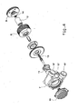
- the device includes a fixed and a movable part.
- the fixed part includes a casing, preferably aluminum alloy casting and plentifully finned to ease cooling, obtained from the assembly of a fluid conveyor 7, a casing of the engine/generator 8 equipped with cooler and a rear cover 9. There is also a front cover with relevant cooler 10.
- the conveyor may be split in two parts to be joined.
- the fluid conveyor 7 includes internally: a converging spiral of the fluid input 15 with relevant inlet 15', a diverging spiral of the fluid output 16 with relevant outlet 16'; a duct 17 and relevant drain plug 17' for recirculation or partial fluid drain.
- the moving part is made of a bladed impeller 11 integral with an engine/generator 12 by means of a steel shaft 13 supported by high speed sealed antifriction bearings, not needing forced lubrication.
- the bearings 14 are mounted at the two ends of the shaft 13 and are inserted in the two covers 9 and 10.
- the bladed impeller is inside the conveyor 7 and works with the inlet 15, the outlet 16 and the duct 17 as follows.
- the device works by means of the fluid dynamic reversibility of the impeller 11 and by means of the engine/generator 12 reversibility (brushless to be preferred), working either as an engine or a generator.
- drain plug 17' can be jointed to a proper choke valve (no.6 in picture 5)
- the device features mechanical fluid reversibility, the ability of handling pressure and capacity, can operate as an autonomous blower and recovers energy otherwise wasted.
- Shape, size and power of the device are accommodated according to its use.
- the engine/generator 12 is a three-phase synchronous electrical machine, with a high efficiency brushless permanent magnet that, operating as an engine, is supplied with a variable high frequency three-phase alternate current obtained converting direct current in an electronic circuit connected to the actuator. As a generator its output is three-phase alternate current rectified by means of silicon diodes.
- Anv available type of rectifying and conversion electronic circuits can be used.
- Benchmark test results are exciting either in compressor or in generator mode.
- An approx. 60 mm impeller and a 2 kg total device weight can develop an electrical power that compares to the one of an average car alternator.
- There is no power loss in the main engine because all the exploited energy comes from the exhaust gas and would have been otherwise wasted through the waste gate or due to the turbo supercharger "variable geometry" system.
- the device subject of the invention can substitute the classic alternator of an ordinary engine, which weights an average 5 to 8 kg resulting in a great improvement in performance, weight and costs.
- the device can be used for many applications.
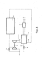
- No. 4 in picture 5 shows a generic engine such as a road trailer internal combustion engine, boosted by turbo supercharger 3 and receiving the exhaust gas coming from the engine 4 equipped with waste gate 5.
- Device 1 subject of the invention, is in series with the turbo supercharger from which it receives the fluid (the compressed air) that is then driven to the inlet 15.
- the outlet 16 supplies the compressed air intake to the engine 4.
- Device 1 is better put after the intercooler, if any.
- Recirculation or partial fluid exhaust duct 17 goes to a special choke valve 6.
- -An electronic converter/rectifier 2 for engine/generator-12 of known type is provided, interfacing as known with the control unit that supervises any other engine function.
- the device subject-matter of the invention is able of filling supercharging gaps that are typical of transient conditions. It "serially” pressurizes the air at the main turbo supercharger (as in two-stage compressors), increasing the torque at low rpm and reducing the grade of smoke due to air shortage. It also reduces the exceeding supercharge pressure delaying the opening of the waste gate and resulting in a greater use of the energy otherwise wasted in exhausted gases.
- the device subject-matter of the invention can be used to restore the power over the full-throttle height. Under this height, being the aviation engine a constant revolution one, it would operate as a supercharge pressure automatic limiter to avoid thermal and mechanical stress of the main engine. In the mean time it operates as main generator; the classic alternator becoming an auxiliary device in a flexible and redundant system. The pressure control would be disabled during take off or in case of emergency.
- the device can also be used with any kind of internal combustion engine (even marine, commercial, two-stroke cycle either Otto engines or diesel engines such as uniflow type engine as separate blower and/or scavenging blower at start up of an hypothetical sealed casing engine) giving clear benefits in terms of ecology, environment and energy consumption, oxygen shortage grade of smoke reduction, as well as benefits due to lesser drawing from the driving shaft thanks to the possibility of reducing or removing the conventional alternator and relevant rather inefficient belt or gear drive.
- any kind of internal combustion engine even marine, commercial, two-stroke cycle either Otto engines or diesel engines such as uniflow type engine as separate blower and/or scavenging blower at start up of an hypothetical sealed casing engine
- the device can act usefully as a compressor to get a slight boost.
- the device can be easily applied to any commercially available engine.
- the device subject-matter of the invention can be applied to any system containing pressurized or moving fluids or to any duct requiring kinetic energy handling of a fluid (gas or liquid) and relevant pressure and/or delivery surging, etc. with small loss of pressure and fast operation time.
- the making of the device may require materials such as stainless steel, titanium o even ceramic in case of corrosive and/or hot fluids.
- Composite materials such as techno polymers fiber reinforced may be used in case of cold fluids.
Landscapes
- Engineering & Computer Science (AREA)
- Mechanical Engineering (AREA)
- General Engineering & Computer Science (AREA)
- Chemical & Material Sciences (AREA)
- Combustion & Propulsion (AREA)
- Chemical Kinetics & Catalysis (AREA)
- General Chemical & Material Sciences (AREA)
- Structures Of Non-Positive Displacement Pumps (AREA)
- Supercharger (AREA)
- Connection Of Motors, Electrical Generators, Mechanical Devices, And The Like (AREA)
- Auxiliary Devices For And Details Of Packaging Control (AREA)
- Compressor (AREA)
- Motor Or Generator Cooling System (AREA)
- Control Of Multiple Motors (AREA)
- Control Of Direct Current Motors (AREA)
- Control Of Electric Motors In General (AREA)
Applications Claiming Priority (3)
| Application Number | Priority Date | Filing Date | Title |
|---|---|---|---|
| IT2002CE000009A ITCE20020009A1 (it) | 2002-09-30 | 2002-09-30 | Dispositivo a girante palettata reversibile con motore/generatore elettrico "senza spazzole" per la gestione dell'aria di sovralimentazione |
| ITCE20020009 | 2002-09-30 | ||
| PCT/IB2003/004311 WO2004029418A1 (en) | 2002-09-30 | 2003-09-30 | Supercharger coupled to a motor/generator unit |
Publications (2)
| Publication Number | Publication Date |
|---|---|
| EP1554467A1 EP1554467A1 (en) | 2005-07-20 |
| EP1554467B1 true EP1554467B1 (en) | 2007-08-15 |
Family
ID=11441096
Family Applications (1)
| Application Number | Title | Priority Date | Filing Date |
|---|---|---|---|
| EP03798347A Expired - Lifetime EP1554467B1 (en) | 2002-09-30 | 2003-09-30 | Supercharger coupled to a motor/generator unit |
Country Status (8)
| Country | Link |
|---|---|
| US (1) | US7382061B2 (it) |
| EP (1) | EP1554467B1 (it) |
| JP (1) | JP4422026B2 (it) |
| AT (1) | ATE370314T1 (it) |
| AU (1) | AU2003264335A1 (it) |
| DE (1) | DE60315688T2 (it) |
| IT (1) | ITCE20020009A1 (it) |
| WO (1) | WO2004029418A1 (it) |
Families Citing this family (18)
| Publication number | Priority date | Publication date | Assignee | Title |
|---|---|---|---|---|
| US7859127B2 (en) * | 2006-06-16 | 2010-12-28 | Tetsuji Tateoka | Generating method and generating system utilizing combustion exhaust gas |
| GB2450957A (en) * | 2007-07-09 | 2009-01-14 | Peter John Bayram | Hybrid power with, or without a battery pack |
| JP2010127239A (ja) * | 2008-11-28 | 2010-06-10 | Mitsubishi Heavy Ind Ltd | 舶用ディーゼル機関 |
| WO2010082893A1 (en) | 2009-01-15 | 2010-07-22 | Volvo Technology Corporation | Electromagnetic, continuously variable transmission power split turbo compound and engine and vehicle comprising such a turbo compound |
| US8253260B2 (en) * | 2009-07-23 | 2012-08-28 | Navistar Canada, Inc. | Exhaust turbine generator system and method of controlling the same |
| US8698333B2 (en) * | 2009-09-23 | 2014-04-15 | Zurn Industries, Llc | Flush valve hydrogenerator |
| PT104972B (pt) * | 2010-02-19 | 2017-10-25 | Inst Superior Tecnico | Turbina com rotor de entrada e saída radiais para aplicações em escoamentos bidireccionados |
| JP5529714B2 (ja) * | 2010-11-12 | 2014-06-25 | 三菱重工業株式会社 | 電動過給機の回転軸支持構造 |
| DE102011018570A1 (de) * | 2011-04-26 | 2012-10-31 | Audi Ag | Anordnung mit Brennkraftmaschine und Turbolader sowie Verfahren zum Betreiben eines Turboladers |
| EP2933459B1 (en) | 2012-12-17 | 2019-02-20 | Kawasaki Jukogyo Kabushiki Kaisha | Engine supercharger |
| US10774730B2 (en) * | 2013-11-12 | 2020-09-15 | Nautilus Engineering, Llc | Systems and methods of forced air induction in internal combustion engines |
| US9325224B2 (en) * | 2013-12-28 | 2016-04-26 | Google Inc. | Electrically-isolated and liquid-cooled rotor and stator assemblies |
| US9083213B1 (en) | 2014-01-09 | 2015-07-14 | Intevep, S.A. | Microgenerator for hydrocarbon producing systems |
| DE102014220677A1 (de) * | 2014-10-13 | 2016-04-14 | Continental Automotive Gmbh | Verfahren zum Betreiben eines Aufladesystems eines Verbrennungsmotors und Verbrennungsmotor mit einem Aufladesystem |
| GB2535617B (en) * | 2015-01-05 | 2020-08-12 | Borgwarner Inc | Electrically driven compressor-expander for a turbocharged engine system and associated flow control valves |
| JP6402646B2 (ja) * | 2015-02-19 | 2018-10-10 | 株式会社豊田自動織機 | 電動過給器 |
| DE102016222520A1 (de) | 2016-11-16 | 2018-05-17 | Robert Bosch Gmbh | Verdichter |
| US10934992B2 (en) * | 2019-02-18 | 2021-03-02 | Toto Ltd. | Hydraulic generator, spouting apparatus, and method for manufacturing hydraulic generator |
Family Cites Families (66)
| Publication number | Priority date | Publication date | Assignee | Title |
|---|---|---|---|---|
| USRE23015E (en) * | 1948-07-06 | Reversible rotary blower | ||
| US2037402A (en) * | 1931-12-07 | 1936-04-14 | Taylor John Leonard | Blower |
| AU113576B2 (en) | 1940-08-07 | 1941-07-30 | Herbert Kranz William | Improvements in and relating to superchargers for engines driven by producer or similar gas |
| US2355494A (en) * | 1941-09-19 | 1944-08-08 | Frank B Yingling | Reversible rotary blower |
| US2453483A (en) * | 1942-12-03 | 1948-11-09 | Frank B Yingling | Electromechanical railroad locomotive |
| US2393852A (en) * | 1943-01-23 | 1946-01-29 | Frank B Yingling | Two-cycle internal-combustion engine |
| US2414187A (en) * | 1943-04-19 | 1947-01-14 | Borsting Erling | Rotary compressor or supercharger |
| US2567636A (en) * | 1947-12-30 | 1951-09-11 | Cuny Andre | Generating set |
| US2724338A (en) * | 1949-05-19 | 1955-11-22 | Roth Co Roy E | Combination centrifugal-turbine pump |
| US2880689A (en) * | 1956-07-25 | 1959-04-07 | Joseph G Bokowski | Flexible drive coupling |
| GB1231397A (it) * | 1967-08-31 | 1971-05-12 | ||
| US3605406A (en) * | 1969-06-27 | 1971-09-20 | Raymond L Woolley | Combined gas and steam power plant |
| US3782850A (en) * | 1971-08-09 | 1974-01-01 | Garrett Corp | Energy transfer machine |
| US3867655A (en) | 1973-11-21 | 1975-02-18 | Entropy Ltd | Shaftless energy conversion device |
| DE2808147A1 (de) * | 1978-02-25 | 1979-08-30 | Martin Bretschneider | Abgasturbolader fuer verbrennungskraftmaschinen |
| DE2823261C2 (de) | 1978-05-27 | 1985-05-23 | Robert Bosch Gmbh, 7000 Stuttgart | Elektrische Maschine |
| FR2504992B1 (fr) | 1981-04-30 | 1986-11-14 | Valbrev | Combinaison d'une turbo-machine de compression ou de detente et d'un moteur electrique |
| EP0210833B1 (en) * | 1985-07-26 | 1991-06-26 | Isuzu Motors Limited | Control system for a supercharged internal combustion engine |
| KR900001291B1 (ko) * | 1985-08-28 | 1990-03-05 | 이스즈지도샤 가부시끼가이샤 | 내연기관의 보조장치 |
| JPS6251723A (ja) * | 1985-08-29 | 1987-03-06 | Isuzu Motors Ltd | 超高速電動−発電機 |
| JPS6251729A (ja) * | 1985-08-30 | 1987-03-06 | Isuzu Motors Ltd | 内燃機関のタ−ボチヤ−ジヤの制御装置 |
| FR2604041B1 (fr) * | 1986-09-11 | 1988-10-28 | Valeo | Procede de commande d'une machine electrique reversible generateur-moteur, pour vehicule automobile, et installation de commande pour la mise en oeuvre d'un tel procede |
| US5065063A (en) | 1988-03-30 | 1991-11-12 | Aisin Seiki Kabushiki Kaisha | Rotating apparatus |
| JP2526100B2 (ja) * | 1988-07-18 | 1996-08-21 | 株式会社 いすゞセラミックス研究所 | 過給機の制御装置 |
| JP2640757B2 (ja) * | 1988-07-18 | 1997-08-13 | 株式会社いすゞセラミックス研究所 | 過給機の制御装置 |
| JPH02241339A (ja) * | 1989-03-14 | 1990-09-26 | Hitachi Ltd | ターボチャージヤ直結回転機用永久磁石回転子 |
| US5140816A (en) * | 1989-05-19 | 1992-08-25 | Natli Enterprises Pty, Ltd. | Internal combustion engine turbo charger |
| US5207063A (en) * | 1991-10-21 | 1993-05-04 | Alliedsignal Inc. | Turbocharger system for internal combustion engine and method of operation |
| GB9417338D0 (en) | 1994-08-25 | 1994-10-19 | Randle James N | Internal combustion engine |
| US5586540A (en) * | 1995-08-29 | 1996-12-24 | Marzec; Steven E. | Multiple stage supercharging system |
| US5577385A (en) | 1995-09-11 | 1996-11-26 | Kapich; Davorin D. | Electropneumatic engine supercharger system |
| US5819524A (en) * | 1996-10-16 | 1998-10-13 | Capstone Turbine Corporation | Gaseous fuel compression and control system and method |
| US5899673A (en) * | 1996-10-16 | 1999-05-04 | Capstone Turbine Corporation | Helical flow compressor/turbine permanent magnet motor/generator |
| US6295974B1 (en) * | 1997-03-21 | 2001-10-02 | Mccants Dale A. | Electric powered compressor for motorcycle engines |
| US6079211A (en) * | 1997-08-14 | 2000-06-27 | Turbodyne Systems, Inc. | Two-stage supercharging systems for internal combustion engines |
| US6202600B1 (en) * | 1998-02-13 | 2001-03-20 | Robert Miceli | Oscillating two stroke internal combustion engine |
| US6082340A (en) * | 1998-03-18 | 2000-07-04 | Heimark; Charles L. | Two-speed supercharger |
| DE19823274C1 (de) | 1998-05-26 | 1999-10-14 | Daimler Chrysler Ag | Abgasturbolader für eine Brennkraftmaschine |
| US6170443B1 (en) * | 1998-09-11 | 2001-01-09 | Edward Mayer Halimi | Internal combustion engine with a single crankshaft and having opposed cylinders with opposed pistons |
| US6324846B1 (en) * | 1999-03-31 | 2001-12-04 | Caterpillar Inc. | Exhaust gas recirculation system for an internal combustion engine |
| US7004115B2 (en) * | 1999-08-31 | 2006-02-28 | Richard Patton | Internal combustion engine with regenerator, hot air ignition, and supercharger-based engine control |
| US6233935B1 (en) * | 1999-12-07 | 2001-05-22 | Ford Global Technologies, Inc. | Method and apparatus for starting an engine having a turbocharger |
| DE10040122A1 (de) | 2000-08-17 | 2002-02-28 | Daimler Chrysler Ag | Abgasturbolader für eine Brennkraftmaschine |
| US6434940B1 (en) * | 2000-09-14 | 2002-08-20 | Albert F. Araujo | Air compressor for charging an internal combustion engine |
| US6450156B1 (en) * | 2000-09-14 | 2002-09-17 | Albert F. Araujo | Turbine supercharger for an internal combustion engine |
| US6709243B1 (en) * | 2000-10-25 | 2004-03-23 | Capstone Turbine Corporation | Rotary machine with reduced axial thrust loads |
| FR2823030B1 (fr) * | 2001-01-31 | 2003-06-20 | Valeo Equip Electr Moteur | Procede de commande d'une machine electrique tournante polyphasee et reversible pour vehicule automobile a moteur thermique |
| JP4560996B2 (ja) | 2001-05-30 | 2010-10-13 | 株式会社Ihi | 容積型過給機を備えた内燃機関 |
| DE60110077T2 (de) * | 2001-10-03 | 2006-03-16 | Visteon Global Technologies, Inc., Dearborn | Steuerung für eine aufgeladene Brennkraftmaschine mit elektronisch geregeltem Ansaugluftverdichter |
| DE60116317T2 (de) * | 2001-10-03 | 2006-07-20 | Visteon Global Technologies, Inc., Dearborn | Steuerung für eine aufgeladene Brennkraftmaschine mit elektronisch geregeltem Ansaugluftverdichter |
| US6755022B2 (en) * | 2002-02-28 | 2004-06-29 | Mack Trucks, Inc. | Turbo-charged internal combustion engine with in-cylinder EGR and injection rate shaping |
| US6938420B2 (en) * | 2002-08-20 | 2005-09-06 | Nissan Motor Co., Ltd. | Supercharger for internal combustion engine |
| FR2843842B1 (fr) * | 2002-08-26 | 2007-02-23 | Valeo Equip Electr Moteur | Dispositif de commande d'une machine electrique tournante pour vehicule |
| JP2004257360A (ja) * | 2003-02-27 | 2004-09-16 | Denso Corp | 二次空気供給システム |
| EP1462629B1 (en) * | 2003-03-27 | 2006-06-14 | Nissan Motor Co., Ltd. | Supercharging device for internal combustion engine |
| JP3951951B2 (ja) * | 2003-04-03 | 2007-08-01 | トヨタ自動車株式会社 | 内燃機関の制御装置 |
| US6718955B1 (en) * | 2003-04-25 | 2004-04-13 | Thomas Geoffrey Knight | Electric supercharger |
| US6931850B2 (en) * | 2003-09-10 | 2005-08-23 | The Regents Of The Univesity Of California | Exhaust gas driven generation of electric power and altitude compensation in vehicles including hybrid electric vehicles |
| US6957632B1 (en) * | 2004-05-20 | 2005-10-25 | Ford Global Technologies, Llc | Air charging system for an opposed piston opposed cylinder free piston engine |
| US6941904B1 (en) * | 2004-06-28 | 2005-09-13 | Ford Global Technologies, Llc | Air scavenging for an opposed piston opposed cylinder free piston engine |
| US7137253B2 (en) * | 2004-09-16 | 2006-11-21 | General Electric Company | Method and apparatus for actively turbocharging an engine |
| TWI242505B (en) * | 2004-12-02 | 2005-11-01 | Jing-Yu Yang | Method and device being able to improve the air-fuel ratio of engine |
| JP2006207417A (ja) * | 2005-01-26 | 2006-08-10 | Denso Corp | 過給機付エンジン制御システム |
| US7047743B1 (en) * | 2005-03-14 | 2006-05-23 | Deere & Company | Electric turbo compound configuration for an engine/electric generator system |
| US7076954B1 (en) * | 2005-03-31 | 2006-07-18 | Caterpillar Inc. | Turbocharger system |
| US20060230759A1 (en) * | 2005-04-13 | 2006-10-19 | Semrau H A | Variable geometry turbocharger |
-
2002
- 2002-09-30 IT IT2002CE000009A patent/ITCE20020009A1/it unknown
-
2003
- 2003-09-30 US US10/529,591 patent/US7382061B2/en not_active Expired - Fee Related
- 2003-09-30 JP JP2004539367A patent/JP4422026B2/ja not_active Expired - Fee Related
- 2003-09-30 WO PCT/IB2003/004311 patent/WO2004029418A1/en not_active Ceased
- 2003-09-30 AT AT03798347T patent/ATE370314T1/de not_active IP Right Cessation
- 2003-09-30 EP EP03798347A patent/EP1554467B1/en not_active Expired - Lifetime
- 2003-09-30 AU AU2003264335A patent/AU2003264335A1/en not_active Abandoned
- 2003-09-30 DE DE60315688T patent/DE60315688T2/de not_active Expired - Lifetime
Non-Patent Citations (1)
| Title |
|---|
| None * |
Also Published As
| Publication number | Publication date |
|---|---|
| DE60315688D1 (de) | 2007-09-27 |
| US7382061B2 (en) | 2008-06-03 |
| JP4422026B2 (ja) | 2010-02-24 |
| AU2003264335A1 (en) | 2004-04-19 |
| US20060091676A1 (en) | 2006-05-04 |
| ATE370314T1 (de) | 2007-09-15 |
| DE60315688T2 (de) | 2008-06-05 |
| WO2004029418A1 (en) | 2004-04-08 |
| ITCE20020009A1 (it) | 2002-12-30 |
| EP1554467A1 (en) | 2005-07-20 |
| JP2006501393A (ja) | 2006-01-12 |
Similar Documents
| Publication | Publication Date | Title |
|---|---|---|
| EP1554467B1 (en) | Supercharger coupled to a motor/generator unit | |
| US5577385A (en) | Electropneumatic engine supercharger system | |
| US5074115A (en) | Turbocharger with rotary electric machine | |
| US20050198957A1 (en) | Turbocompound forced induction system for small engines | |
| EP2229515B1 (en) | Turbocharger arrangement for a piston engine | |
| US4932211A (en) | Internal combustion engine charging unit | |
| ES2014745A6 (es) | Maquina motriz de combustion de pistones sobrealimentada con varios turbo-cargadores de gas de escape, que trabajan en paralelo. | |
| CS209850B2 (en) | Double stage turboblower for the exhaust gases | |
| US5471834A (en) | Engine driven propulsion fan with turbochargers in series | |
| EP2088285A3 (en) | Compound propulsion engine | |
| US20090278360A1 (en) | Generating method and generating system utilizing combustion exhaust gas | |
| CN110500174A (zh) | 一种并联式电动增压系统及其控制方法 | |
| EP0219772B1 (en) | Turbo compound internal combustion engine | |
| US6553764B1 (en) | Enhanced response turbocharger using flywheel storage | |
| CN1175189C (zh) | 大型柴油机增压器组 | |
| US4280797A (en) | Method of controlling the supercharge pressure in an internal-combustion engine, and exhaust-gas turbosupercharger for performing the method | |
| JPS60116821A (ja) | 排気タ−ビン過給機 | |
| JP6655640B2 (ja) | 航空機用レシプロエンジンの過給システム、航空機用レシプロエンジン及び航空機 | |
| EP1625291B1 (en) | Turbo compressor system for an internal combustion engine comprising a compressor of radial type and provides with an impeller with backswept blades | |
| WO1998048157A1 (en) | Turbo charger equipped with sliding member | |
| JP2929329B2 (ja) | ターボコンパウンドエンジン | |
| JPS6019938Y2 (ja) | タ−ボコンパウンドエンジン | |
| JPH09287462A (ja) | エンジンの高過給システム | |
| Bohuslav et al. | Supercharging of High Speed Diesels | |
| CN210122938U (zh) | 电动增压系统及车辆 |
Legal Events
| Date | Code | Title | Description |
|---|---|---|---|
| PUAI | Public reference made under article 153(3) epc to a published international application that has entered the european phase |
Free format text: ORIGINAL CODE: 0009012 |
|
| 17P | Request for examination filed |
Effective date: 20050501 |
|
| AK | Designated contracting states |
Kind code of ref document: A1 Designated state(s): AT BE BG CH CY CZ DE DK EE ES FI FR GB GR HU IE IT LI LU MC NL PT RO SE SI SK TR |
|
| AX | Request for extension of the european patent |
Extension state: AL LT LV MK |
|
| R17P | Request for examination filed (corrected) |
Effective date: 20050429 |
|
| DAX | Request for extension of the european patent (deleted) | ||
| 17Q | First examination report despatched |
Effective date: 20060728 |
|
| GRAP | Despatch of communication of intention to grant a patent |
Free format text: ORIGINAL CODE: EPIDOSNIGR1 |
|
| GRAS | Grant fee paid |
Free format text: ORIGINAL CODE: EPIDOSNIGR3 |
|
| GRAA | (expected) grant |
Free format text: ORIGINAL CODE: 0009210 |
|
| AK | Designated contracting states |
Kind code of ref document: B1 Designated state(s): AT BE BG CH CY CZ DE DK EE ES FI FR GB GR HU IE IT LI LU MC NL PT RO SE SI SK TR |
|
| REG | Reference to a national code |
Ref country code: GB Ref legal event code: FG4D |
|
| REG | Reference to a national code |
Ref country code: CH Ref legal event code: EP |
|
| REG | Reference to a national code |
Ref country code: IE Ref legal event code: FG4D |
|
| REF | Corresponds to: |
Ref document number: 60315688 Country of ref document: DE Date of ref document: 20070927 Kind code of ref document: P |
|
| PG25 | Lapsed in a contracting state [announced via postgrant information from national office to epo] |
Ref country code: BG Free format text: LAPSE BECAUSE OF FAILURE TO SUBMIT A TRANSLATION OF THE DESCRIPTION OR TO PAY THE FEE WITHIN THE PRESCRIBED TIME-LIMIT Effective date: 20071115 Ref country code: ES Free format text: LAPSE BECAUSE OF FAILURE TO SUBMIT A TRANSLATION OF THE DESCRIPTION OR TO PAY THE FEE WITHIN THE PRESCRIBED TIME-LIMIT Effective date: 20071126 Ref country code: NL Free format text: LAPSE BECAUSE OF FAILURE TO SUBMIT A TRANSLATION OF THE DESCRIPTION OR TO PAY THE FEE WITHIN THE PRESCRIBED TIME-LIMIT Effective date: 20070815 Ref country code: FI Free format text: LAPSE BECAUSE OF FAILURE TO SUBMIT A TRANSLATION OF THE DESCRIPTION OR TO PAY THE FEE WITHIN THE PRESCRIBED TIME-LIMIT Effective date: 20070815 |
|
| NLV1 | Nl: lapsed or annulled due to failure to fulfill the requirements of art. 29p and 29m of the patents act | ||
| PG25 | Lapsed in a contracting state [announced via postgrant information from national office to epo] |
Ref country code: AT Free format text: LAPSE BECAUSE OF FAILURE TO SUBMIT A TRANSLATION OF THE DESCRIPTION OR TO PAY THE FEE WITHIN THE PRESCRIBED TIME-LIMIT Effective date: 20070815 Ref country code: LI Free format text: LAPSE BECAUSE OF FAILURE TO SUBMIT A TRANSLATION OF THE DESCRIPTION OR TO PAY THE FEE WITHIN THE PRESCRIBED TIME-LIMIT Effective date: 20070815 Ref country code: CH Free format text: LAPSE BECAUSE OF FAILURE TO SUBMIT A TRANSLATION OF THE DESCRIPTION OR TO PAY THE FEE WITHIN THE PRESCRIBED TIME-LIMIT Effective date: 20070815 |
|
| REG | Reference to a national code |
Ref country code: CH Ref legal event code: PL |
|
| ET | Fr: translation filed | ||
| PG25 | Lapsed in a contracting state [announced via postgrant information from national office to epo] |
Ref country code: BE Free format text: LAPSE BECAUSE OF FAILURE TO SUBMIT A TRANSLATION OF THE DESCRIPTION OR TO PAY THE FEE WITHIN THE PRESCRIBED TIME-LIMIT Effective date: 20070815 |
|
| PG25 | Lapsed in a contracting state [announced via postgrant information from national office to epo] |
Ref country code: DK Free format text: LAPSE BECAUSE OF FAILURE TO SUBMIT A TRANSLATION OF THE DESCRIPTION OR TO PAY THE FEE WITHIN THE PRESCRIBED TIME-LIMIT Effective date: 20070815 Ref country code: MC Free format text: LAPSE BECAUSE OF NON-PAYMENT OF DUE FEES Effective date: 20070930 Ref country code: GR Free format text: LAPSE BECAUSE OF FAILURE TO SUBMIT A TRANSLATION OF THE DESCRIPTION OR TO PAY THE FEE WITHIN THE PRESCRIBED TIME-LIMIT Effective date: 20071116 |
|
| PG25 | Lapsed in a contracting state [announced via postgrant information from national office to epo] |
Ref country code: SK Free format text: LAPSE BECAUSE OF FAILURE TO SUBMIT A TRANSLATION OF THE DESCRIPTION OR TO PAY THE FEE WITHIN THE PRESCRIBED TIME-LIMIT Effective date: 20070815 Ref country code: PT Free format text: LAPSE BECAUSE OF FAILURE TO SUBMIT A TRANSLATION OF THE DESCRIPTION OR TO PAY THE FEE WITHIN THE PRESCRIBED TIME-LIMIT Effective date: 20080115 Ref country code: CZ Free format text: LAPSE BECAUSE OF FAILURE TO SUBMIT A TRANSLATION OF THE DESCRIPTION OR TO PAY THE FEE WITHIN THE PRESCRIBED TIME-LIMIT Effective date: 20070815 |
|
| PLBE | No opposition filed within time limit |
Free format text: ORIGINAL CODE: 0009261 |
|
| STAA | Information on the status of an ep patent application or granted ep patent |
Free format text: STATUS: NO OPPOSITION FILED WITHIN TIME LIMIT |
|
| PG25 | Lapsed in a contracting state [announced via postgrant information from national office to epo] |
Ref country code: SE Free format text: LAPSE BECAUSE OF FAILURE TO SUBMIT A TRANSLATION OF THE DESCRIPTION OR TO PAY THE FEE WITHIN THE PRESCRIBED TIME-LIMIT Effective date: 20071115 Ref country code: RO Free format text: LAPSE BECAUSE OF FAILURE TO SUBMIT A TRANSLATION OF THE DESCRIPTION OR TO PAY THE FEE WITHIN THE PRESCRIBED TIME-LIMIT Effective date: 20070815 |
|
| 26N | No opposition filed |
Effective date: 20080516 |
|
| PG25 | Lapsed in a contracting state [announced via postgrant information from national office to epo] |
Ref country code: IE Free format text: LAPSE BECAUSE OF NON-PAYMENT OF DUE FEES Effective date: 20071001 |
|
| PG25 | Lapsed in a contracting state [announced via postgrant information from national office to epo] |
Ref country code: EE Free format text: LAPSE BECAUSE OF FAILURE TO SUBMIT A TRANSLATION OF THE DESCRIPTION OR TO PAY THE FEE WITHIN THE PRESCRIBED TIME-LIMIT Effective date: 20070815 |
|
| PG25 | Lapsed in a contracting state [announced via postgrant information from national office to epo] |
Ref country code: SI Free format text: LAPSE BECAUSE OF FAILURE TO SUBMIT A TRANSLATION OF THE DESCRIPTION OR TO PAY THE FEE WITHIN THE PRESCRIBED TIME-LIMIT Effective date: 20070815 |
|
| PG25 | Lapsed in a contracting state [announced via postgrant information from national office to epo] |
Ref country code: CY Free format text: LAPSE BECAUSE OF FAILURE TO SUBMIT A TRANSLATION OF THE DESCRIPTION OR TO PAY THE FEE WITHIN THE PRESCRIBED TIME-LIMIT Effective date: 20070815 |
|
| PG25 | Lapsed in a contracting state [announced via postgrant information from national office to epo] |
Ref country code: IT Free format text: LAPSE BECAUSE OF NON-PAYMENT OF DUE FEES Effective date: 20070930 Ref country code: LU Free format text: LAPSE BECAUSE OF NON-PAYMENT OF DUE FEES Effective date: 20070930 |
|
| PG25 | Lapsed in a contracting state [announced via postgrant information from national office to epo] |
Ref country code: HU Free format text: LAPSE BECAUSE OF FAILURE TO SUBMIT A TRANSLATION OF THE DESCRIPTION OR TO PAY THE FEE WITHIN THE PRESCRIBED TIME-LIMIT Effective date: 20080216 Ref country code: TR Free format text: LAPSE BECAUSE OF FAILURE TO SUBMIT A TRANSLATION OF THE DESCRIPTION OR TO PAY THE FEE WITHIN THE PRESCRIBED TIME-LIMIT Effective date: 20070815 |
|
| PGRI | Patent reinstated in contracting state [announced from national office to epo] |
Ref country code: IT Effective date: 20110616 |
|
| REG | Reference to a national code |
Ref country code: FR Ref legal event code: PLFP Year of fee payment: 14 |
|
| REG | Reference to a national code |
Ref country code: FR Ref legal event code: PLFP Year of fee payment: 15 |
|
| PGFP | Annual fee paid to national office [announced via postgrant information from national office to epo] |
Ref country code: FR Payment date: 20170829 Year of fee payment: 15 Ref country code: IT Payment date: 20170828 Year of fee payment: 15 Ref country code: GB Payment date: 20170927 Year of fee payment: 15 |
|
| PGFP | Annual fee paid to national office [announced via postgrant information from national office to epo] |
Ref country code: DE Payment date: 20170927 Year of fee payment: 15 |
|
| REG | Reference to a national code |
Ref country code: DE Ref legal event code: R119 Ref document number: 60315688 Country of ref document: DE |
|
| GBPC | Gb: european patent ceased through non-payment of renewal fee |
Effective date: 20180930 |
|
| PG25 | Lapsed in a contracting state [announced via postgrant information from national office to epo] |
Ref country code: IT Free format text: LAPSE BECAUSE OF NON-PAYMENT OF DUE FEES Effective date: 20180930 Ref country code: DE Free format text: LAPSE BECAUSE OF NON-PAYMENT OF DUE FEES Effective date: 20190402 |
|
| PG25 | Lapsed in a contracting state [announced via postgrant information from national office to epo] |
Ref country code: FR Free format text: LAPSE BECAUSE OF NON-PAYMENT OF DUE FEES Effective date: 20180930 |
|
| PG25 | Lapsed in a contracting state [announced via postgrant information from national office to epo] |
Ref country code: GB Free format text: LAPSE BECAUSE OF NON-PAYMENT OF DUE FEES Effective date: 20180930 |