EP1554514B1 - Clapet anti-retour - Google Patents
Clapet anti-retour Download PDFInfo
- Publication number
- EP1554514B1 EP1554514B1 EP03764408A EP03764408A EP1554514B1 EP 1554514 B1 EP1554514 B1 EP 1554514B1 EP 03764408 A EP03764408 A EP 03764408A EP 03764408 A EP03764408 A EP 03764408A EP 1554514 B1 EP1554514 B1 EP 1554514B1
- Authority
- EP
- European Patent Office
- Prior art keywords
- piston
- unloader
- valve body
- valve
- check valve
- Prior art date
- Legal status (The legal status is an assumption and is not a legal conclusion. Google has not performed a legal analysis and makes no representation as to the accuracy of the status listed.)
- Expired - Lifetime
Links
- 239000000463 material Substances 0.000 claims description 4
- 230000003247 decreasing effect Effects 0.000 claims description 2
- 238000011144 upstream manufacturing Methods 0.000 claims 3
- 238000007789 sealing Methods 0.000 description 13
- 230000006835 compression Effects 0.000 description 9
- 238000007906 compression Methods 0.000 description 9
- 230000001965 increasing effect Effects 0.000 description 7
- 230000009471 action Effects 0.000 description 6
- 230000000694 effects Effects 0.000 description 6
- 239000000314 lubricant Substances 0.000 description 5
- 239000004809 Teflon Substances 0.000 description 4
- 229920006362 Teflon® Polymers 0.000 description 4
- 239000005060 rubber Substances 0.000 description 4
- 230000007246 mechanism Effects 0.000 description 3
- 230000010349 pulsation Effects 0.000 description 3
- 230000002411 adverse Effects 0.000 description 2
- 238000009434 installation Methods 0.000 description 2
- 230000002457 bidirectional effect Effects 0.000 description 1
- 230000002708 enhancing effect Effects 0.000 description 1
- 239000002783 friction material Substances 0.000 description 1
- 230000000977 initiatory effect Effects 0.000 description 1
- 230000004048 modification Effects 0.000 description 1
- 238000012986 modification Methods 0.000 description 1
- 239000004033 plastic Substances 0.000 description 1
- 229920000642 polymer Polymers 0.000 description 1
- 239000012858 resilient material Substances 0.000 description 1
- 230000004044 response Effects 0.000 description 1
Images


Classifications
-
- F—MECHANICAL ENGINEERING; LIGHTING; HEATING; WEAPONS; BLASTING
- F16—ENGINEERING ELEMENTS AND UNITS; GENERAL MEASURES FOR PRODUCING AND MAINTAINING EFFECTIVE FUNCTIONING OF MACHINES OR INSTALLATIONS; THERMAL INSULATION IN GENERAL
- F16K—VALVES; TAPS; COCKS; ACTUATING-FLOATS; DEVICES FOR VENTING OR AERATING
- F16K21/00—Fluid-delivery valves, e.g. self-closing valves
- F16K21/02—Fluid-delivery valves, e.g. self-closing valves providing a continuous small flow
-
- F—MECHANICAL ENGINEERING; LIGHTING; HEATING; WEAPONS; BLASTING
- F04—POSITIVE - DISPLACEMENT MACHINES FOR LIQUIDS; PUMPS FOR LIQUIDS OR ELASTIC FLUIDS
- F04B—POSITIVE-DISPLACEMENT MACHINES FOR LIQUIDS; PUMPS
- F04B49/00—Control, e.g. of pump delivery, or pump pressure of, or safety measures for, machines, pumps, or pumping installations, not otherwise provided for, or of interest apart from, groups F04B1/00 - F04B47/00
- F04B49/02—Stopping, starting, unloading or idling control
- F04B49/03—Stopping, starting, unloading or idling control by means of valves
- F04B49/035—Bypassing
-
- F—MECHANICAL ENGINEERING; LIGHTING; HEATING; WEAPONS; BLASTING
- F16—ENGINEERING ELEMENTS AND UNITS; GENERAL MEASURES FOR PRODUCING AND MAINTAINING EFFECTIVE FUNCTIONING OF MACHINES OR INSTALLATIONS; THERMAL INSULATION IN GENERAL
- F16K—VALVES; TAPS; COCKS; ACTUATING-FLOATS; DEVICES FOR VENTING OR AERATING
- F16K31/00—Actuating devices; Operating means; Releasing devices
- F16K31/12—Actuating devices; Operating means; Releasing devices actuated by fluid
- F16K31/122—Actuating devices; Operating means; Releasing devices actuated by fluid the fluid acting on a piston
- F16K31/1223—Actuating devices; Operating means; Releasing devices actuated by fluid the fluid acting on a piston one side of the piston being acted upon by the circulating fluid
-
- Y—GENERAL TAGGING OF NEW TECHNOLOGICAL DEVELOPMENTS; GENERAL TAGGING OF CROSS-SECTIONAL TECHNOLOGIES SPANNING OVER SEVERAL SECTIONS OF THE IPC; TECHNICAL SUBJECTS COVERED BY FORMER USPC CROSS-REFERENCE ART COLLECTIONS [XRACs] AND DIGESTS
- Y10—TECHNICAL SUBJECTS COVERED BY FORMER USPC
- Y10T—TECHNICAL SUBJECTS COVERED BY FORMER US CLASSIFICATION
- Y10T137/00—Fluid handling
- Y10T137/2496—Self-proportioning or correlating systems
- Y10T137/2559—Self-controlled branched flow systems
- Y10T137/2574—Bypass or relief controlled by main line fluid condition
- Y10T137/2605—Pressure responsive
- Y10T137/2612—Common sensor for both bypass or relief valve and other branch valve
- Y10T137/2615—Bypass or relief valve opens as other branch valve closes
-
- Y—GENERAL TAGGING OF NEW TECHNOLOGICAL DEVELOPMENTS; GENERAL TAGGING OF CROSS-SECTIONAL TECHNOLOGIES SPANNING OVER SEVERAL SECTIONS OF THE IPC; TECHNICAL SUBJECTS COVERED BY FORMER USPC CROSS-REFERENCE ART COLLECTIONS [XRACs] AND DIGESTS
- Y10—TECHNICAL SUBJECTS COVERED BY FORMER USPC
- Y10T—TECHNICAL SUBJECTS COVERED BY FORMER US CLASSIFICATION
- Y10T137/00—Fluid handling
- Y10T137/2496—Self-proportioning or correlating systems
- Y10T137/2559—Self-controlled branched flow systems
- Y10T137/2574—Bypass or relief controlled by main line fluid condition
- Y10T137/2605—Pressure responsive
- Y10T137/2617—Bypass or relief valve biased open
-
- Y—GENERAL TAGGING OF NEW TECHNOLOGICAL DEVELOPMENTS; GENERAL TAGGING OF CROSS-SECTIONAL TECHNOLOGIES SPANNING OVER SEVERAL SECTIONS OF THE IPC; TECHNICAL SUBJECTS COVERED BY FORMER USPC CROSS-REFERENCE ART COLLECTIONS [XRACs] AND DIGESTS
- Y10—TECHNICAL SUBJECTS COVERED BY FORMER USPC
- Y10T—TECHNICAL SUBJECTS COVERED BY FORMER US CLASSIFICATION
- Y10T137/00—Fluid handling
- Y10T137/2496—Self-proportioning or correlating systems
- Y10T137/2559—Self-controlled branched flow systems
- Y10T137/2574—Bypass or relief controlled by main line fluid condition
- Y10T137/2605—Pressure responsive
- Y10T137/2637—Mechanical movement between sensor and valve
-
- Y—GENERAL TAGGING OF NEW TECHNOLOGICAL DEVELOPMENTS; GENERAL TAGGING OF CROSS-SECTIONAL TECHNOLOGIES SPANNING OVER SEVERAL SECTIONS OF THE IPC; TECHNICAL SUBJECTS COVERED BY FORMER USPC CROSS-REFERENCE ART COLLECTIONS [XRACs] AND DIGESTS
- Y10—TECHNICAL SUBJECTS COVERED BY FORMER USPC
- Y10T—TECHNICAL SUBJECTS COVERED BY FORMER US CLASSIFICATION
- Y10T137/00—Fluid handling
- Y10T137/7722—Line condition change responsive valves
- Y10T137/7837—Direct response valves [i.e., check valve type]
- Y10T137/785—With retarder or dashpot
- Y10T137/7852—End of valve moves inside dashpot chamber
Definitions
- An air compressor system is often pressurized with a motor driven compressor controlled by a pressure-operated switch that senses pressure in an air receiver such as a pressure vessel.
- the compressor forces compressed air through a discharge tube and a check valve that is connected to a pressure vessel, the pressure vessel serving as a reservoir for storing the compressed air.
- the pressure switch shuts off the compressor motor to stop further pressurization.
- the lack of pressure from the compressor allows the check valve to close, preventing air from flowing from the air receiver back into the discharge tube when pressurization stops.
- pressurized air may still remain in the discharge tube and in the head of the compressor.
- the pressure switch again operates the compressor to resume pressurization.
- the compressor must overcome the added load from this remaining pressure in addition to the load of initiating pressurization. This can result in adverse system effects on the compressor motor such as motor stalling or electrical circuit overloading in the circuit in which the motor is installed.
- an unloader valve is operated by the pressure switch to relieve the pressure from the discharge tube when the pressure within the pressure vessel rises to a preselected maximum pressure level.
- the unloader valve is connected to the discharge tube through an additional hose, tubing, or other mechanical communication means.
- many air compressors are configured to effect pressurization with compression cylinders or other pulsating mechanisms.
- Such mechanisms effectively establish high pressure conditions within the discharge tube and the head of the compressor to pressurize the pressure vessel.
- the pulsating action of such mechanisms can also lead to pressure pulsations which adversely affect the operation of the check value.
- the check valve incorporates a spring-biased piston assembly
- pressure pulsations from the compressor motor can cause one or more components of the piston assembly to reciprocate in response to the pressure pulsations, possibly leading to undesired vibration and check value damage.
- US 1,850,117 discloses a check value or automatic unloader to be used with air or other gas compressors.
- the bleed valve structure may be readily adjusted from the exterior of the unloader causing it to adjust the period at which the bleed valve commences to open.
- US 4,321,940 discloses an unloader check valve to be installed between a compressor and an air receiver comprising an elongated valve body having an inlet end and an outlet end and a hole extending therethrough from said inlet end to said outlet end; an air bleed aperture extending through said valve body from a location in said hole; and an unloader valve seal reciprocally mounted to move along a path within said hole.
- an unloader check valve as defined above is characterised in that the unloader check valve further comprises a valve seat assembly installed within said hole between said unloader valve seal and said outlet end of said valve body, said valve seat assembly having a circumference and a groove around said circumference, said groove of said valve seat assembly being adjacent said air bleed aperture when said valve seat assembly is installed in said valve body; said valve seat assembly having a plurality of raised unloader seating elements extending toward said inlet end of said valve body and in the path of said unloader valve seal, said unloader seating elements having at least a passage leading from said groove toward said inlet end of said valve body; said valve seat assembly having a check valve seat; a piston assembly mounted within said hole of said valve body, said piston assembly including a piston, a piston spring and a check valve seal, said piston spring normally biasing said piston toward said inlet end of said valve body to a first piston location when the compressor is turned off; said piston assembly having a size and being located at a position within the hole which enables
- a dampener may be attached to the outlet end of the valve body.
- the piston assembly includes a first bumper positioned to remain inside the hole of the valve body. A valve body clearance is maintained between the first bumper and the inside diameter of the hole of the valve body.
- the piston assembly also includes a second bumper positioned to remain inside the inside diameter of the dampener. Together, the first and second bumpers serve to minimize wear on the piston assembly during operation of the check valve.
- the piston assembly further includes a dampener seal which may comprise the second bumper or a separate component and which seals the clearance between the piston assembly and the inside diameter of the dampener.
- a dampener orifice is included with the dampener to restrict the amount of air that can enter the dampener to dampen the movement of the piston.
- check valve seats 37 are darkened in cross sectional views and, depending on the specific embodiment, can comprise separate components or portions of other components, as indicated below and in the several figures.
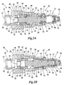
- FIG. 1 is an exploded view depicting the components of an embodiment unloader check valve 20 of the invention.
- the check valve 20 includes an elongated valve body 22 having an inlet end 24 and an outlet end 26.
- the check valve 20 is configured to be interpositioned in an air compressor system between an air compressor (not shown) and pressure vessel (not shown).
- the air compressor is normally connected to the inlet end 24 of the check valve 20 with an inlet line (not shown) connected at inlet threads 25.
- the outlet end 26 of the check valve 20 includes outlet vents 28 that are configured to feed air to the air receiver (not shown) of the pressure vessel, the air receiver being secured to the check valve 20 via outlet threads 27.
- a hexagonal arrangement of tool engagement surfaces 29 allows for the use of a wrench or similar tool for installing the check valve 20 by the inlet threads 25 and outlet threads 27.
- a hole 30 extends through the valve body 22, extending from the inlet end 24 to the outlet end 26 and creating a general path for pressurized air to flow through the valve body 22.
- a valve seat assembly 32 is positioned within the hole 30 adjacent an air bleed aperture 34, the air bleed aperture 34 extending from the hole 30 to the exterior 36 of the valve body 22.
- the valve seat assembly 32 can be compression fitted into position within the hole 30 by inserting the valve seat assembly 32 through the outlet end 26 of the valve body 22 after the installation of an unloader valve seal 46 and prior to the installation of other components.
- the valve seat assembly 32 rests against a fitting ridge 35 within the hole 30 of the valve body 22.
- the valve seat assembly 32 includes a check valve seat 37 which is positioned on the side of the valve seat assembly 32 that is nearest the outlet end 26 of the valve body 22.
- the check valve seat 37 can, in some embodiments, comprise a separate washer component 39 that is then coupled to the rest of the valve seat assembly 32.
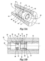
- the valve seat assembly 32 is depicted alone in FIGS. 14A-D. As shown, a groove 38 extends around the circumference of the valve seat assembly 32.
- the valve seat assembly 32 is shown installed in a hole 30 of a valve body 22 in FIGS.13A and 13B. When installed in the valve body 22, the valve seat assembly 32 is positioned so that the groove 38 is adjacent the air bleed aperture 34.
- the valve seat assembly 32 includes a number of raised unloader seating elements 40 which extend from the valve seat assembly 32 toward the inlet end 24 of the valve body 22.
- An air passage 42 extends from each seating element 40 into the valve seat assembly 32.
- the groove 38 has a separate notch portion 44 leading to each air passage 42 which allows the communication of air between each air passage 42 and the air bleed aperture 34.
- an unloader valve seal 46 is reciprocally positioned within the hole 30 of the valve body 22 between the inlet end 24 of the valve body 22 and the valve seat assembly 32.
- the unloader valve seal 46 can be constructed of rubber, plastic, Teflon, or other similar resilient material to minimize wear against the inside surfaces of the hole 30 of the valve body 22 while providing an adequate seal.
- the diameter of the unloader valve seal 46 is sufficiently small to allow a pressure discharge gap 48 to exist between the unloader valve seal 46 and the inside diameter of the hole 30 of the valve body 22.
- the pressure discharge gap 48 permits the unloader valve seal 46 to reciprocate in directions that are toward the inlet end 24 of the valve body 22 and away from the inlet end 24, that is toward the valve seat assembly 32.
- the unloader valve seal 46 also includes a pressure hole 49 lined with an engagement collar 50 that extends approximately through the center of the unloader valve seal 46.
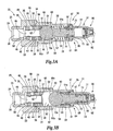
- a piston assembly 52 is constructed around a piston 54 which is biased to a first piston location (as shown in FIG. 2A) with a piston spring 55.
- the piston spring 55 is configured to exert compression forces between a spring seat 51 and a disk portion 58 of the piston 54.
- the arrangement of the piston spring 55 and spring seat 51 can vary considerably within the contemplated scope of the invention.
- the spring seat 51 is shown as being integral to a first end 84 of a dampener 31.
- a washer, snap ring or other seating element can be used.
- the piston spring 55 can also be positioned either partially or entirely outside of the valve body 22.
- the piston spring 55a is compressed between a disk portion 58 and spring seat 51 a contained within the dampener 31.
- Other configurations of the piston spring 55 are also possible.
- the piston 54 when in the first piston location, the piston 54 extends through a piston hole 56 in the valve seat assembly 32 to contact the engagement collar 50 of the unloader valve seal 46. In contacting the engagement collar 50, the piston 54 holds the unloader valve seal 46 away from the seating elements 40 of the valve seat assembly 32. This leaves the air passages 42 of the seating elements 40 unobstructed. As a result, air pressure residing within the air inlet line is free to escape through the inlet end 24 of the valve body 22, through the pressure discharge gap 48 between the unloader valve seal 46 and inside surface of the hole 30.
- Air pressure can then continue to escape through air passages 42 of the seating elements 40 to the groove 38 of the valve seat assembly 32, and finally through the air bleed aperture 34 of the valve body 22 to the environment.
- This release of air pressure from the valve body 22 significantly reduces the amount of back pressure in the inlet line and valve body 22 that the compressor must work against at the start of operation.
- the compressor After the start of operation of the compressor, it is desirable to restrict air pressure from escaping from within the valve body 22 so that the full magnitude of pressure within the inlet line is directed through the outlet vents 28 and toward the pressure vessel.
- the air pressure in the air receiver increases.
- the magnitude of pressure flowing from the inlet line into the inlet end 24 of the valve body 22 will generally be sufficient to force the piston 54 to compress the piston spring 55 and to move to one of a plurality of piston locations that are each downstream and further away from the inlet end 24 of the valve body 22 than the first piston location.
- An example of one such downstream piston location is the location of the piston 54 depicted in FIG. 2B.
- the exact location to which the piston 54 moves generally depends on the magnitude of air pressure flowing from the compressor into the inlet end 24 of the valve body 22.
- valve seat assembly 32 As shown in FIG. 2B, as increased air pressure within the valve body 22 forces the piston 54 to a downstream piston location, the piston 54 no longer restricts movement of the unloader valve seal 46 away from the inlet end 24 of the valve body 22 toward the valve seat assembly 32. Air flowing from the inlet end 24 toward the outlet end 26 of the valve body 22 also forces the unloader valve seal 46 to move toward and contact the unloader seating elements 40 of the valve seat assembly 32, sealing the air passage 42 of each seating element 40 from the hole 30 of the valve body 22. As shown in FIG. 2B and in FIGS. 14 A-D, some embodiments of the valve seat assembly 32 include three approximately equidistantly spaced seating elements 40 to allow for a three-point contact effect which tends to improve the overall effectiveness of the seal. Terminating the flow of air between the hole 30 and air bleed aperture 34 thus maximizes the amount of air pressure within the inlet line that is directed through the outlet vents 28.
- the piston assembly 52 when the compressor is not operating and the piston 54 is in a first position, the piston assembly 52 includes a check valve seal 60 positioned to seal against the check valve seat 37 and thereby seal the inlet line from the air compressor from the pressure vessel. The sealing action of the check valve seal 60 then allows the valve seat assembly 32 and air bleed aperture 34 to remove back pressure from the inlet line without draining pressure from the pressure vessel.
- the hole 30 extending through the valve body 22 includes a tapered portion 64 having a first inner diameter 66 and a larger second inner diameter 68, the first inner diameter 66 being closer to the inlet end 24 of the valve body 22 than is the second inner diameter 68. Due to this configuration, the clearance space 62 between the check valve seal 60 and valve body 22 is greater when the piston 54 is at a downstream piston location that is farther away from the inlet end 24 of the valve body 22 than when the piston 54 is at a downstream piston location that is closer to the inlet end 24 of the valve body 22.
- the level of air that is permitted to flow through the check valve 20 is greater when the piston 54 is at a downstream piston location that is further away from the inlet end 24 of the valve body 22 than when the piston 54 is at a downstream piston location that is closer to the inlet end 24 of the valve body 22.
- This tapered valve body allows the check valve to be used with air compressors having different volume output levels.
- the volume output level of the air pressure produced may be subject to cyclical fluctuations due to the reciprocal operation of mechanical components within each compressor. When connected to a check valve 20 of the invention, these fluctuations will tend to cause reciprocation of the piston 54 to various positions within the hole 30 of the valve body 20.
- a dampener 31 having a first end 84 and second end 86 is attached to the outlet end 26 of the valve body 20.
- the first end 84 of the dampener 31 is open to the outlet end 26 of the valve body 20 to permit the piston assembly 52 to extend into and remain inside the dampener 31 during operation.
- a dampener bumper 88 is positioned near the second end 86 of the dampener 31 to restrict movement of the piston assembly 52 when the piston 54 is moved to a downstream position that is furthest away from the inlet end 24 end of the valve body 22 (as shown in FIG. 2B) and to cushion contact between the piston assembly and the second end 86 of the dampener 31.
- the dampener 31 can be affixed to the outlet end 26 of the valve body 22 in a variety of ways.
- the first end 84 of the dampener 31 includes a dampener flange 87 that is integral to the structure of the dampener and which is inserted into the outlet end 26 of the valve body 22.
- the valve body 22 includes a formable shoulder 89 which can be spun inwardly with a lathe or other radial positioning tool to form the shoulder 89 so that it engages the dampener flange 87 to lock the valve body 22 into position.
- the dampener flange 87 can also form the spring seat 51. Similar shoulder arrangements are shown in FIGS. 3A and B, 8 and 10.
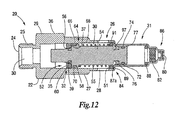
- FIG.11 an embodiment of the unloader check valve 20 is shown that is similar to the embodiment of FIGS. 2A and B except for the addition of a mounting washer 91 that is positioned within the hole 30 and near the inlet end 24 to the valve body 22.
- the mounting washer 91 can also serve as the spring seat 51 in this embodiment.
- a flared dampener flange 87a is inserted into the outlet end 26 to rest against the mounting washer 91.
- the formable shoulder 89 is then formed inwardly to lock the dampener 31 in position. Similar shoulder arrangements are shown in FIGS. 4A and B, 5A and B and 12.
- a mounting washer 91 b can include a relief section 93 at the spring seat 51 to accommodate and position the piston spring 55. Referring briefly to FIG. 9, a mounting washer 91 b having an extended spring seat 51b and an integral dampener lange 87b.
- the piston assembly 52 includes a first bumper 70 which is positioned to remain within the hole 30 of the valve body 22 to minimize wear from reciprocating or vibrational contact with the valve body 22. Wear from such contact can be further reduced with the addition of a lubricant between the first bumper 70 and valve body 22. Notwithstanding such contact, FIGS. 2A and 2B depict how the first bumper 70 still permits a sufficient amount of clearance with the valve body 22 to allow air pressure to flow between the check valve seal 60 and the outlet vents 28. Also as shown, the first bumper 70 can comprise a rubber o-ring or other elastic element which can, in some embodiments, be mounted on the disk portion 58 of the piston 54.
- the piston assembly 52 also includes a second bumper 72 which is positioned to remain within the dampener 31 to minimize wear from reciprocating or vibrational contact with the dampener 31. As with the first bumper 70, wear from such contact between the second bumper 72 and dampener 31 can be further reduced with the addition of a lubricant.
- FIGS. 15A and B show magnified views of the piston assembly 52 and dampener 31 of FIGS. 2A and B.
- FIG. 15A depicts the piston assembly 52 as the piston 54 moves away from the inlet end 24 of the valve body 22
- FIG. 15B depicts the piston assembly 52 as the piston 54 moves toward the inlet end 24 of the valve body 22.
- the second bumper 72 of the piston assembly 52 allows a sufficient second bumper clearance 74 from the inside diameter of the dampener 31 to permit air to freely pass by the second bumper 72 as the piston 54 moves away from and then toward the inlet end 24 of the valve body 22.
- the piston assembly 52 of the depicted embodiment includes a dampener seal 76 having a c-shaped cross section.
- a dampener seal 76 that is unidirectional in the form of a lip seal o-ring, it will be appreciated that other dampener seal configurations, including other unidirectional seal configurations, are also possible and are contemplated to be within the scope of the invention.
- the depicted dampener seal 76 is configured to bend inwardly across its cross section under the force of passing air as the piston 54 moves away from the inlet end 24 of the valve body 22, allowing a seal clearance 78 with the inside surface of the dampener 31.
- air flow is not substantially impeded, preventing substantial compression of air within the dampener 31.
- significant dampening action does not occur as the piston 54 moves away from the inlet end 24 of the valve body 22 and toward the closed end of dampener 31.
- the dampener 31 further includes a narrow dampener orifice 80 and air filter 82, which in the illustrated embodiment, are positioned near the second end 86 of the dampener 31.
- a narrow dampener orifice 80 and air filter 82 which in the illustrated embodiment, are positioned near the second end 86 of the dampener 31.
- FIGS. 2A and B and FIGS. 15A and B each include a second bumper 72 for reducing vibrational wear
- certain embodiments may omit the second bumper 72 and/or use the unidirectional seal 76 to perform a vibrational wear reducing function.
- a piston assembly 52 is shown in which no second bumper is present.
- the unidirectional seal 76 performs both sealing and vibrational wear reducing functions.
- An additional lubricant may also be added to the dampener 31 to further reduce vibrational wear.
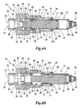
- FIGS. 3A and B show an embodiment of the unloader check valve 20 in which the piston assembly 52 includes a ball 90 configured to serve as both a check valve seal 60a and first bumper 70a, the ball 90 being positioned to contact and seal against the check valve seat 37 when the piston 54a is in the first piston location and being further positioned to extend to prevent virbrational contact between the piston 54a and inside surface of the hole 30.
- the ball 90 can comprise rubber, Teflon, or other suitable material for sealing and for minimizing wear and vibrational contact between the valve body 22 and piston 54.
- an unloader sleeve 92 is reciprocally positioned to extend between the ball 90 and unloader valve seal 46 when the piston 54a is in the first position (as shown in FIG. 3A).
- the unloader sleeve 92 can be integral to the engagement collar 50 of the unloader valve seal 46 and can be configured to make contact with the ball 90 while the piston 54a is in the first piston location. In this position, the unloader sleeve 92 holds the unloader valve seal 46 away from the unloader seating elements 40 of the valve seat assembly 32. This allows air pressure to flow from the inlet end 24 of the valve body 22 to the air bleed aperture 34 while the ball 90 maintains air pressure within the pressure vessel by contacting check valve seat 37 and sealing the inlet end 24 of the valve body 22 from the outlet vents 28.
- the check valve seal 60 can also comprise the first bumper 70.
- the first bumper 70 is configured to remove clearance with the valve body 22 when the piston 54 is in the first piston location (as shown in FIG. 4A), thereby sealing the inlet end 24 from the outlet end 26 of the valve body 22.
- FIG. 4B when the compressor is turned on to increase air pressure and force the piston 54 to a downstream piston location, clearance is restored between the check valve seal 60 and valve body 22 due to the tapered portion 64 of the hole 30 extending through the valve body 22.
- FIGS. 4A and 4B also demonstrates how the piston assembly 52 can be modified to incorporate a dampener seal 76a that is a bidirectional seal and to eliminate the need for a second bumper 72.
- the dampener seal 76a comprises a flexible o-ring which extends the width of the cylinder clearance 77 so that no seal clearance exists between the piston assembly 52 and dampener 31.
- the dampener seal 76a can comprise a material which is appropriate to minimize vibrational wear between the dampener 31 and piston assembly 52 and which may be combined with a lubricant to reduce friction during operation.
- the dampener seal 76a eliminates seal clearance regardless of the direction in which the dampener seal 76a moves.
- this embodiment permits dampening action to occur when the piston 54 moves both toward and away from the inlet end 24 of the valve body 22.
- An additional lubricant may also be added to the dampener 31 to further reduce vibrational wear.
- some embodiments can incorporate a second bumper 76b which can be a combination of a rubber or polymer compression ring 94 and a seal ring 96.
- the seal ring 96 comprises an extremely low-friction material such as Teflon.
- Teflon an extremely low-friction material
- the compression ring 94 is positioned on the piston assembly 52 inside of the Teflon ring 96 within a dampener groove 97. The seal ring 96 is then compressed by the compression ring 94 between the piston assembly 52 and inside surface of the dampener 31.
- the material composition of the seal ring 96 tends to greatly reduce friction with the dampener 31 while the compression forces of the compression ring 94 against the piston assembly 52 and dampener 31 tend to preserve the shape of the seal ring 96, enhancing the sealing effect of the seal ring 96. Due to the constant sealing of the seal ring 96, dampening action occurs when the piston 54 moves both toward and away from the inlet end 24 of the valve body 22.
- FIGS. 5A and B depict an unloader check valve 20 according to the invention having a trip check valve 98 in the air bleed aperture 34.
- the air bleed aperture 34a extends from the hole 30 to the environment of the valve body 22, the air bleed aperture 34a having a bleed chamber 100 in which a bleeder rod assembly 102 and sealing surface 104 of the trip check valve 98 are contained.
- the bleeder rod assembly 102 includes a bleeder disk 106 and bleeder rod 108, the bleeder rod 108 being connected to the bleeder disk 106 and extending from the bleeder disk 106 into the hole 30 of the valve body 22. As best understood by comparing FIG. 5A with FIG. 5B, there is generally sufficient space within the bleed chamber 100 to permit the bleeder rod assembly 102 to pivot about the bleeder disk 106.
- the piston assembly 52 is configured to contact the bleeder rod 108 when the piston 52 is in the first piston location, as shown. This forces the bleeder rod assembly 102 to pivot to an orientation in which the bleeder disk 106 partially pulls away from the sealing surface 104 of the bleed chamber 100 to provide an opening through the air bleed aperture 34. This also permits air pressure to exit from the inlet end 24 of the valve body 22 as the piston assembly 52 seals the pressure vessel from the inlet end of the valve body 22.
- the piston assembly 52 is depicted after the air compressor has been turned on to add air pressure to the inlet end 24 of the valve body 22.
- the increased air pressure forces the piston 54 to move to a downstream position so that the piston 54 no longer makes contact with the bleeder rod 108.
- the increased air pressure also pushes against the bleeder disk 106 inside the bleed chamber 100. Since the piston assembly 52 no longer restricts the movement of the bleeder rod 108, the bleeder disk 106 is free to pivot under the force of the increased air pressure to enable the bleeder disk 106 to seal against the sealing surface 104 of the bleed chamber 100.
- the sealing surface 104 can include a gasket 110 to improve this sealing effect.
- the hole 30 extending through the valve body 22 follows a non-linear axis with the air bleed aperture 34b having a stem check valve 112 in a bleed chamber 100.
- the stem check valve 112 has a stem spring seat 114 and a stem seat 116.
- a stem assembly 118 includes a stem head 120, stem seal 122, stem rod 124, and stem spring 126.
- the stem head 120, stem seal 122 and stem spring 126 are positioned within the bleed chamber 100, while the stem rod 124 extends from the stem head 120 into the hole 30 of the valve body 22.
- the stem spring 126 is positioned between the stem head 120 and stem spring seat 114 to bias the stem seal 122 to seal against the stem seat 116.
- the piston assembly 52 contacts the stem rod 124, pushing the stem assembly 118 in a direction that is away from the outlet end 26 of the valve body 22.
- the piston assembly 52 is depicted with the piston 54 in a downstream position after the compressor begins to add air pressure through the inlet end 24 of the valve body 22.
- the piston assembly 52 no longer restricts movement of the stem rod 124.
- the spring force of the stem spring 126 is greater in proportion to the compressible surface area of the stem rod 124 than is the spring force of the piston spring 55 in proportion to the compressible surface area of the piston assembly 52.
- the force of the air pressure from the compressor is normally not sufficient to overcome the force of the stem spring 126. This permits the stem spring 126 to force the stem seal 122 against the stem seat 116 and close the stem check valve 112.
- piston assembly 52 that includes a piston 54 comprising a single component that extends into the dampener 31, it will be further appreciated that the piston assembly 52 can be constructed so that other components extend into the dampener 31 or into other areas of the unloader check valve 20.
- the depicted piston assembly 52 includes an extension 128 connected to the piston 54 so that the extension 128 remains inside the dampener 31 during the operation of the check valve 20.
- the extension 128 can be fastened to the piston 54 with a wedged, riveted, welded or other appropriately connected fitting.
Landscapes
- Engineering & Computer Science (AREA)
- General Engineering & Computer Science (AREA)
- Mechanical Engineering (AREA)
- Compressor (AREA)
- Check Valves (AREA)
- Valve-Gear Or Valve Arrangements (AREA)
- Safety Valves (AREA)
Claims (19)
- Clapet antiretour de marche à vide (20) à installer entre un compresseur et un réservoir d'air comprimé comprenant un corps de clapet allongé (22) ayant une entrée (24) et une extrémité de sortie (26) et un orifice (30) s'étendant au travers de celui-ci de ladite extrémité d'entrée (24) jusqu'à ladite extrémité de sortie (26) ; une ouverture de purge d'air (34) s'étendant au travers dudit corps de clapet (22) à partir d'une localisation dans ledit orifice (30) ; et un joint de clapet de marche à vide (46) monté réciproquement pour se déplacer le long d'une voie dans ledit orifice ; caractérisé en ce que le clapet antiretour de marche à vide comprend en outre :un ensemble de siège de clapet (32) installé dans ledit orifice (30) entre ledit joint de clapet de marche à vide (46) et ladite extrémité de sortie (26) dudit corps de clapet (22), ledit ensemble de siège de clapet (32) ayant une circonférence et une rainure (38) autour de ladite circonférence, ladite rainure (38) dudit ensemble de siège de clapet (32) étant adjacente à ladite ouverture de purge d'air (34) lorsque ledit ensemble de siège de clapet (32) est installé dans ledit corps de clapet (22) ;ledit ensemble de siège de clapet (32) ayant une pluralité d'éléments de portée de marche à vide relevés (40) s'étendant vers ladite extrémité d'entrée (24) dudit corps de clapet (22) et dans la voie dudit siège de clapet de marche à vide (46), lesdits éléments de portée de marche à vide (40) ayant au moins un passage (42) menant de ladite rainure (38) vers ladite extrémité d'entrée (24) dudit corps de clapet (22) ;ledit ensemble de siège de clapet (32) ayant un siège de clapet antiretour (37) ;un ensemble de piston (52) monté dans ledit orifice (30) dudit corps de clapet (22), ledit ensemble de piston (52) comprenant un piston (54), un ressort de piston (55) et un joint de clapet antiretour (60), ledit ressort de piston (55) inclinant normalement ledit piston (54) vers ladite extrémité d'entrée (24) dudit corps de clapet (22) jusqu'à un premier emplacement de piston lorsque le compresseur est éteint ;ledit ensemble de piston (52) ayant une taille et étant localisé à une position dans l'orifice (30) qui lui permet d'éloigner ledit joint de clapet de marche à vide (46) desdits éléments de portée (40) lorsque ledit piston (54) se trouve au premier emplacement de piston, ledit joint de clapet antiretour (60) étant positionné de sorte à venir en contact avec ledit siège de clapet antiretour (37) lorsque ledit piston (54) se trouve au premier emplacement de piston ;ledit clapet antiretour de marche à vide (20) permettant à l'air de circuler d'entre ledit joint de clapet de marche à vide (46) et ledit ensemble de siège de clapet (32) par ledit au moins un passage (42) desdits éléments de portée de marche à vide (40) jusqu'à ladite rainure (38) dudit ensemble de siège de clapet (32) et permettant à l'air de sortir dudit clapet antiretour de marche à vide (20) par ladite ouverture de purge d'air (34) lorsque ledit ensemble de piston (52) tient ledit joint de clapet de marche à vide (46) loin desdits éléments de portée de marche à vide (40) ;ledit piston (54) étant déplaçable du premier emplacement de piston vers au moins un emplacement de piston en aval plus éloigné de ladite extrémité d'entrée (24) dudit corps de clapet (22) que le premier emplacement de piston lorsque le compresseur est allumé pour accroître la pression dans le réservoir d'air comprimé ;ledit ensemble de piston (52) permettant audit joint de clapet de marche à vide (46) de se déplacer vers, et de venir en contact avec, lesdits éléments de portée de marche à vide (40) lorsque ledit piston (54) se déplace vers un des emplacements de piston en aval, évitant ainsi à l'air de passer de ladite extrémité d'entrée (24) dudit corps (22) à ladite ouverture de purge d'air (34) lorsque ledit piston (54) se trouve à l'un des emplacements de piston en aval ;ledit piston (54) étant déplaçable vers le premier emplacement de piston par ledit ressort de piston (55) lorsque ledit compresseur d'air pulse des quantités décroissantes d'air du compresseur d'air vers le réservoir d'air comprimé.
- Clapet antiretour de marche à vide (20) selon la revendication 1 comprenant un humecteur (31) connecté audit corps de clapet (22), ledit humecteur (31) étant configuré pour humidifier le mouvement dudit piston (54), dans lequel ledit humecteur (31) comprend un cylindre humecteur ayant une première extrémité (84), une seconde extrémité (86), et un diamètre intérieur, ladite première extrémité dudit cylindre humecteur étant positionnée à l'extrémité de sortie (26) dudit corps de clapet (20), ladite seconde extrémité (86) dudit cylindre humecteur ayant un orifice humecteur (80) au travers de celui-ci, ledit ensemble de piston (52) s'étendant dans ledit cylindre humecteur lorsque ledit piston (54) se trouve au premier emplacement de piston.
- Clapet antiretour de marche à vide (20) selon la revendication 1 comprenant un humecteur (31) connecté audit corps de clapet (22), ledit humecteur (31) étant configuré pour humidifier le mouvement dudit piston (54), dans lequel ledit humecteur (31) comprend en outre :un cylindre humecteur (31) ayant une première extrémité (84), une seconde extrémité (86), et un diamètre intérieur, ladite première extrémité (84) dudit cylindre humecteur étant positionnée à l'extrémité de sortie (26) dudit corps de clapet (20), ladite seconde extrémité (86) dudit cylindre humecteur ayant un orifice humecteur (80) au travers de celui-ci ;ledit ensemble de piston (52) s'étendant dans ledit cylindre humecteur (31) lorsque ledit piston (54) se trouve au premier emplacement de piston ;
un joint unidirectionnel (76) positionné pour permettre à l'air de circuler entre ledit diamètre intérieur dudit cylindre humecteur (31) et ledit ensemble de piston (52) lorsque ledit piston (54) se déplace vers ladite extrémité de sortie (26) dudit corps de clapet (20) ; ledit joint unidirectionnel (76) étant également positionné pour empêcher l'air de circuler entre ledit diamètre intérieur dudit cylindre humecteur (31) et ledit ensemble de piston (52) lorsque ledit piston s'éloigne de ladite extrémité de sortie (26) du corps de clapet (20). - Clapet antiretour de marche à vide (20) selon la revendication 1 comprenant un humecteur (31) connecté audit corps de clapet (22), ledit humecteur (31) étant configuré pour humidifier le déplacement dudit piston (54), dans lequel ledit humecteur (31) comprend en outre :un cylindre humecteur (31) ayant une première extrémité (84), une seconde extrémité (86), et un diamètre intérieur, ladite première extrémité (84) dudit cylindre humecteur (31) étant positionnée à l'extrémité de sortie (26) dudit corps de clapet (20), ladite seconde extrémité (86) dudit cylindre humecteur (31) ayant un orifice humecteur (80) au travers de celui-ci ;ledit ensemble de piston (52) s'étendant dans ledit cylindre humecteur (31) lorsque ledit piston (54) se trouve au premier emplacement de piston ;un joint torique (76) positionné pour empêcher l'air de circuler entre ledit diamètre intérieur dudit cylindre humecteur (31) et ledit ensemble de piston (52) lorsque ledit piston (54) se déplace vers ladite extrémité de sortie (26) dudit corps de clapet (20) ; ledit joint torique (76) étant également positionné pour empêcher l'air de circuler entre ledit diamètre intérieur dudit cylindre humecteur (31) et ledit ensemble de piston (52) lorsque ledit piston (54) s'éloigne de ladite extrémité de sortie (26) du corps de clapet (20).
- Clapet antiretour de marche à vide (20) selon l'une des revendications précédentes, ledit joint de clapet antiretour (60) comprenant un joint torique monté sur ledit piston (54).
- Clapet antiretour de marche à vide (20) selon l'une des revendications précédentes, ledit ensemble de piston (52) contenant une bille (90) positionnée pour avoir un mouvement alternatif avec ledit piston (54) et pour comprendre ledit joint de clapet antiretour, ladite bille (90) venant en contact avec ledit siège de clapet antiretour (37) lorsque ledit piston (54) se trouve au premier emplacement de piston.
- Clapet antiretour de marche à vide (20) selon l'une des revendications précédentes, ledit ensemble de piston (52) contenant un amortisseur (70) monté sur ledit piston (54) entre ledit ensemble de siège de clapet (32) et ladite extrémité de sortie (26) dudit corps de clapet (22), ledit amortisseur (70) ayant une taille qui permet une quantité suffisante de dégagement avec ledit corps (22) pour permettre à la pression d'air de circuler dudit joint de clapet antiretour (60) à ladite extrémité de sortie (26) dudit corps de clapet (22) lorsque ledit piston (54) se trouve à l'emplacement qui est en aval du premier emplacement de piston.
- Clapet antiretour de marche à vide (20) selon l'une des revendications 1 à 7, ledit ensemble de piston (52) contenant un premier amortisseur (70) comprenant un joint torique monté sur ledit piston (54) entre ledit ensemble de siège de clapet (32) et ladite extrémité de sortie (26) dudit corps de clapet (22), ledit amortisseur (70) ayant une taille qui permet une quantité suffisante de dégagement avec ledit corps de clapet (22) pour permettre à la pression d'air de circuler dudit joint de clapet antiretour (60) jusqu'à ladite extrémité de sortie (26) dudit corps de clapet (22).
- Clapet antiretour de marche à vide (20) selon l'une des revendications 1 à 5, ledit ensemble de piston (52) contenant un premier amortisseur (70) comprenant une bille positionnée pour avoir un mouvement alternatif avec ledit piston (54), ledit amortisseur (70) ayant une taille qui permet une quantité suffisante de dégagement avec ledit corps de clapet (22) pour permettre à la pression d'air de circuler dudit joint de clapet antiretour (60) jusqu'à ladite extrémité de sortie (26) dudit corps de clapet (22).
- Clapet antiretour de marche à vide (20) selon l'une des revendications 1 à 5, ledit ensemble de piston (52) contenant une bille (90) positionnée pour avoir un mouvement alternatif avec ledit piston (54), ladite bille (60) comprenant un joint de clapet antiretour (90) et venant en contact avec ledit siège de clapet antiretour (37) lorsque ledit piston (54) se trouve au premier emplacement de piston, ladite bille (90) comprenant en outre un premier amortisseur (70) ayant une taille qui permet une quantité suffisante de dégagement avec ledit corps de clapet (22) pour permettre à la pression d'air de circuler dudit joint de clapet antiretour (90) jusqu'à ladite extrémité de sortie (26) dudit corps de clapet (22).
- Clapet antiretour de marche à vide (20) selon l'une des revendications précédentes, ladite pluralité d'éléments de portée de marche à vide relevés (4) comprenant trois éléments de portée (40) espacés approximativement de façon équidistante.
- Clapet antiretour de marche à vide (20) selon l'une des revendications 1 à 10, ladite pluralité d'éléments de portée de marche à vide relevés (40) comprenant trois éléments de portée (40) espacés approximativement de façon équidistante, chacun desdits éléments de portée de marche à vide (40) ayant un dit passage (42) menant de ladite rainure (38) à ladite extrémité d'entrée (24) dudit corps de clapet (22).
- Clapet antiretour de marche à vide (20) selon l'une des revendications précédentes, ledit joint de clapet de marche à vide (46) comprenant un matériau qui est suffisamment élastique pour permettre aux-dits éléments de portée de marche à vide (40) d'imprimer un joint contre ledit joint de clapet de marche à vide (46) lorsque ledit joint de clapet de marche à vide (46) vient en contact avec lesdits éléments de portée de marche à vide (40).
- Clapet antiretour de marche à vide (20) selon l'une des revendications précédentes, ledit ensemble de siège de clapet (32) contenant un orifice de piston (56) au travers duquel ledit ensemble de piston (52) s'étend pour venir au contact dudit joint de clapet de marche à vide (46) lorsque ledit piston (54) se trouve au premier emplacement de piston, ledit orifice de piston (56) permettant à l'air de circuler de ladite extrémité d'entrée (24) dudit corps de clapet vers ladite extrémité de sortie (26) dudit corps de clapet (22) lorsque ledit piston (54) se trouve à un emplacement de piston en aval.
- Clapet antiretour de marche à vide (20) selon l'une des revendications 1 à 13, ledit joint de clapet de marche à vide (46) comprenant un orifice de piston (49) au travers duquel l'air peut circuler de ladite extrémité d'entrée (24) dudit corps de clapet (22) jusqu'à ladite extrémité de sortie (26) dudit corps de clapet (22) lorsque ledit piston (54) permet audit joint de clapet de marche à vide (46) de venir en contact desdits éléments de portée de marche à vide (40).
- Clapet antiretour de marche à vide (20) selon l'une des revendications 1 à 13, ledit au moins un emplacement de piston en aval comprenant une pluralité d'emplacements de pistons en aval jusqu'auxquels ledit piston (54) peut se déplacer lorsque le compresseur est allumé pour accroître la pression dans le réservoir d'air comprimé, ledit piston (54) étant mobile d'une distance supérieure à partir de la première position avec une augmentation de la valeur de la pression d'air à partir du compresseur.
- Clapet antiretour de marche à vide (20) selon l'une des revendications précédente, ledit orifice (30) dudit corps de clapet (22) ayant une portion conique (66-68) qui contient au moins un premier diamètre interne (66) et au moins un second diamètre interne (68) qui est plus large que ledit premier diamètre interne (66), ledit premier diamètre interne (66) de ladite portion tronconique étant plus proche de ladite extrémité d'entrée (24) dudit corps de clapet (22) que ledit second diamètre interne (68) de ladite portion conique ;
un premier espace de dégagement existant entre ledit joint de clapet antiretour (60) et ladite portion conique (66-68) dudit corps de clapet (22) lorsque ledit piston (54) se déplace jusqu'à un premier emplacement des emplacements de piston en aval, ledit premier espace de dégagement permettant un premier niveau d'écoulement d'air ; un second espace de dégagement existant entre ledit joint de clapet antiretour (60) et ladite portion conique (66-68) dudit corps de clapet (22) lorsque ledit piston (54) se déplace jusqu'à un second emplacement des emplacements de piston en aval, le second emplacement des emplacements de piston en aval étant en outre plus éloigné de ladite extrémité d'entrée (24) dudit corps de clapet (22) que le premier emplacement des emplacements de piston en aval, ledit second espace de dégagement permettant un second niveau d'écoulement d'air,
ledit second espace de dégagement étant plus grand que ledit premier espace de dégagement, le second niveau d'écoulement d'air étant plus important que le premier niveau d'écoulement d'air. - Clapet antiretour de marche à vide (20) selon l'une des revendications 1 à 16, ledit orifice (30) ayant un diamètre intérieur amont qui est en amont dudit ensemble de siège de clapet (32), ledit joint de clapet de marche à vide (60) ayant un diamètre extérieur, ledit diamètre intérieur amont dudit orifice (30) étant plus grand que ledit diamètre extérieur dudit joint de clapet de marche à vide (60) pour permettre un espace de décharge de pression, ledit espace de décharge de pression permettant à l'air de passer de ladite extrémité d'entrée (24) dudit corps de clapet (22) devant ledit joint de clapet de marche à vide (60) vers ledit passage desdits éléments de portée de marche à vide (40) lorsque ledit piston (54) se trouve au premier emplacement de piston.
- Clapet antiretour de marche à vide (20) selon la revendication 1, contenant un humecteur (31) connecté audit corps de clapet (22), ledit humecteur (31) étant configuré pour humidifier le mouvement dudit piston (54).
Applications Claiming Priority (3)
| Application Number | Priority Date | Filing Date | Title |
|---|---|---|---|
| US10/194,528 US6698446B2 (en) | 2002-07-12 | 2002-07-12 | Check valve |
| US194528 | 2002-07-12 | ||
| PCT/US2003/021461 WO2004008011A1 (fr) | 2002-07-12 | 2003-07-10 | Clapet anti-retour |
Publications (3)
| Publication Number | Publication Date |
|---|---|
| EP1554514A1 EP1554514A1 (fr) | 2005-07-20 |
| EP1554514A4 EP1554514A4 (fr) | 2005-11-09 |
| EP1554514B1 true EP1554514B1 (fr) | 2007-03-21 |
Family
ID=30114768
Family Applications (1)
| Application Number | Title | Priority Date | Filing Date |
|---|---|---|---|
| EP03764408A Expired - Lifetime EP1554514B1 (fr) | 2002-07-12 | 2003-07-10 | Clapet anti-retour |
Country Status (7)
| Country | Link |
|---|---|
| US (1) | US6698446B2 (fr) |
| EP (1) | EP1554514B1 (fr) |
| AT (1) | ATE357617T1 (fr) |
| AU (1) | AU2003251819A1 (fr) |
| CA (1) | CA2492697A1 (fr) |
| DE (1) | DE60312720T2 (fr) |
| WO (1) | WO2004008011A1 (fr) |
Cited By (1)
| Publication number | Priority date | Publication date | Assignee | Title |
|---|---|---|---|---|
| WO2013028384A3 (fr) * | 2011-08-22 | 2013-05-10 | Schlumberger Canada Limited | Soupape de sûreté souterraine commandée depuis la surface |
Families Citing this family (46)
| Publication number | Priority date | Publication date | Assignee | Title |
|---|---|---|---|---|
| JP4311752B2 (ja) * | 2004-03-29 | 2009-08-12 | ナブテスコ株式会社 | 閉位置を維持可能な切換え弁、ならびにそれを用いたひざトルク装置および義足 |
| JP4575141B2 (ja) * | 2004-12-27 | 2010-11-04 | 株式会社ジェイテクト | 高圧ガス用減圧弁 |
| US7811188B2 (en) * | 2007-05-23 | 2010-10-12 | Brown Albert W | Mechanical function control of continuously variable transmission hydraulic system |
| US8075668B2 (en) | 2005-03-29 | 2011-12-13 | Dresser-Rand Company | Drainage system for compressor separators |
| EP1759657B1 (fr) * | 2005-09-01 | 2016-12-14 | 3M Innovative Properties Company | Capsule pour stockage, mélange et distribution de matériaux dentaires |
| JP2007106476A (ja) * | 2005-10-14 | 2007-04-26 | Fukuoka Marumoto Kk | 包装機 |
| US7631656B2 (en) * | 2005-11-16 | 2009-12-15 | Bendix Commercial Vehicle Systems Llc | Pressure control valve |
| EP2013479B1 (fr) * | 2006-03-31 | 2018-11-21 | Dresser-Rand Company | Ensemble soupape de commande pour dispositif de décompression de compresseur |
| EP2063978B1 (fr) | 2006-09-19 | 2014-07-09 | Dresser-Rand Company | Joint rotatif pour séparateur à tambour |
| CA2663531C (fr) | 2006-09-21 | 2014-05-20 | William C. Maier | Ensemble separateur a tambour et rotor de compresseur |
| CA2663883C (fr) | 2006-09-25 | 2015-02-03 | Kevin M. Majot | Systeme de protection de couplage |
| WO2008039446A2 (fr) | 2006-09-25 | 2008-04-03 | Dresser-Rand Company | Déflecteur à fluides destiné à des dispositifs de séparation de fluides |
| MX2009003175A (es) | 2006-09-25 | 2009-04-03 | Dresser Rand Co | Cubierta de acceso para bobina conectora presurizada. |
| BRPI0717087B1 (pt) | 2006-09-25 | 2018-10-16 | Dresser Rand Co | sistema de carretel conector para conectar um primeiro componente e um segundo componente de um sistema de compressão industrial |
| WO2008039733A2 (fr) | 2006-09-25 | 2008-04-03 | Dresser-Rand Company | Système de montage pour compresseur |
| EP2415507A1 (fr) | 2006-09-26 | 2012-02-08 | Dresser-Rand Company | Dispositif de séparation de fluides statique amélioré |
| WO2009111616A2 (fr) | 2008-03-05 | 2009-09-11 | Dresser-Rand Company | Ensemble compresseur comprenant séparateur et pompe à éjecteur |
| US8225811B1 (en) | 2008-04-03 | 2012-07-24 | Max Lieber | Apparatus for the removal of moisture from a compressed air tank |
| US8062400B2 (en) | 2008-06-25 | 2011-11-22 | Dresser-Rand Company | Dual body drum for rotary separators |
| US7922218B2 (en) | 2008-06-25 | 2011-04-12 | Dresser-Rand Company | Shear ring casing coupler device |
| US8079805B2 (en) | 2008-06-25 | 2011-12-20 | Dresser-Rand Company | Rotary separator and shaft coupler for compressors |
| US8210804B2 (en) | 2009-03-20 | 2012-07-03 | Dresser-Rand Company | Slidable cover for casing access port |
| US8087901B2 (en) | 2009-03-20 | 2012-01-03 | Dresser-Rand Company | Fluid channeling device for back-to-back compressors |
| US8061972B2 (en) | 2009-03-24 | 2011-11-22 | Dresser-Rand Company | High pressure casing access cover |
| US8414692B2 (en) | 2009-09-15 | 2013-04-09 | Dresser-Rand Company | Density-based compact separator |
| US9095856B2 (en) | 2010-02-10 | 2015-08-04 | Dresser-Rand Company | Separator fluid collector and method |
| WO2012009158A2 (fr) | 2010-07-15 | 2012-01-19 | Dresser-Rand Company | Séparateur rotatif en ligne amélioré |
| US8663483B2 (en) | 2010-07-15 | 2014-03-04 | Dresser-Rand Company | Radial vane pack for rotary separators |
| US8657935B2 (en) | 2010-07-20 | 2014-02-25 | Dresser-Rand Company | Combination of expansion and cooling to enhance separation |
| US8821362B2 (en) | 2010-07-21 | 2014-09-02 | Dresser-Rand Company | Multiple modular in-line rotary separator bundle |
| JP5936144B2 (ja) | 2010-09-09 | 2016-06-15 | ドレッサー ランド カンパニーDresser−Rand Company | 洗浄可能に制御された排水管 |
| US8994237B2 (en) | 2010-12-30 | 2015-03-31 | Dresser-Rand Company | Method for on-line detection of liquid and potential for the occurrence of resistance to ground faults in active magnetic bearing systems |
| EP2659277B8 (fr) | 2010-12-30 | 2018-05-23 | Dresser-Rand Company | Procédé de détection en ligne de défauts de résistance à la masse dans des systèmes de palier magnétique actif |
| US9551349B2 (en) | 2011-04-08 | 2017-01-24 | Dresser-Rand Company | Circulating dielectric oil cooling system for canned bearings and canned electronics |
| US8876389B2 (en) | 2011-05-27 | 2014-11-04 | Dresser-Rand Company | Segmented coast-down bearing for magnetic bearing systems |
| US8851756B2 (en) | 2011-06-29 | 2014-10-07 | Dresser-Rand Company | Whirl inhibiting coast-down bearing for magnetic bearing systems |
| CN102506224B (zh) * | 2011-10-10 | 2013-12-25 | 江苏柳工机械有限公司 | 滑移装载机卸荷阀操纵机构 |
| DE102012208986A1 (de) * | 2012-05-29 | 2013-12-05 | Hilti Aktiengesellschaft | Meißelnde Werkzeugmaschine |
| CN102996558A (zh) * | 2012-12-27 | 2013-03-27 | 中国航空工业集团公司金城南京机电液压工程研究中心 | 一种新型液压阀 |
| US9739290B2 (en) | 2014-01-16 | 2017-08-22 | Ingersoll-Rand Company | Compressor system with pressure pulsation dampener and check valve |
| US9951761B2 (en) | 2014-01-16 | 2018-04-24 | Ingersoll-Rand Company | Aerodynamic pressure pulsation dampener |
| JP2017051404A (ja) * | 2015-09-09 | 2017-03-16 | 株式会社ユニバーサルエンターテインメント | ゲーミングマシン |
| US20190249791A1 (en) * | 2018-02-14 | 2019-08-15 | Walter R. Chapman, Jr. | Back pressure valve having a reduced pressure drop required for fluid to pass through the valve |
| US11945087B2 (en) | 2019-03-29 | 2024-04-02 | Tien-I Industrial Co., Ltd. | Impact tool head |
| US11725532B1 (en) * | 2022-05-30 | 2023-08-15 | Pratt & Whitney Canada Corp. | Switching valve |
| US11939874B2 (en) | 2022-06-02 | 2024-03-26 | Pratt & Whitney Canada Corp. | Switching valve |
Family Cites Families (26)
| Publication number | Priority date | Publication date | Assignee | Title |
|---|---|---|---|---|
| US1215071A (en) * | 1916-01-29 | 1917-02-06 | Curtis & Co Mfg Co | Unloading-valve for compressors. |
| US1850117A (en) * | 1927-09-29 | 1932-03-22 | Standard Pump & Supply Company | Combined check valve and unloader |
| US2041906A (en) | 1934-12-24 | 1936-05-26 | Eddington Metal Specialty Co | Valve |
| US2318963A (en) | 1940-11-28 | 1943-05-11 | Arthur L Parker | Valve assembly |
| US2554390A (en) | 1944-07-26 | 1951-05-22 | Merit Engineering Inc | Hydraulic fuse |
| US3085588A (en) * | 1960-10-31 | 1963-04-16 | Gen Electric | Valve with sealing means |
| US3358705A (en) | 1964-09-09 | 1967-12-19 | Joseph L Krechel | Valve assembly |
| SE380610B (sv) | 1972-08-22 | 1975-11-10 | Danfoss As | Ventilkombination for en oljeeldningsanleggning |
| US3967635A (en) | 1974-11-07 | 1976-07-06 | Sealfon Andrew I | Valve for carbonator |
| US3976090A (en) | 1975-02-25 | 1976-08-24 | Johnson Philip C | Slow start hydraulic valve |
| US3999568A (en) | 1976-01-13 | 1976-12-28 | Chapman Walter R | Self unloading check valve |
| US4237918A (en) | 1979-05-21 | 1980-12-09 | Eaton Corporation | Unloader and check valve |
| US4321940A (en) | 1981-01-19 | 1982-03-30 | Control Devices, Incorporated | Unloader/check valve |
| US4470428A (en) | 1982-05-21 | 1984-09-11 | Eaton Corporation | Unloader and check valve |
| SE441545B (sv) | 1984-05-11 | 1985-10-14 | Ssab Svenskt Stal Ab | Ventilanordning for avlastningsvetskeflode vid en backventil |
| AU6776387A (en) | 1985-12-11 | 1987-06-30 | Saggers, M.J. | Improvements in vibratory diaphragm pumps |
| US5409032A (en) | 1989-01-17 | 1995-04-25 | Shop Vac Corporation | Pressure washer bypass valve |
| JPH02292583A (ja) | 1989-02-17 | 1990-12-04 | Yaskawa Electric Mfg Co Ltd | 電動制御弁 |
| US4941502A (en) | 1989-05-31 | 1990-07-17 | Keystone International Holdings Corp. | Low pressure recirculation valve |
| ES2019805A6 (es) | 1990-01-22 | 1991-07-01 | Bendix Espana | Valvula de descarga para fluido hidraulico. |
| US5236002A (en) | 1992-10-19 | 1993-08-17 | Grinnell Corporation | Domestic water supply shutoff valve |
| US6050544A (en) | 1997-09-11 | 2000-04-18 | Kvaerner Oilfield Products | Valve coupling device forming metal-to-metal seal |
| US6186477B1 (en) | 1999-05-05 | 2001-02-13 | Airsep Corporation | Gas by-pass valve |
| US6131606A (en) | 1999-06-21 | 2000-10-17 | Caterpillar Inc. | Moving check valve seat providing high pressure relief |
| JP3632952B2 (ja) | 1999-12-27 | 2005-03-30 | 株式会社エンプラス | バルブユニット及び合成樹脂製バルブシート |
| US6202691B1 (en) | 2000-05-12 | 2001-03-20 | National Coupling Company Inc. | Undersea hydraulic coupling with bleed port |
-
2002
- 2002-07-12 US US10/194,528 patent/US6698446B2/en not_active Expired - Fee Related
-
2003
- 2003-07-10 AT AT03764408T patent/ATE357617T1/de not_active IP Right Cessation
- 2003-07-10 AU AU2003251819A patent/AU2003251819A1/en not_active Abandoned
- 2003-07-10 WO PCT/US2003/021461 patent/WO2004008011A1/fr not_active Ceased
- 2003-07-10 DE DE2003612720 patent/DE60312720T2/de not_active Expired - Lifetime
- 2003-07-10 EP EP03764408A patent/EP1554514B1/fr not_active Expired - Lifetime
- 2003-07-10 CA CA002492697A patent/CA2492697A1/fr not_active Abandoned
Cited By (2)
| Publication number | Priority date | Publication date | Assignee | Title |
|---|---|---|---|---|
| WO2013028384A3 (fr) * | 2011-08-22 | 2013-05-10 | Schlumberger Canada Limited | Soupape de sûreté souterraine commandée depuis la surface |
| GB2507694A (en) * | 2011-08-22 | 2014-05-07 | Schlumberger Holdings | Surface controlled subsurface safety valve |
Also Published As
| Publication number | Publication date |
|---|---|
| WO2004008011A8 (fr) | 2004-03-18 |
| US6698446B2 (en) | 2004-03-02 |
| DE60312720T2 (de) | 2007-12-06 |
| WO2004008011A1 (fr) | 2004-01-22 |
| EP1554514A1 (fr) | 2005-07-20 |
| EP1554514A4 (fr) | 2005-11-09 |
| AU2003251819A1 (en) | 2004-02-02 |
| CA2492697A1 (fr) | 2004-01-22 |
| HK1078119A1 (en) | 2006-03-03 |
| DE60312720D1 (de) | 2007-05-03 |
| US20040007261A1 (en) | 2004-01-15 |
| ATE357617T1 (de) | 2007-04-15 |
Similar Documents
| Publication | Publication Date | Title |
|---|---|---|
| EP1554514B1 (fr) | Clapet anti-retour | |
| US5125429A (en) | Piston pressure-type vacuum breaker | |
| US6554022B2 (en) | Regulator with improved seat | |
| US7458392B2 (en) | Spring actuated check valve | |
| KR930016671A (ko) | 배압 밸브 | |
| US8057193B2 (en) | Screw compressor comprising a relief valve | |
| US20110037009A1 (en) | Non-return valve | |
| CN100406732C (zh) | 具有中止吸入容量调节的压缩机 | |
| JPS6213552B2 (fr) | ||
| US7540304B2 (en) | Elastomeric check valve | |
| US20040069352A1 (en) | Check valve | |
| CN217502708U (zh) | 一种放空阀 | |
| HK1078119B (en) | Check valve | |
| US2795238A (en) | Non-pulsating check valve | |
| US20150107680A1 (en) | Modulating check valve | |
| US5647731A (en) | Air compressor | |
| KR20020001047A (ko) | 수격 방지기 | |
| US8141579B2 (en) | Valve with cushioned opening system | |
| WO2012165581A1 (fr) | Pompe à vide | |
| KR200259967Y1 (ko) | 공기압축기용 소음감쇠 체크밸브 | |
| KR101467951B1 (ko) | 석션 밸브 | |
| HK1096720B (en) | Spring actuated check valve | |
| CN119816681A (zh) | 包括破裂盘阀组件的高压清洗机 | |
| JP3372603B2 (ja) | 排気弁 | |
| JPH07150902A (ja) | 単動式流体圧シリンダ装置 |
Legal Events
| Date | Code | Title | Description |
|---|---|---|---|
| PUAI | Public reference made under article 153(3) epc to a published international application that has entered the european phase |
Free format text: ORIGINAL CODE: 0009012 |
|
| 17P | Request for examination filed |
Effective date: 20050208 |
|
| AK | Designated contracting states |
Kind code of ref document: A1 Designated state(s): AT BE BG CH CY CZ DE DK EE ES FI FR GB GR HU IE IT LI LU MC NL PT RO SE SI SK TR |
|
| AX | Request for extension of the european patent |
Extension state: AL LT LV MK |
|
| DAX | Request for extension of the european patent (deleted) | ||
| A4 | Supplementary search report drawn up and despatched |
Effective date: 20050923 |
|
| RIC1 | Information provided on ipc code assigned before grant |
Ipc: 7F 04B 49/035 B Ipc: 7F 16K 21/10 A Ipc: 7F 04B 49/03 B Ipc: 7F 16K 15/02 B |
|
| REG | Reference to a national code |
Ref country code: HK Ref legal event code: DE Ref document number: 1078119 Country of ref document: HK |
|
| GRAP | Despatch of communication of intention to grant a patent |
Free format text: ORIGINAL CODE: EPIDOSNIGR1 |
|
| GRAS | Grant fee paid |
Free format text: ORIGINAL CODE: EPIDOSNIGR3 |
|
| GRAA | (expected) grant |
Free format text: ORIGINAL CODE: 0009210 |
|
| AK | Designated contracting states |
Kind code of ref document: B1 Designated state(s): AT BE BG CH CY CZ DE DK EE ES FI FR GB GR HU IE IT LI LU MC NL PT RO SE SI SK TR |
|
| PG25 | Lapsed in a contracting state [announced via postgrant information from national office to epo] |
Ref country code: SI Free format text: LAPSE BECAUSE OF FAILURE TO SUBMIT A TRANSLATION OF THE DESCRIPTION OR TO PAY THE FEE WITHIN THE PRESCRIBED TIME-LIMIT Effective date: 20070321 Ref country code: LI Free format text: LAPSE BECAUSE OF FAILURE TO SUBMIT A TRANSLATION OF THE DESCRIPTION OR TO PAY THE FEE WITHIN THE PRESCRIBED TIME-LIMIT Effective date: 20070321 Ref country code: NL Free format text: LAPSE BECAUSE OF FAILURE TO SUBMIT A TRANSLATION OF THE DESCRIPTION OR TO PAY THE FEE WITHIN THE PRESCRIBED TIME-LIMIT Effective date: 20070321 Ref country code: CH Free format text: LAPSE BECAUSE OF FAILURE TO SUBMIT A TRANSLATION OF THE DESCRIPTION OR TO PAY THE FEE WITHIN THE PRESCRIBED TIME-LIMIT Effective date: 20070321 Ref country code: AT Free format text: LAPSE BECAUSE OF FAILURE TO SUBMIT A TRANSLATION OF THE DESCRIPTION OR TO PAY THE FEE WITHIN THE PRESCRIBED TIME-LIMIT Effective date: 20070321 Ref country code: BE Free format text: LAPSE BECAUSE OF FAILURE TO SUBMIT A TRANSLATION OF THE DESCRIPTION OR TO PAY THE FEE WITHIN THE PRESCRIBED TIME-LIMIT Effective date: 20070321 Ref country code: FI Free format text: LAPSE BECAUSE OF FAILURE TO SUBMIT A TRANSLATION OF THE DESCRIPTION OR TO PAY THE FEE WITHIN THE PRESCRIBED TIME-LIMIT Effective date: 20070321 |
|
| REG | Reference to a national code |
Ref country code: GB Ref legal event code: FG4D |
|
| REG | Reference to a national code |
Ref country code: CH Ref legal event code: EP |
|
| REF | Corresponds to: |
Ref document number: 60312720 Country of ref document: DE Date of ref document: 20070503 Kind code of ref document: P |
|
| REG | Reference to a national code |
Ref country code: IE Ref legal event code: FG4D |
|
| PG25 | Lapsed in a contracting state [announced via postgrant information from national office to epo] |
Ref country code: SE Free format text: LAPSE BECAUSE OF FAILURE TO SUBMIT A TRANSLATION OF THE DESCRIPTION OR TO PAY THE FEE WITHIN THE PRESCRIBED TIME-LIMIT Effective date: 20070621 |
|
| REG | Reference to a national code |
Ref country code: HK Ref legal event code: GR Ref document number: 1078119 Country of ref document: HK |
|
| PG25 | Lapsed in a contracting state [announced via postgrant information from national office to epo] |
Ref country code: ES Free format text: LAPSE BECAUSE OF FAILURE TO SUBMIT A TRANSLATION OF THE DESCRIPTION OR TO PAY THE FEE WITHIN THE PRESCRIBED TIME-LIMIT Effective date: 20070702 |
|
| PG25 | Lapsed in a contracting state [announced via postgrant information from national office to epo] |
Ref country code: PT Free format text: LAPSE BECAUSE OF FAILURE TO SUBMIT A TRANSLATION OF THE DESCRIPTION OR TO PAY THE FEE WITHIN THE PRESCRIBED TIME-LIMIT Effective date: 20070821 |
|
| REG | Reference to a national code |
Ref country code: CH Ref legal event code: PL |
|
| NLV1 | Nl: lapsed or annulled due to failure to fulfill the requirements of art. 29p and 29m of the patents act | ||
| EN | Fr: translation not filed | ||
| PG25 | Lapsed in a contracting state [announced via postgrant information from national office to epo] |
Ref country code: SK Free format text: LAPSE BECAUSE OF FAILURE TO SUBMIT A TRANSLATION OF THE DESCRIPTION OR TO PAY THE FEE WITHIN THE PRESCRIBED TIME-LIMIT Effective date: 20070321 |
|
| PG25 | Lapsed in a contracting state [announced via postgrant information from national office to epo] |
Ref country code: CZ Free format text: LAPSE BECAUSE OF FAILURE TO SUBMIT A TRANSLATION OF THE DESCRIPTION OR TO PAY THE FEE WITHIN THE PRESCRIBED TIME-LIMIT Effective date: 20070321 Ref country code: RO Free format text: LAPSE BECAUSE OF FAILURE TO SUBMIT A TRANSLATION OF THE DESCRIPTION OR TO PAY THE FEE WITHIN THE PRESCRIBED TIME-LIMIT Effective date: 20070321 |
|
| PLBE | No opposition filed within time limit |
Free format text: ORIGINAL CODE: 0009261 |
|
| STAA | Information on the status of an ep patent application or granted ep patent |
Free format text: STATUS: NO OPPOSITION FILED WITHIN TIME LIMIT |
|
| PG25 | Lapsed in a contracting state [announced via postgrant information from national office to epo] |
Ref country code: DK Free format text: LAPSE BECAUSE OF FAILURE TO SUBMIT A TRANSLATION OF THE DESCRIPTION OR TO PAY THE FEE WITHIN THE PRESCRIBED TIME-LIMIT Effective date: 20070321 |
|
| 26N | No opposition filed |
Effective date: 20071227 |
|
| PG25 | Lapsed in a contracting state [announced via postgrant information from national office to epo] |
Ref country code: MC Free format text: LAPSE BECAUSE OF NON-PAYMENT OF DUE FEES Effective date: 20070731 Ref country code: IT Free format text: LAPSE BECAUSE OF FAILURE TO SUBMIT A TRANSLATION OF THE DESCRIPTION OR TO PAY THE FEE WITHIN THE PRESCRIBED TIME-LIMIT Effective date: 20070321 Ref country code: GR Free format text: LAPSE BECAUSE OF FAILURE TO SUBMIT A TRANSLATION OF THE DESCRIPTION OR TO PAY THE FEE WITHIN THE PRESCRIBED TIME-LIMIT Effective date: 20070622 Ref country code: FR Free format text: LAPSE BECAUSE OF FAILURE TO SUBMIT A TRANSLATION OF THE DESCRIPTION OR TO PAY THE FEE WITHIN THE PRESCRIBED TIME-LIMIT Effective date: 20071123 |
|
| PG25 | Lapsed in a contracting state [announced via postgrant information from national office to epo] |
Ref country code: IE Free format text: LAPSE BECAUSE OF NON-PAYMENT OF DUE FEES Effective date: 20070710 |
|
| PG25 | Lapsed in a contracting state [announced via postgrant information from national office to epo] |
Ref country code: FR Free format text: LAPSE BECAUSE OF FAILURE TO SUBMIT A TRANSLATION OF THE DESCRIPTION OR TO PAY THE FEE WITHIN THE PRESCRIBED TIME-LIMIT Effective date: 20070321 |
|
| PG25 | Lapsed in a contracting state [announced via postgrant information from national office to epo] |
Ref country code: EE Free format text: LAPSE BECAUSE OF FAILURE TO SUBMIT A TRANSLATION OF THE DESCRIPTION OR TO PAY THE FEE WITHIN THE PRESCRIBED TIME-LIMIT Effective date: 20070321 |
|
| PG25 | Lapsed in a contracting state [announced via postgrant information from national office to epo] |
Ref country code: CY Free format text: LAPSE BECAUSE OF FAILURE TO SUBMIT A TRANSLATION OF THE DESCRIPTION OR TO PAY THE FEE WITHIN THE PRESCRIBED TIME-LIMIT Effective date: 20070321 |
|
| PG25 | Lapsed in a contracting state [announced via postgrant information from national office to epo] |
Ref country code: LU Free format text: LAPSE BECAUSE OF NON-PAYMENT OF DUE FEES Effective date: 20070710 Ref country code: BG Free format text: LAPSE BECAUSE OF FAILURE TO SUBMIT A TRANSLATION OF THE DESCRIPTION OR TO PAY THE FEE WITHIN THE PRESCRIBED TIME-LIMIT Effective date: 20070621 |
|
| PG25 | Lapsed in a contracting state [announced via postgrant information from national office to epo] |
Ref country code: HU Free format text: LAPSE BECAUSE OF FAILURE TO SUBMIT A TRANSLATION OF THE DESCRIPTION OR TO PAY THE FEE WITHIN THE PRESCRIBED TIME-LIMIT Effective date: 20070922 Ref country code: TR Free format text: LAPSE BECAUSE OF FAILURE TO SUBMIT A TRANSLATION OF THE DESCRIPTION OR TO PAY THE FEE WITHIN THE PRESCRIBED TIME-LIMIT Effective date: 20070321 |
|
| PGFP | Annual fee paid to national office [announced via postgrant information from national office to epo] |
Ref country code: GB Payment date: 20110706 Year of fee payment: 9 Ref country code: DE Payment date: 20110706 Year of fee payment: 9 |
|
| GBPC | Gb: european patent ceased through non-payment of renewal fee |
Effective date: 20120710 |
|
| PG25 | Lapsed in a contracting state [announced via postgrant information from national office to epo] |
Ref country code: DE Free format text: LAPSE BECAUSE OF NON-PAYMENT OF DUE FEES Effective date: 20130201 Ref country code: GB Free format text: LAPSE BECAUSE OF NON-PAYMENT OF DUE FEES Effective date: 20120710 |
|
| REG | Reference to a national code |
Ref country code: DE Ref legal event code: R119 Ref document number: 60312720 Country of ref document: DE Effective date: 20130201 |