EP1554527B1 - Heliothermischer flachkollektor-modul in sandwichbauweise - Google Patents
Heliothermischer flachkollektor-modul in sandwichbauweise Download PDFInfo
- Publication number
- EP1554527B1 EP1554527B1 EP03773652A EP03773652A EP1554527B1 EP 1554527 B1 EP1554527 B1 EP 1554527B1 EP 03773652 A EP03773652 A EP 03773652A EP 03773652 A EP03773652 A EP 03773652A EP 1554527 B1 EP1554527 B1 EP 1554527B1
- Authority
- EP
- European Patent Office
- Prior art keywords
- flat plate
- plate collector
- sheet metal
- collector according
- material core
- Prior art date
- Legal status (The legal status is an assumption and is not a legal conclusion. Google has not performed a legal analysis and makes no representation as to the accuracy of the status listed.)
- Expired - Lifetime
Links
- 239000002184 metal Substances 0.000 claims abstract description 78
- 229910052751 metal Inorganic materials 0.000 claims abstract description 78
- 239000012790 adhesive layer Substances 0.000 claims abstract description 22
- 230000001070 adhesive effect Effects 0.000 claims description 25
- 239000000853 adhesive Substances 0.000 claims description 24
- 239000006260 foam Substances 0.000 claims description 11
- 239000011810 insulating material Substances 0.000 claims description 10
- 239000000463 material Substances 0.000 claims description 10
- 239000004033 plastic Substances 0.000 claims description 10
- 229920003023 plastic Polymers 0.000 claims description 10
- 239000007788 liquid Substances 0.000 claims description 8
- 239000004814 polyurethane Substances 0.000 claims description 5
- 238000000034 method Methods 0.000 claims description 4
- 229920002635 polyurethane Polymers 0.000 claims description 4
- 229910001297 Zn alloy Inorganic materials 0.000 claims description 3
- YJVLWFXZVBOFRZ-UHFFFAOYSA-N titanium zinc Chemical compound [Ti].[Zn] YJVLWFXZVBOFRZ-UHFFFAOYSA-N 0.000 claims description 3
- 230000002093 peripheral effect Effects 0.000 claims description 2
- 229920002223 polystyrene Polymers 0.000 claims description 2
- 230000005855 radiation Effects 0.000 claims description 2
- 230000003014 reinforcing effect Effects 0.000 claims description 2
- BAPJBEWLBFYGME-UHFFFAOYSA-N Methyl acrylate Chemical compound COC(=O)C=C BAPJBEWLBFYGME-UHFFFAOYSA-N 0.000 claims 2
- 239000011248 coating agent Substances 0.000 claims 1
- 238000000576 coating method Methods 0.000 claims 1
- 238000005259 measurement Methods 0.000 claims 1
- 239000012528 membrane Substances 0.000 claims 1
- 238000009413 insulation Methods 0.000 abstract description 9
- 239000012530 fluid Substances 0.000 abstract 1
- 239000004793 Polystyrene Substances 0.000 description 3
- 239000012212 insulator Substances 0.000 description 3
- 230000035882 stress Effects 0.000 description 3
- 239000004743 Polypropylene Substances 0.000 description 2
- 229910052782 aluminium Inorganic materials 0.000 description 2
- XAGFODPZIPBFFR-UHFFFAOYSA-N aluminium Chemical compound [Al] XAGFODPZIPBFFR-UHFFFAOYSA-N 0.000 description 2
- 238000006243 chemical reaction Methods 0.000 description 2
- 239000002131 composite material Substances 0.000 description 2
- 239000000835 fiber Substances 0.000 description 2
- 150000002739 metals Chemical class 0.000 description 2
- -1 polypropylene Polymers 0.000 description 2
- 229920001155 polypropylene Polymers 0.000 description 2
- RYGMFSIKBFXOCR-UHFFFAOYSA-N Copper Chemical compound [Cu] RYGMFSIKBFXOCR-UHFFFAOYSA-N 0.000 description 1
- CERQOIWHTDAKMF-UHFFFAOYSA-M Methacrylate Chemical compound CC(=C)C([O-])=O CERQOIWHTDAKMF-UHFFFAOYSA-M 0.000 description 1
- 229920005830 Polyurethane Foam Polymers 0.000 description 1
- PPBRXRYQALVLMV-UHFFFAOYSA-N Styrene Natural products C=CC1=CC=CC=C1 PPBRXRYQALVLMV-UHFFFAOYSA-N 0.000 description 1
- HCHKCACWOHOZIP-UHFFFAOYSA-N Zinc Chemical compound [Zn] HCHKCACWOHOZIP-UHFFFAOYSA-N 0.000 description 1
- 238000010521 absorption reaction Methods 0.000 description 1
- 230000032683 aging Effects 0.000 description 1
- 230000015572 biosynthetic process Effects 0.000 description 1
- 150000001875 compounds Chemical class 0.000 description 1
- 230000005494 condensation Effects 0.000 description 1
- 238000009833 condensation Methods 0.000 description 1
- 229920001577 copolymer Polymers 0.000 description 1
- 229910052802 copper Inorganic materials 0.000 description 1
- 239000010949 copper Substances 0.000 description 1
- 238000006073 displacement reaction Methods 0.000 description 1
- 230000000694 effects Effects 0.000 description 1
- 229920001971 elastomer Polymers 0.000 description 1
- 238000006056 electrooxidation reaction Methods 0.000 description 1
- 238000005516 engineering process Methods 0.000 description 1
- 239000002657 fibrous material Substances 0.000 description 1
- 239000003365 glass fiber Substances 0.000 description 1
- 238000010438 heat treatment Methods 0.000 description 1
- 229910001338 liquidmetal Inorganic materials 0.000 description 1
- 239000002923 metal particle Substances 0.000 description 1
- 239000011490 mineral wool Substances 0.000 description 1
- 239000000203 mixture Substances 0.000 description 1
- 239000011496 polyurethane foam Substances 0.000 description 1
- 239000000843 powder Substances 0.000 description 1
- 229920005989 resin Polymers 0.000 description 1
- 239000011347 resin Substances 0.000 description 1
- 238000005507 spraying Methods 0.000 description 1
- 239000010935 stainless steel Substances 0.000 description 1
- 229910001220 stainless steel Inorganic materials 0.000 description 1
- 239000003351 stiffener Substances 0.000 description 1
- 239000000126 substance Substances 0.000 description 1
- 238000004381 surface treatment Methods 0.000 description 1
Images

Classifications
-
- F—MECHANICAL ENGINEERING; LIGHTING; HEATING; WEAPONS; BLASTING
- F24—HEATING; RANGES; VENTILATING
- F24S—SOLAR HEAT COLLECTORS; SOLAR HEAT SYSTEMS
- F24S70/00—Details of absorbing elements
- F24S70/10—Details of absorbing elements characterised by the absorbing material
- F24S70/12—Details of absorbing elements characterised by the absorbing material made of metallic material
-
- F—MECHANICAL ENGINEERING; LIGHTING; HEATING; WEAPONS; BLASTING
- F24—HEATING; RANGES; VENTILATING
- F24S—SOLAR HEAT COLLECTORS; SOLAR HEAT SYSTEMS
- F24S10/00—Solar heat collectors using working fluids
- F24S10/70—Solar heat collectors using working fluids the working fluids being conveyed through tubular absorbing conduits
- F24S10/75—Solar heat collectors using working fluids the working fluids being conveyed through tubular absorbing conduits with enlarged surfaces, e.g. with protrusions or corrugations
- F24S10/753—Solar heat collectors using working fluids the working fluids being conveyed through tubular absorbing conduits with enlarged surfaces, e.g. with protrusions or corrugations the conduits being parallel to each other
-
- F—MECHANICAL ENGINEERING; LIGHTING; HEATING; WEAPONS; BLASTING
- F24—HEATING; RANGES; VENTILATING
- F24S—SOLAR HEAT COLLECTORS; SOLAR HEAT SYSTEMS
- F24S20/00—Solar heat collectors specially adapted for particular uses or environments
- F24S20/60—Solar heat collectors integrated in fixed constructions, e.g. in buildings
- F24S20/67—Solar heat collectors integrated in fixed constructions, e.g. in buildings in the form of roof constructions
-
- Y—GENERAL TAGGING OF NEW TECHNOLOGICAL DEVELOPMENTS; GENERAL TAGGING OF CROSS-SECTIONAL TECHNOLOGIES SPANNING OVER SEVERAL SECTIONS OF THE IPC; TECHNICAL SUBJECTS COVERED BY FORMER USPC CROSS-REFERENCE ART COLLECTIONS [XRACs] AND DIGESTS
- Y02—TECHNOLOGIES OR APPLICATIONS FOR MITIGATION OR ADAPTATION AGAINST CLIMATE CHANGE
- Y02A—TECHNOLOGIES FOR ADAPTATION TO CLIMATE CHANGE
- Y02A30/00—Adapting or protecting infrastructure or their operation
- Y02A30/60—Planning or developing urban green infrastructure
-
- Y—GENERAL TAGGING OF NEW TECHNOLOGICAL DEVELOPMENTS; GENERAL TAGGING OF CROSS-SECTIONAL TECHNOLOGIES SPANNING OVER SEVERAL SECTIONS OF THE IPC; TECHNICAL SUBJECTS COVERED BY FORMER USPC CROSS-REFERENCE ART COLLECTIONS [XRACs] AND DIGESTS
- Y02—TECHNOLOGIES OR APPLICATIONS FOR MITIGATION OR ADAPTATION AGAINST CLIMATE CHANGE
- Y02B—CLIMATE CHANGE MITIGATION TECHNOLOGIES RELATED TO BUILDINGS, e.g. HOUSING, HOUSE APPLIANCES OR RELATED END-USER APPLICATIONS
- Y02B10/00—Integration of renewable energy sources in buildings
- Y02B10/20—Solar thermal
-
- Y—GENERAL TAGGING OF NEW TECHNOLOGICAL DEVELOPMENTS; GENERAL TAGGING OF CROSS-SECTIONAL TECHNOLOGIES SPANNING OVER SEVERAL SECTIONS OF THE IPC; TECHNICAL SUBJECTS COVERED BY FORMER USPC CROSS-REFERENCE ART COLLECTIONS [XRACs] AND DIGESTS
- Y02—TECHNOLOGIES OR APPLICATIONS FOR MITIGATION OR ADAPTATION AGAINST CLIMATE CHANGE
- Y02E—REDUCTION OF GREENHOUSE GAS [GHG] EMISSIONS, RELATED TO ENERGY GENERATION, TRANSMISSION OR DISTRIBUTION
- Y02E10/00—Energy generation through renewable energy sources
- Y02E10/40—Solar thermal energy, e.g. solar towers
- Y02E10/44—Heat exchange systems
Definitions
- a flat collector module of this type is known from DE-PS 100 43 295 of the applicant.
- This document basically provides for connecting the capillary tubes by spraying liquid metal particles with the sheet metal panel.
- the DE-PS 100 43 295 is also an adhesive bond of the stocked with the capillary tube sheet metal panel with a foam core to remove, however, the details of the adhesive bond are not specified.
- Such an adhesive bond is a technical problem in the heliothermic flat collector modules, as the Joining parts have different moduli of elasticity and thus multiaxial stress states can arise.
- the sheet-metal panel exposed to solar radiation can be strongly heated and deformed.
- the adhesive bond can be at least partially destroyed and the contact between the capillary tube and the sheet metal panel interrupted.
- the object of the invention is to avoid the aforementioned disadvantages and to provide a self-supporting, heliothermic flat collector module of the type mentioned, in which the insulation core with the sheet metal panel, in particular from a titanium-zinc alloy, can be connected stress-free over a wide temperature range.
- the capillary tubes may each be placed in a groove machined in the thermoinsulating insulator core, the capillary tubes being substantially flush with the insulator core or extending beyond the insulator core by an amount substantially equal to that amount corresponds to a thickness of the liquid adhesive layer before curing.
- the capillary tubes of the register-type arrangement can be placed directly on a flat surface of the heat-insulating insulating core.
- the thermally insulating insulating core can be connected via the elastic adhesive layer with the sheet metal panel.
- the vertex portions of the capillary tubes facing the sheet metal panel may directly contact the sheet metal panel without the adhesive getting into the vertex areas.
- the capillary tubes can also be completely surrounded by the adhesive, especially if the adhesive is distinguished by heat-conducting properties. These properties can be imparted to the adhesive, for example, by admixture with the metal powder.
- fibers of short staple length with the adhesive so that an increased load-bearing capacity or stability of the adhesive layer results.
- These fiber sections may for example have a staple length between 0.5 mm and 3 mm. Glass fibers are preferably suitable for this purpose.
- the flat or grooved surface of the foam core may have numerous recesses for receiving still liquid adhesive substance, which preferably extend to the groove depth or slightly exceed this. This measure can contribute to the stability of the network.
- the depressions can be, for example, by pressing force of a bristle roller, optionally heated Stamp or the like. Are made.
- the thermally insulating insulating core may consist of foam, in particular of polystyrene or polyurethane rigid foam, or of fibrous material, such as mineral wool.
- reaction adhesives based on the adhesion bonding principle are used almost exclusively.
- a Diffusionsklebung is not suitable because of the impermeability of the sheet metal panel.
- the adhesive layer can be formed by an organic, chemically setting, 1-component methacrylate-based adhesive.
- the adhesive layer can also be formed by other adhesives, which are characterized by good adhesion to metals and plastics.
- reaction adhesives based on styrene copolymers or elastomeric PUR resins can be used. It is important that the adhesive layer remains permanently elastic after curing and does not start to flow due to the subsequent exposure to sunlight. The deformability of the resulting, already cured adhesive layer makes it possible to compensate for the stress states.
- the sheet metal panel can be made in one piece with two angled, arcuate edge profiles with which a staircase-shaped configuration of the roof skin can be produced.
- the sheet metal panel may also be integrally formed with two opposing, angularly bent edges for connecting the sheet metal panels together in folding technique be executed.
- the flat collector module according to the invention may be provided with at least one plank-shaped or plate-shaped stiffening element which is arranged on a side facing away from the sheet metal panel of the insulating core.
- a plastic or metal cassette may be placed on the insulating core, which has two opposite, outwardly angled edges, with which the plastic or metal cassette is supported on the underside of the sheet metal panel.
- an elastic body such as foam or rubber strips, or an elastic tape lie.
- the material of the elastic body should be resistant to aging and weathering.
- the capillary tubes are made of metal, preferably copper or stainless steel. However, it is not excluded to use instead of the metal peripheral metal-coated plastic pipes or uncoated plastic pipes.
- the insulating core is sufficiently stable and the adhesive bond produced between the insulating core and the sheet metal panel sufficiently elastic, it can be dispensed with the metal cassette or on the lower stiffening element.
- the flat collector modules can be used to cool the respective room, as the heat can be discharged through the collector.
- the heat energy gained to melt the snow in winter can be exploited.
- a combined, automatically controlled technology can be selected in which a so-called direct heating can be supported by flat collector modules.
- the flat plate collector module according to the invention is a low temperature flat plate collector in which no "greenhouse effect" occurs, i. on the side of the sheet metal panel to be irradiated there are no additional transparent covers which normally form a sealed space to be heated. The sheet metal panel is therefore exposed directly to the sun's rays.
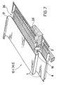
- a flat collector module 10.1 which consists of a flat, rectangular sheet metal panel 1, a register-like arrangement 30 of mutually parallel capillary tube 3.1 .... 3.n and a thermally insulating insulating core 4 from Polyurethane hard foam exists.
- the insulating core 4 has a thickness of 25 mm.
- the material of the pre-weathered and thus darker sheet metal panel 1 is a titanium-zinc alloy, here: a product of the Applicant, RHEINZINK GmbH & Co. KG in Datteln.
- the surface treatment achieves a higher degree of absorption because there is less reflection.
- the sheet metal panel 1 has two angled, arcuate edges 16, 17, which for connection to adjacent Metal sheet panels are used to produce a stepped roof 40 as shown in FIG.
- the existing plastic capillary tube 3.1 .... 3.n each have an outer diameter of about 2.5 to 3.5 mm.
- the capillary tubes 3.1 .... 3.n run at a uniform distance A of about 8 to 15 mm from each other.
- approximately 30 parallel arranged capillary tube sections can be accommodated in the individual flat collector module 10.1 of width 400 mm.
- the sheet metal panel 1 is connected via an elastic adhesive layer 2 with the insulating core 4, which has a thickness which does not exceed the outer diameter of the capillary tube.
- a liquid adhesive is sprayed onto a horizontal surface 5 of the insulating core 4 and shortly thereafter the entire assembly 30 of the capillary tube 3.1 .... 3.n placed with the sheet metal panel 1 and pressed until the capillary tubes are embedded ,
- the adhesive used in the present case is a cold-curing one-component polyurethane-based adhesive, a product of Sika GmbH, Stuttgart. After curing, the adhesive layer 2 remains permanently elastic.
- a novel flat collector module which has a positive but elastic connection of the insulating core 4 with the sheet metal panel 1, which compound is formed by the adhesive layer 2, which surrounds the standing in contact with the sheet metal panel capillary tube ,
- the existing polypropylene polypropylene capillary tube 3.1 .... 3.n are also elastic and thus can yield in the state of stress.
- the relatively thin insulation core 4 made of rigid polyurethane foam gives the composite sufficient stability so that it can be laid directly on the roof battens 26 of the roof substructure (see FIG.
- grooves 14 for accommodating capillary tubes 3.1... 3.n are incorporated on the surface 5 of the insulating core 4.
- FIGS. 2 and 4 show a metal cassette 20 surrounding the insulating core 4 (here: aluminum sheet), which stiffens the entire composite without having to accept loss of elasticity of the adhesive bond.
- the metal cassette 20 has two opposite, outwardly angled and mutually mirror-symmetrically arranged edges 21 which rest on the bottom 11.2 of the sheet metal panel. Between the sheet metal panel 1 and the angled edges 21 of the metal cassette 20, elastic bodies 22 are each arranged in the form of a soft foam strip, which has the tasks to suppress the heat conduction and to allow the relative displacements of the sheet metal panel and the metal cassette.
- the metal cassette 20 is glued in places with the insulating core 4.
- Fig. 2 numerous depressions 6 can be seen, which are incorporated on the surface 5 of the insulating core 4 by the contact pressure of a not shown, optionally heated to a temperature of about 200 ° C bristle roller. In the recesses 6 of the liquid adhesive flows and hardens there.
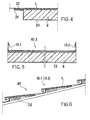
- FIG. 5 another flat collector module (reference numeral 10.3) is shown, which differs from the flat collector module shown in FIG. 1 in that the sheet metal panel instead of the arcuate edges two angularly bent edges 13.1, 13.2 for connection the sheet metal panels with each other in folding technique. Furthermore, insulating core 4 is underlaid on its side facing away from the sheet metal panel 1 side with a plate-shaped reinforcing element 23. The stiffening element 23 is also made of aluminum sheet and is glued to the insulating core 4.
Landscapes
- Engineering & Computer Science (AREA)
- Chemical & Material Sciences (AREA)
- Combustion & Propulsion (AREA)
- Mechanical Engineering (AREA)
- Physics & Mathematics (AREA)
- Sustainable Development (AREA)
- Sustainable Energy (AREA)
- Thermal Sciences (AREA)
- General Engineering & Computer Science (AREA)
- Life Sciences & Earth Sciences (AREA)
- Dispersion Chemistry (AREA)
- Laminated Bodies (AREA)
- Roof Covering Using Slabs Or Stiff Sheets (AREA)
- Vaporization, Distillation, Condensation, Sublimation, And Cold Traps (AREA)
- Catalysts (AREA)
- Building Environments (AREA)
Description
- Die Erfindung betrifft einen selbsttragenden, heliothermischen Flachkollektor-Modul, der umfasst:
- ein Metallblech-Paneel,
- eine registerartige Anordnung von untereinander in Abstand liegenden Kapillar-Röhrchen für den Durchlauf eines flüssigen Mediums, die auf der der zu bestrahlenden Seite abgewandten Rückseite des Metallblech-Paneels liegt,
- und einen thermoisolierenden Dämmstoffkern, der ebenfalls rückseitig angeordnet ist.
- Ein Flachkollektor-Modul dieser Art ist aus der DE-PS 100 43 295 der Anmelderin bekannt. Diese Schrift sieht grundsätzlich vor, die Kapillar-Röhrchen durch Aufspritzen von flüssigen Metallpartikeln mit dem Blechpaneel zu verbinden. Der DE-PS 100 43 295 ist auch eine Klebeverbindung des mit den Kapillar-Röhrchen bestückten Blechpaneels mit einem Schaumstoffkern zu entnehmen, allerdings sind die Einzelheiten der Klebeverbindung nicht angegeben.
- Eine solche Klebeverbindung stellt bei den heliothermischen Flachkollektor-Modulen ein technisches Problem dar, da die Fügeteile unterschiedliche Elastizitätsmodule aufweisen und dadurch mehrachsige Spannungzustände entstehen können. Insbesondere kann das der Sonneneinstrahlung ausgesetzte Blechpaneel stark erwärmt und deformiert werden. Infolgedessen kann die Klebeverbindung wenigstens stellenweise zerstört und der Kontakt zwischen den Kapillar-Röhrchen und dem Blechpaneel unterbrochen werden.
- Aufgabe der Erfindung ist, die vorgenannten Nachteile zu vermeiden und einen selbsttragenden, heliothermischen Flachkollektor-Modul der eingangs genannten Art anzugeben, bei dem der Dämmstoffkern mit dem Blechpaneel, insbesondere aus einer Titan-Zink-Legierung, spannungsfrei über einen großen Temperaturbereich verbunden werden kann.
- Diese Aufgabe ist durch einen selbsttragenden, heliothermischen Flachkollektor-Modul der eingangs genannten dadurch gelöst, dass
- die Kapillar-Röhrchen der registerartigen Anordnung kontaktierend auf eine Oberfläche des thermoisolierenden Dämmstoffkerns gelegt sind,
- und dass der thermoisolierende Dämmstoffkern über eine elastische Klebeschicht mit dem Metallblech-Paneel verbunden ist, wobei Kapillar-Röhrchen wenigstens teilweise innerhalb der Klebeschicht zwischen dem Metallblech-Paneel und dem Dämmstoffkern eingebettet sind.
- Die Kapillar-Röhrchen können jeweils in eine in dem thermoisolierenden Dämmstoffkern eingearbeitete Nut platziert sein, wobei die Kapillar-Röhrchen im wesentlichen bündig mit dem Dämmstoffkern liegen oder um einen Betrag über den Dämmstoffkern hinausragen, welcher Betrag im wesentlichen einem Dickenmaß der flüssigen Klebeschicht vor dem Aushärten entspricht.
- Alternativ können die Kapillar-Röhrchen der registerartigen Anordnung direkt auf eine plane Oberfläche des thermoisolierenden Dämmstoffkerns gelegt sein.
- In beiden Fällen kann wenigstens der thermoisolierende Dämmstoffkern über die elastische Klebeschicht mit dem Metallblech-Paneel verbunden sein. Dies bedeutet, dass die dem Metallblech-Paneel zugewandten Scheitelbereiche der Kapillar-Röhrchen direkt mit dem Metallblech-Paneel in Kontakt stehen können, ohne dass der Klebstoff in die Scheitelbereiche gelangt. Die Kapillar-Röhrchen können auch gänzlich vom Klebstoff umgeben sein, insbesondere dann, wenn sich der Klebstoff durch wärmeleitende Eigenschaften auszeichnet. Diese Eigenschaften können dem Klebstoff beispielsweise durch Beimischung vom Metallpulver verliehen werden.
- Weiterhin ist denkbar, dem Klebstoff Fasern von kurzer Stapellänge homogen beizumischen, damit sich eine erhöhte Tragfähigkeit bzw. Stabilität der Klebeschicht ergibt. Diese Faserabschnitte können beispielsweise eine Stapellänge zwischen 0,5 mm und 3 mm aufweisen. Zu diesem Zweck eignen sich vorzugsweise Glasfasern.
- Die plane oder mit den Nuten versehene Oberfläche des Schaumstoffkerns kann zahlreiche Vertiefungen zur Aufnahme von noch flüssigen Klebesubstanz aufweisen, die vorzugsweise bis zur Nuttiefe reichen oder diese geringfügig überschreiten. Diese Maßnahme kann der Stabilität des Verbundes beitragen. Die Vertiefungen können beispielsweise durch Anpreßkraft einer Borstenwalze, eines gegebenenfalls erhitzten Stempels oder dgl. hergestellt werden.
- Der thermoisolierende Dämmstoffkern kann aus Schaumstoff, insbesondere aus Polystyrol- oder Polyurethan-Hartschaum, oder aus faserigem Material, wie Mineralwolle, bestehen.
- Dadurch, dass die klebtechnischen Eigenschaften der Kunststoffe, darin Hartschäume, gegenüber denen der Metalle wesentlich eingeschränkt sind, gelangen praktisch ausschließlich Reaktionsklebstoffe nach dem Prinzip der Adhäsionsklebung zur Anwendung. Eine Diffusionsklebung ist wegen der Undurchlässigkeit des Metallblech-Paneels nicht geeignet.
- So kann die Klebeschicht beispielsweise durch einen organischen, chemisch abbindenden 1-Komponenten-Klebstoff auf Methacrylat-Basis gebildet sein. Die Klebeschicht kann auch durch andere Klebstoffe gebildet sein, die sich durch den guten Haft an Metallen und Kunststoffen auszeichnen. Hierzu können insbesondere Reaktionsklebstoffe auf Basis von Styrol-Copolymerisaten oder elastomere PUR-Harze eingesetzt werden. Wichtig ist, dass die Klebeschicht nach dem Aushärten dauerhaft elastisch bleibt und infolge der späteren Sonneneinstrahlung nicht zu fließen beginnt. Das Verformungsvermögen der entstandenen, bereits ausgehärteten Klebeschicht erlaubt es, die Spannungszustände auszugleichen.
- Das Metallblech-Paneel kann einstückig mit zwei abgewinkelten, bogenförmigen Randprofilen ausgeführt sein, mit denen sich eine treppenförmige Konfiguration der Dachhaut herstellen lässt.
- Das Metallblech-Paneel kann ebenso einstückig mit zwei gegenüberliegenden, winkelig abgebogenen Kanten zur Verbindung der Metallblech-Paneele miteinander in Falztechnik ausgeführt sein.
- Der Flachkollektor-Modul gemäß Erfindung kann mit wenigstens einem planken- oder plattenförmigen Versteifungselement versehen sein, das an einer dem Metallblech-Paneel abgewandten Seite des Dämmstoffkerns angeordnet ist.
- Bei einer weiteren Ausführungsform kann am Dämmstoffkern eine Kunststoff- oder Metallkassette aufgesetzt sein, welche zwei gegenüberliegende, nach außen abgewinkelte Ränder aufweist, mit denen sich die Kunststoff- oder Metallkassette an der Unterseite des Metallblech-Paneels abstützt. Zwischen dem Metallblech-Paneel und dem abgewinkelten Rand der Metallkassette kann ein elastischer Körper, wie Schaumstoff- oder Gummistreifen, bzw. ein elastisches Klebeband liegen. Das Material des elastischen Körpers soll jedoch älterungs- und witterungsbeständig sein.
- Die Kapillar-Röhrchen bestehen aus Metall, vorzugsweise aus Kupfer oder Edelstahl. Es ist aber nicht ausgeschlossen, anstelle der metallenen peripher metallbeschichtete Kunststoff-Rohre oder unbeschichtete Kunststoff-Rohre zu verwenden.
- Wird der Dämmstoffkern entsprechend stabil und die hergestellte Klebeverbindung zwischen dem Dämmstoffkern und dem Metallblech-Paneel ausreichend elastisch, so kann auf die Metallkassette bzw. auf das untere Versteifungselement verzichtet werden.
- Von großem Vorteil ist, dass der Wärmekontakt zwischen dem Rohrsystem und dem Metallblech-Paneel ununterbrochen ist, da die Kapillar-Röhrchen in die Klebeschicht eingebettet und durch das Metallblech-Paneel und den Dämmstoffkern zusammengedrückt sind. Dadurch kann auch die Kondenswasserbildung und elektrochemische Korrosion vermieden werden.
- Selbstverständlich können die Flachkollektor-Module zum Kühlen des jeweiligen Raums genutzt werden, da die Wärme über den Kollektor abgegeben werden kann. Außerdem besteht die Möglichkeit, die gewonnene Wärmeenergie zum Schmelzen des Schnees im Winter auszunutzen. Es kann beispielsweise eine kombinierte, automatisch gesteuerte Technik gewählt werden, bei der eine sogenannte Direktheizung durch Flachkollektor-Module unterstützt werden kann.
- Es wird ausdrücklich darauf hingewiesen, dass der Flachkollektor-Modul gemäß Erfindung ein Niedrigtemperatur-Flachkollektor ist, bei dem kein "Treibhauseffekt" auftritt, d.h. auf der zu bestrahlenden Seite des Metallblech-Paneels keine zusätzliche transparente Abdeckungen vorhanden sind, die normalerweise einen abgedichteten, aufzuheizenden Raum bilden. Das Metallblech-Paneel ist also direkt den Sonnenstrahlen ausgesetzt.
- Ausführungsbeispiele der Erfindung sind anhand der Zeichnung näher dargestellt. Die Figuren zeigen:
- Figuren 1 und 2
- einen Abschnitt eines Flachkollektor-Moduls in zwei Ausführungsformen, in einem schematischen Schnitt;
- Fig. 3
- ein vergrößertes Detail des Schnitts gemäß der Fig. 2;
- Fig. 4
- Anordnung eines elastischen Körpers zwischen dem Metallblechpaneel und einer Metallkassette;
- Fig. 5
- einen zur Verbindung in Falztechnik geeigneten Flachkollektor-Modul, in einem schematischen Schnitt;
- Fig. 6
- schematisch einen Abschnitt eines Treppendaches mit eingebauten Flachkollektor-Modulen, im Schnitt; und
- Fig. 7
- den Flachkollektor-Modul gemäß Fig. 1 in einer perspektivischen, schematischen Ansicht.
- In den Figuren 1 und 7 ist ein Flachkollektor-Modul 10.1 dargestellt, der aus einem flachen, rechteckigen Metallblech-Paneel 1, einer registerartigen Anordnung 30 von zueinander parallel verlaufenden Kapillar-Röhrchen 3.1....3.n und einem thermoisolierenden Dämmstoffkern 4 aus Polyurethan-Hartschaum besteht. Der Dämmstoffkern 4 hat eine Dicke 25 mm. Das Material des vorbewitterten und dadurch dunkleren Metallblech-Paneels 1 ist eine Titan-Zink-Legierung, hier: ein Produkt der Anmelderin, RHEINZINK GmbH & Co. KG in Datteln. Durch die Oberflächenbehandlung wird ein höher Absorptionsgrad erzielt, da weniger Reflexion stattfindet.
- Das Metallblech-Paneel 1 weist folgende Ausmaße auf:
- Länge 3000 mm,
- Breite 400 mm,
- Dicke 0,8 mm.
- Ferner weist das Metallblech-Paneel 1 zwei abgewinkelte, bogenförmige Ränder 16, 17 auf, die zur Verbindung mit benachbarten Metallblech-Paneelen dienen, um ein Treppendach 40 gemäß der Fig. 6 herstellen zu können.
- Die aus Kunststoff bestehenden Kapillar-Röhrchen 3.1....3.n weisen jeweils einen Außendurchmesser von etwa 2,5 bis 3,5 mm auf. Die Kapillar-Röhrchen 3.1....3.n verlaufen in einem einheitlichen Abstand A von etwa 8 bis 15 mm voneinander. So können im einzelnen Flachkollektor-Modul 10.1 von der Breite 400 mm etwa 30 parallel angeordnete Kapillar-Rohrabschnitte untergebracht sein.
- Das Metallblech-Paneel 1 ist über eine elastische Klebeschicht 2 mit dem Dämmstoffkern 4 verbunden, welche eine Dicke aufweist, die den Außendurchmesser des Kapillar-Röhrchens nicht überschreitet. Ein flüssiger Klebstoff wird auf eine waagerecht liegende Oberfläche 5 des Dämmstoffkerns 4 aufgesprüht und kurz danach die gesamte Anordnung 30 der Kapillar-Röhrchen 3.1....3.n mit dem Metallblech-Paneel 1 gelegt und gedrückt, bis die Kapillar-Röhrchen eingebettet sind.
- Als Klebstoff wird im vorliegenden Fall ein kalthärtender Ein-Komponenten-Klebstoff auf Polyurethan-Basis, ein Produkt der Firma Sika GmbH, Stuttgart, verwendet. Nach dem Aushärten verbleibt die Klebeschicht 2 dauerhaft elastisch.
- Insgesamt ist ein neuartiger Flachkollektor-Modul geschaffen, der eine formschlüssige, jedoch elastische Verbindung des Dämmstoffkerns 4 mit dem Metallblech-Paneel 1 aufweist, welche Verbindung durch die Klebeschicht 2 gebildet ist, die die in Kontakt mit dem Metallblech-Paneel stehenden Kapillar-Röhrchen umgibt. Die aus Polypropylen bestehenden Kapillar-Röhrchen 3.1....3.n sind ebenfalls elastisch und dadurch im Spannungszustand nachgeben können.
- Der relativ dünne Dämmstoffkern 4 aus Polyurethan-Hartschaum verleiht dem Verbund eine ausreichende Stabilität, so dass dieser direkt auf den Dachlatten 26 des Dach-Unterbaus (vgl. Fig. 6) verlegt werden kann.
- Durch die verwendete Klebeverbindung mit eingebetteten Kapillar-Röhrchen und die Auswahl von Dämmstoffen und deren Dicken ist eine vorteilhafte, niedrige Gesamtdicke des Flachkollektor-Moduls erzielt worden. Diese beträgt im vorliegenden Fall 25 mm.
- Bei einer anderen, in den Figuren 2 bis 4 gezeigten Ausführungsform (Bezugszeichen 10.2) sind an der Oberfläche 5 des Dämmstoffkerns 4 Nuten 14 zur Aufnahme von Kapillar-Röhrchen 3.1.....3.n eingearbeitet. Die Kapillar-Röhrchen ragen über den Dämmstoffkern 4 um einen kleinen Betrag H = 1,5 mm hinaus, welcher Betrag einem Dickenmaß D der noch flüssigen Klebeschicht 2 vor dem Aushärten entspricht.
- Weiterhin ist den Figuren 2 und 4 eine den Dämmstoffkern 4 umgebende Metallkassette 20 (hier: Aluminiumblech) zu entnehmen, die den gesamten Verbund versteift, ohne Einbuße an Elastizität der Klebeverbindung hinnehmen zu müssen. Die Metallkassette 20 weist zwei gegenüberliegende, nach außen abgewinkelte und zueinander spiegelsymmetrisch angeordnete Ränder 21 auf, die an der Unterseite 11.2 des Metallblech-Paneels aufliegen. Zwischen dem Metallblech-Paneel 1 und den abgewinkelten Rändern 21 der Metallkassette 20 sind elastische Körper 22 jeweils in Form eines weichen Schaumstoffstreifens angeordnet, der die Aufgaben hat, die Wärmeleitung zu unterbinden und die relativen Verschiebungen des Metallblech-Paneels und der Metallkassette zu ermöglichen.
- Die Metallkassette 20 ist stellenweise mit dem Dämmstoffkern 4 verklebt.
- Ferner sind in der Fig. 2 zahlreiche Vertiefungen 6 zu sehen, welche an der Oberfläche 5 des Dämmstoffkerns 4 durch Anpreßkraft einer nicht dargestellten, gegebenenfalls bis zur Temperatur etwa 200°C erhitzten Borstenwalze eingearbeitet sind. In die Vertiefungen 6 fließt der flüssige Klebstoff ein und erhärtet dort.
- In Fig. 5 ist ein weiterer Flachkollektor-Modul (Bezugszeichen 10.3) dargestellt, der sich von dem in der Fig. 1 gezeigten Flachkollektor-Modul dadurch unterscheidet, dass das Metallblech-Paneel anstelle der bogenförmigen Ränder zwei winkelig abgebogene Kanten 13.1, 13.2 zur Verbindung der Metallblech-Paneele miteinander in Falztechnik aufweist. Weiterhin ist Dämmstoffkern 4 an seiner dem Metallblech-Paneel 1 abgewandten Seite mit einem plattenförmigen Versteifungselement 23 unterlegt. Das Versteifungselement 23 besteht ebenfalls aus Aluminiumblech und ist mit dem Dämmstoffkern 4 verklebt.
-
- 1
- Metallblech-Paneel
- 2
- Klebeschicht
- 3.1...3.n
- Kapillar-Röhrchen
- 4
- Dämmstoffkern
- 5
- Oberfläche
- 6
- Vertiefung
- 10.1; 10.2; 10.3
- Flachkollektor-Modul
- 13.1, 13.2
- Kante
- 14
- Nut
- 16
- Rand
- 17
- Rand
- 20
- Metallkassette
- 21
- Rand
- 22
- Körper
- 23
- Versteifungselement
- 26
- Dachlatte
- 30
- Anordnung
- 40
- Treppendach
- A
- Abstand
- D
- Dickenmaß
- H
- Betrag
- TN
- Nuttiefe
Claims (22)
- Selbsttragender, heliothermischer Flachkollektor-Modul (10.1; 10.3), umfassend:- ein Metallblech-Paneel (1),- eine registerartige Anordnung (30) von untereinander in Abstand liegenden Kapillar-Röhrchen (3.1.....3.n) für den Durchlauf eines flüssigen Mediums, die auf der der zu bestrahlenden Seite (11.1) abgewandten Rückseite (11.2) des Metallblech-Paneels (1) liegt,- und einen thermoisolierenden Dämmstoffkern (4), der ebenfalls rückseitig angeordnet ist,dadurch gekennzeichnet, dass- die Kapillar-Röhrchen (3.1.....3.n) der registerartigen Anordnung (30) kontaktierend auf eine Oberfläche (5) des thermoisolierenden Dämmstoffkerns (4) gelegt sind,- und dass der thermoisolierende Dämmstoffkern (4) über eine elastische Klebeschicht (2) mit dem Metallblech-Paneel (1) verbunden ist, wobei die Kapillar-Röhrchen (3.1.....3.n) wenigstens teilweise innerhalb der Klebeschicht zwischen dem Metallblech-Paneel (1) und dem Dämmstoffkern (4) eingebettet sind.
- Flachkollektor-Modul (10.2) nach Anspruch 1, dadurch gekennzeichnet, dass die Kapillar-Röhrchen (3.1.....3.n) der registerartigen Anordnung (30) jeweils in eine in dem thermoisolierenden Dämmstoffkern (4) eingearbeitete Nut (14) platziert sind, wobei die Kapillar-Röhrchen (3.1.....3.n) mit dem Dämmstoffkern (4) im wesentlichen bündig liegen oder um einen Betrag (H) über den Dämmstoffkern (4) hinausragen, welcher Betrag im wesentlichen einem Dickenmaß (D) einer flüssigen Klebeschicht (2) vor dem Aushärten entspricht.
- Flachkollektor-Modul (10.2) nach Anspruch 1, dadurch gekennzeichnet, dass die Oberfläche des Dämmstoffkerns plan ist und dass die Kapillar-Röhrchen (3.1.....3.n) direkt auf die plane Oberfläche gelegt sind.
- Flachkollektor-Modul nach Anspruch 1 bis 3, dadurch gekennzeichnet, dass der thermoisolierende Dämmstoffkern (4) aus Schaumstoff besteht.
- Flachkollektor-Modul nach Anspruch 4 dadurch gekennzeichnet, dass der Schaumstoff aus geschäumtem Polystyrol oder Polyurethan besteht.
- Flachkollektor-Modul nach Anspruch 1 bis 3, dadurch gekennzeichnet, dass der thermoisolierende Dämmstoffkern (4) im wesentlichen aus Fasern besteht.
- Flachkollektor-Modul nach einem der Ansprüche 1 bis 5, dadurch gekennzeichnet, dass das Material der Klebeschicht (2) relativ zum Material des Dämmstoffkerns einen höheren Wärmeleitkoeffizienten hat.
- Flachkollektor-Modul nach einem der Ansprüche 1 bis 5, dadurch gekennzeichnet, dass die Klebeschicht (2) aus einem Klebstoff auf Methacrylat-Basis gebildet ist.
- Flachkollektor-Modul nach Anspruch 2, dadurch gekennzeichnet, dass die Nuten (14) in ihrem Querschnitt drei- oder rechteckig, oval bzw. teilkreis- oder Ω-förmig sind.
- Flachkollektor-Modul nach einem der vorhergehenden Ansprüche, dadurch gekennzeichnet, dass die KapillarRöhren (3.1.....3.n) aus Metall, aus peripher metallbeschichtetem Kunststoff oder aus unbeschichtetem Kunststoff bestehen.
- Flachkollektor-Modul nach einem der vorhergehenden Ansprüche, dadurch gekennzeichnet, dass die plane oder mit den Nuten (14) versehene Oberfläche (5) des Dämmstoffkerns (4) zahlreiche Vertiefungen (6) zur Aufnahme von Klebstoff aufweist.
- Flachkollektor-Modul nach Ansprüche 2 und 11, dadurch gekennzeichnet, dass die Vertiefungen (6) im wesentlichen bis zur Nuttiefe (TN) reichen oder diese geringfügig überschreiten.
- Flachkollektor-Modul nach Anspruch 11 und 12, dadurch gekennzeichnet, dass die Vertiefungen (6) durch Anpresskraft einer Borstenwalze oder dgl. entstanden sind.
- Flachkollektor-Modul nach einem der vorhergehenden Ansprüche, dadurch gekennzeichnet, dass das Metallblech-Paneel (1) einstückig mit zwei abgewinkelten, bogenförmigen Randprofilen (16; 17) ausgeführt ist.
- Flachkollektor-Modul nach einem der vorhergehenden Ansprüche, dadurch gekennzeichnet, dass das Metallblech-Paneel (1) einstückig mit zwei gegenüberliegenden, winkelig abgebogenen Kanten (13.1, 13.2) zur Verbindung der Metallblech-Paneele miteinander in Falztechnik ausgeführt ist.
- Flachkollektor-Modul nach einem der vorhergehenden Ansprüche, dadurch gekennzeichnet, dass der Dämmstoffkern (4) an seiner dem Metallblech-Paneel (1) abgewandten Seite mit einem plattenförmigen Versteifungselement (23) unterlegt ist.
- Flachkollektor-Modul nach einem der vorhergehenden Ansprüche, dadurch gekennzeichnet, dass der Dämmstoffkern (4) teilweise von einer Kunststoff- oder Metallkassette (20) umgeben ist.
- Flachkollektor-Modul nach Anspruch 17, dadurch gekennzeichnet, dass die Metallkassette (20) zwei gegenüberliegende, nach außen abgewinkelte Ränder (21) aufweist, wobei zwischen dem Metallblech-Paneel (1) und dem abgewinkelten Rand (21) der Metallkassette (20) ein elastischer Körper (22) angeordnet ist.
- Flachkollektor-Modul nach Anspruch 18, dadurch gekennzeichnet, dass der elastische Körper (22) ein Schaumstoffstreifen oder Klebeband ist.
- Flachkollektor-Modul nach einem der vorhergehenden Ansprüche, dadurch gekennzeichnet, dass die Metallblech-Paneele (1) aus einer Titan-Zink-Legierung bestehen.
- Flachkollektor-Modul nach einem der vorhergehenden Ansprüche, dadurch gekennzeichnet, dass dieser eine Gesamtdicke - inklusive Dämmstoffkern - zwischen 10 mm und 50 mm, vorzugsweise zwischen 25 mm und 35 mm aufweist.
- Flachkollektor-Modul nach Anspruch 1 und nach weiteren Ansprüchen 2 bis 21, eingebaut in ein Treppendach (40), dessen Dachhaut aus miteinander verbundenen Metallblech-Paneelen (1) besteht.
Applications Claiming Priority (3)
| Application Number | Priority Date | Filing Date | Title |
|---|---|---|---|
| DE20216297U DE20216297U1 (de) | 2002-10-23 | 2002-10-23 | Heliothermischer Flachkollektor-Modul in Sandwichbauweise |
| DE20216297U | 2002-10-23 | ||
| PCT/EP2003/011573 WO2004038306A1 (de) | 2002-10-23 | 2003-10-18 | Heliothermischer flachkollektor-modul in sandwichbauweise |
Publications (2)
| Publication Number | Publication Date |
|---|---|
| EP1554527A1 EP1554527A1 (de) | 2005-07-20 |
| EP1554527B1 true EP1554527B1 (de) | 2006-11-29 |
Family
ID=7976225
Family Applications (1)
| Application Number | Title | Priority Date | Filing Date |
|---|---|---|---|
| EP03773652A Expired - Lifetime EP1554527B1 (de) | 2002-10-23 | 2003-10-18 | Heliothermischer flachkollektor-modul in sandwichbauweise |
Country Status (10)
| Country | Link |
|---|---|
| US (1) | US7610911B2 (de) |
| EP (1) | EP1554527B1 (de) |
| JP (1) | JP4445391B2 (de) |
| CN (1) | CN100425926C (de) |
| AT (1) | ATE347079T1 (de) |
| AU (1) | AU2003282037B8 (de) |
| DE (2) | DE20216297U1 (de) |
| DK (1) | DK1554527T3 (de) |
| ES (1) | ES2277125T3 (de) |
| WO (1) | WO2004038306A1 (de) |
Families Citing this family (35)
| Publication number | Priority date | Publication date | Assignee | Title |
|---|---|---|---|---|
| DE20216297U1 (de) * | 2002-10-23 | 2003-01-09 | Rheinzink GmbH & Co. KG, 45711 Datteln | Heliothermischer Flachkollektor-Modul in Sandwichbauweise |
| DE102005015059A1 (de) * | 2005-03-31 | 2006-10-05 | Aros Hydraulik Gmbh | Verriegelbarer Arbeitszylinder |
| PL209166B1 (pl) * | 2005-04-04 | 2011-07-29 | Dariusz Dżegan | Płyta budowlana |
| US20070056579A1 (en) * | 2005-09-09 | 2007-03-15 | Straka Christopher W | Energy Channeling Sun Shade System and Apparatus |
| US20080313963A1 (en) * | 2005-10-07 | 2008-12-25 | Fiberline A/S | Window Element, a Profiled Pultruded Panel, a System of a Profiled Pultruded Panel and One or More Fixation Elements, a Covering of a Buidling or a House, a Building or a House, a Method of Providing an Outer Weather Resistant Covering, and a Building Element |
| DE102006027629B4 (de) * | 2006-06-13 | 2013-10-17 | Willi Bihler | Solarelement mit Temperiereinrichtung, Verfahren zur Herstellung, Bausatz, Verwendung für eine Solarenergieanlage sowie Solarenergieanlage |
| US9663955B2 (en) * | 2006-06-19 | 2017-05-30 | Daniel Efrain Arguelles | Pan tile roofing system |
| ITBZ20060033A1 (it) * | 2006-07-28 | 2008-01-29 | Alberto Volcan | Pannello solare, in particolare tegola. |
| FR2912442A1 (fr) * | 2007-01-08 | 2008-08-15 | Cyril Alain Lepretre | Procede de capteur thermique solaire integre aux toitures et terrasses |
| ES2710354T3 (es) * | 2007-04-18 | 2019-04-24 | Cupa Innovacion Slu | Un panel de transmisión de energía para la incorporación invisible en un edificio y un casete que comprende tal panel |
| ES2310124B1 (es) * | 2007-05-17 | 2009-11-11 | Antonio Molina Alcolea | Elemento energetico estructural. |
| RU2329437C1 (ru) * | 2007-06-04 | 2008-07-20 | Борис Иванович Казанджан | Солнечный коллектор (варианты) и способ изготовления оболочки солнечного коллектора |
| DE102009040653A1 (de) | 2008-09-09 | 2010-06-17 | Sola-Term Gmbh | Solar-Flachkollektor |
| ES2334876B1 (es) * | 2008-09-15 | 2010-12-28 | Cupa Innovacion, S.L.U. | Panel de cubierta captador de energia solar. |
| NL1036855C2 (nl) * | 2009-04-15 | 2010-10-18 | Cons Groep B V | Warmtecollector en warmte collecterende dakconstructie. |
| NL2003336C2 (nl) * | 2009-04-15 | 2011-08-11 | Cons Groep B V | Warmtecollector en warmte collecterende dakconstructie. |
| DE102010036383A1 (de) * | 2009-10-07 | 2011-05-26 | Ludger Hambrock | Solarbauelement für Solarthermieanlagen, Solarthermieanlage, Verfahren zum Betreiben einer Solarthermieanlage und Teile eines Solarbauelements für Solarthermieanlage |
| US9027300B2 (en) | 2010-01-20 | 2015-05-12 | Propst Family Limited Partnership | Building panel system |
| US20140150362A1 (en) | 2010-01-20 | 2014-06-05 | Propst Family Limited Partnership | Building panels and method of forming building panels |
| US8695299B2 (en) | 2010-01-20 | 2014-04-15 | Propst Family Limited Partnership | Building panel system |
| US9032679B2 (en) * | 2010-01-20 | 2015-05-19 | Propst Family Limited Partnership | Roof panel and method of forming a roof |
| EP2362157A1 (de) * | 2010-02-18 | 2011-08-31 | go!nnovate AG | Solarkollektor |
| ES2400765B1 (es) | 2010-06-30 | 2014-02-14 | Cupa Innovacion, S.L.U. | Panel de cubierta captador de energia solar |
| WO2012059123A1 (en) * | 2010-11-02 | 2012-05-10 | Luvata Espoo Oy | A channel arrangement for a solar absorber, a solar absorber, use of a channel arrangement |
| CN102628617B (zh) * | 2012-05-08 | 2014-06-25 | 沈阳建筑大学 | 一种低成本双效太阳能空气集热器 |
| CN102954602B (zh) * | 2012-12-05 | 2015-11-11 | 江苏格隆科技有限公司 | 液体介质型建筑一体化屋面整体集热器 |
| EP2789761A1 (de) * | 2013-04-08 | 2014-10-15 | European Investment Group B.V. | Gebäudeschutz- und verkleidungselement |
| AU2014315407B2 (en) | 2013-09-05 | 2018-12-13 | Alion Energy, Inc. | Systems, vehicles, and methods for maintaining rail-based arrays of photovoltaic modules |
| US9453660B2 (en) | 2013-09-11 | 2016-09-27 | Alion Energy, Inc. | Vehicles and methods for magnetically managing legs of rail-based photovoltaic modules during installation |
| WO2017044566A1 (en) | 2015-09-11 | 2017-03-16 | Alion Energy, Inc. | Wind screens for photovoltaic arrays and methods thereof |
| US20170331414A1 (en) * | 2016-05-16 | 2017-11-16 | Alion Energy, Inc. | Feet of solar collector support structures, joints between feet of solar collector support structures and concrete, and methods of forming the same |
| US10969144B2 (en) * | 2017-08-16 | 2021-04-06 | Art Brisebois | Thin multi-channel heat exchanger |
| JP7211618B2 (ja) * | 2018-11-01 | 2023-01-24 | 俊明 前田 | 遮熱兼熱交換装置 |
| US11035130B1 (en) | 2019-02-01 | 2021-06-15 | Daniel Efrain Arguelles | Synthetic mechanically attached roof underlayment system |
| FR3102195B1 (fr) * | 2019-10-18 | 2022-06-10 | Air Booster | dispositif modulaire de toiture aérothermique |
Family Cites Families (24)
| Publication number | Priority date | Publication date | Assignee | Title |
|---|---|---|---|---|
| US4000850A (en) * | 1975-05-14 | 1977-01-04 | Diggs Richard E | Solar heated and cooled modular building |
| US4074406A (en) * | 1976-06-25 | 1978-02-21 | Boyd John B | Method for manufacturing solar energy collectors |
| SE7613694L (sv) * | 1976-12-06 | 1978-06-07 | Platell Ove Bertil | Anordning for overforing av verme. |
| US4144874A (en) * | 1977-06-10 | 1979-03-20 | Sunhouse, Incorporated | Solar panel |
| DE2733899A1 (de) * | 1977-07-27 | 1979-02-01 | Pan Therm Gmbh Ges Fuer Planun | Bausatz fuer klimadaecher oder klimafassaden |
| US4191169A (en) * | 1978-02-06 | 1980-03-04 | Solar Heat Corporation | Solar energy panel |
| FR2465966A1 (fr) * | 1978-08-04 | 1981-03-27 | Monopanel Sa | Capteur solaire formant panneau auto-porteur pour batiment |
| AT365697B (de) * | 1978-09-13 | 1982-02-10 | Gewerbe Handel Ind Management | Mehrzweck-bauelement |
| AU534683B2 (en) * | 1979-10-23 | 1984-02-09 | Ahearn Main & Stott Pty. Ltd. | Strip for forming a solar collector |
| ZA824646B (en) * | 1981-07-09 | 1983-04-27 | Ti Ltd | Heat exchangers |
| US4606327A (en) * | 1982-11-09 | 1986-08-19 | Bloor Trevor J | Solar water heating apparatus |
| GB8527874D0 (en) | 1985-11-12 | 1985-12-18 | Walker R D | Heat exchange elements |
| US4911353A (en) * | 1986-03-31 | 1990-03-27 | David Deakin | Solar collector having absorber plate formed by spraying molten metal |
| US5167218A (en) * | 1986-03-31 | 1992-12-01 | David Deakin | Solar collector having absorber plate formed by spraying molten metal |
| JP2613719B2 (ja) * | 1992-09-01 | 1997-05-28 | キヤノン株式会社 | 太陽電池モジュールの製造方法 |
| DE4423137C2 (de) * | 1994-07-01 | 1998-05-20 | Loba Bautenschutz Gmbh & Co Kg | Gebäudeaußenwand |
| AU1153499A (en) * | 1997-10-15 | 1999-05-03 | Rohm Gmbh | Solar module with a functionally integrated rear side |
| CN2317445Y (zh) * | 1998-03-20 | 1999-05-05 | 中国科学院广州能源研究所 | 一种高效的平板太阳能集热器 |
| FR2777984B1 (fr) | 1998-04-22 | 2000-07-28 | Toutenkamion | Panneau solaire et dispositif de collecte d'energie solaire |
| DE19907518C1 (de) | 1999-02-22 | 2000-11-30 | Saskia Solar Und Energietechni | Sonnenkollektor |
| DE10043295C1 (de) * | 2000-09-02 | 2002-04-25 | Rheinzink Gmbh | Heliothermischer Flachkollektor-Modul |
| DE20021415U1 (de) | 2000-12-19 | 2001-05-03 | Rockendorf, Gunter, Dipl.-Ing., 30826 Garbsen | Vorrichtung zur Abfuhr von Wärme, die durch Absorption von Solarstrahlung entsteht |
| DE20107753U1 (de) | 2001-05-04 | 2001-10-18 | ITAPRO GmbH, 06295 Rothenschirmbach | Modifizierter Solarkollektor |
| DE20216297U1 (de) * | 2002-10-23 | 2003-01-09 | Rheinzink GmbH & Co. KG, 45711 Datteln | Heliothermischer Flachkollektor-Modul in Sandwichbauweise |
-
2002
- 2002-10-23 DE DE20216297U patent/DE20216297U1/de not_active Expired - Lifetime
-
2003
- 2003-10-18 CN CNB2003801017067A patent/CN100425926C/zh not_active Expired - Fee Related
- 2003-10-18 AT AT03773652T patent/ATE347079T1/de active
- 2003-10-18 EP EP03773652A patent/EP1554527B1/de not_active Expired - Lifetime
- 2003-10-18 ES ES03773652T patent/ES2277125T3/es not_active Expired - Lifetime
- 2003-10-18 WO PCT/EP2003/011573 patent/WO2004038306A1/de not_active Ceased
- 2003-10-18 DK DK03773652T patent/DK1554527T3/da active
- 2003-10-18 AU AU2003282037A patent/AU2003282037B8/en not_active Ceased
- 2003-10-18 DE DE50305871T patent/DE50305871D1/de not_active Expired - Lifetime
- 2003-10-18 US US10/530,384 patent/US7610911B2/en not_active Expired - Fee Related
- 2003-10-18 JP JP2004545889A patent/JP4445391B2/ja not_active Expired - Fee Related
Also Published As
| Publication number | Publication date |
|---|---|
| HK1084175A1 (zh) | 2006-07-21 |
| ATE347079T1 (de) | 2006-12-15 |
| EP1554527A1 (de) | 2005-07-20 |
| WO2004038306A1 (de) | 2004-05-06 |
| AU2003282037B8 (en) | 2009-11-12 |
| DE20216297U1 (de) | 2003-01-09 |
| ES2277125T3 (es) | 2007-07-01 |
| US20060070621A1 (en) | 2006-04-06 |
| DE50305871D1 (de) | 2007-01-11 |
| AU2003282037A1 (en) | 2004-05-13 |
| DK1554527T3 (da) | 2007-04-10 |
| JP2006504063A (ja) | 2006-02-02 |
| AU2003282037B2 (en) | 2009-05-14 |
| CN1705851A (zh) | 2005-12-07 |
| CN100425926C (zh) | 2008-10-15 |
| JP4445391B2 (ja) | 2010-04-07 |
| US7610911B2 (en) | 2009-11-03 |
Similar Documents
| Publication | Publication Date | Title |
|---|---|---|
| EP1554527A1 (de) | Heliothermischer flachkollektor-modul in sandwichbauweise | |
| US20110121610A1 (en) | Structure including a composite panel joint | |
| EP0769659A1 (de) | Kontaktelement und Deckenelement für eine Heiz- und Kühldecke | |
| DE3246541C2 (de) | ||
| DE7830852U1 (de) | Wärmedämmendes, Feuchtigkeit-, Flugschnee- und Staub- abweisendes zwischen den Sparren eines Steildachs einzubauendes und auf den Sparren zu befestigendes Dachelement | |
| DE202010001675U1 (de) | Bodendämmplattensystem | |
| DE10203338A1 (de) | Tragendes Solarenergiedachelement | |
| DE8715122U1 (de) | Plattenheizkörper | |
| DE2722206A1 (de) | Solarflachkollektor | |
| DE20022009U1 (de) | Heliothermischer Flachkollektor-Modul | |
| DE10043295C1 (de) | Heliothermischer Flachkollektor-Modul | |
| DE2933952A1 (de) | Bauelement. | |
| EP2667102A1 (de) | Verbundbauelement für eine Fußboden-, Wand- oder Deckenklimatisierungsvorrichtung eines Gebäudes | |
| DE19756634C2 (de) | Plattenteil für Gebäude, Böden oder Schwimmbadanlagen | |
| DE202005004216U1 (de) | Heiz- und/oder Kühlelement für eine ein Ständerwerk aufweisende Trockenbauwand | |
| DE102006028193B3 (de) | Isolierelement | |
| DE2711058A1 (de) | Sonnenflachkollektor | |
| DE19907518C1 (de) | Sonnenkollektor | |
| DE9314110U1 (de) | Plattenförmiger Wärmetauscher | |
| DE2739787A1 (de) | Sonnenwaerme-kollektor | |
| DE2845098A1 (de) | Waermedaemmendes, feuchtigkeits-, flugschnee- und staub- abweisendes zwischen den sparren eines steildachs einzubauendes und auf den sparren zu befestigendes dachelement | |
| DE2919458A1 (de) | Kollektor zur aufnahme von sonnenenergie | |
| DE2738875A1 (de) | Verfahren zur herstellung eines solarflachkollektors | |
| HK1084175B (en) | Heliothermal flat collector module having a sandwich structure | |
| EP1672291B1 (de) | Klimaeinrichtung mit mindestens einem Klimaelement |
Legal Events
| Date | Code | Title | Description |
|---|---|---|---|
| PUAI | Public reference made under article 153(3) epc to a published international application that has entered the european phase |
Free format text: ORIGINAL CODE: 0009012 |
|
| 17P | Request for examination filed |
Effective date: 20050224 |
|
| AK | Designated contracting states |
Kind code of ref document: A1 Designated state(s): AT BE BG CH CY CZ DE DK EE ES FI FR GB GR HU IE IT LI LU MC NL PT RO SE SI SK TR |
|
| AX | Request for extension of the european patent |
Extension state: LT LV |
|
| DAX | Request for extension of the european patent (deleted) | ||
| GRAP | Despatch of communication of intention to grant a patent |
Free format text: ORIGINAL CODE: EPIDOSNIGR1 |
|
| GRAS | Grant fee paid |
Free format text: ORIGINAL CODE: EPIDOSNIGR3 |
|
| GRAA | (expected) grant |
Free format text: ORIGINAL CODE: 0009210 |
|
| AK | Designated contracting states |
Kind code of ref document: B1 Designated state(s): AT BE BG CH CY CZ DE DK EE ES FI FR GB GR HU IE IT LI LU MC NL PT RO SE SI SK TR |
|
| PG25 | Lapsed in a contracting state [announced via postgrant information from national office to epo] |
Ref country code: SI Free format text: LAPSE BECAUSE OF FAILURE TO SUBMIT A TRANSLATION OF THE DESCRIPTION OR TO PAY THE FEE WITHIN THE PRESCRIBED TIME-LIMIT Effective date: 20061129 Ref country code: RO Free format text: LAPSE BECAUSE OF FAILURE TO SUBMIT A TRANSLATION OF THE DESCRIPTION OR TO PAY THE FEE WITHIN THE PRESCRIBED TIME-LIMIT Effective date: 20061129 Ref country code: SK Free format text: LAPSE BECAUSE OF FAILURE TO SUBMIT A TRANSLATION OF THE DESCRIPTION OR TO PAY THE FEE WITHIN THE PRESCRIBED TIME-LIMIT Effective date: 20061129 Ref country code: CZ Free format text: LAPSE BECAUSE OF FAILURE TO SUBMIT A TRANSLATION OF THE DESCRIPTION OR TO PAY THE FEE WITHIN THE PRESCRIBED TIME-LIMIT Effective date: 20061129 Ref country code: FI Free format text: LAPSE BECAUSE OF FAILURE TO SUBMIT A TRANSLATION OF THE DESCRIPTION OR TO PAY THE FEE WITHIN THE PRESCRIBED TIME-LIMIT Effective date: 20061129 |
|
| REG | Reference to a national code |
Ref country code: GB Ref legal event code: FG4D Free format text: NOT ENGLISH |
|
| REG | Reference to a national code |
Ref country code: CH Ref legal event code: EP |
|
| REG | Reference to a national code |
Ref country code: IE Ref legal event code: FG4D Free format text: LANGUAGE OF EP DOCUMENT: GERMAN |
|
| REF | Corresponds to: |
Ref document number: 50305871 Country of ref document: DE Date of ref document: 20070111 Kind code of ref document: P |
|
| PG25 | Lapsed in a contracting state [announced via postgrant information from national office to epo] |
Ref country code: BG Free format text: LAPSE BECAUSE OF FAILURE TO SUBMIT A TRANSLATION OF THE DESCRIPTION OR TO PAY THE FEE WITHIN THE PRESCRIBED TIME-LIMIT Effective date: 20070228 Ref country code: SE Free format text: LAPSE BECAUSE OF FAILURE TO SUBMIT A TRANSLATION OF THE DESCRIPTION OR TO PAY THE FEE WITHIN THE PRESCRIBED TIME-LIMIT Effective date: 20070228 |
|
| REG | Reference to a national code |
Ref country code: CH Ref legal event code: NV Representative=s name: ABATRON-PATENTBUERO AG |
|
| GBT | Gb: translation of ep patent filed (gb section 77(6)(a)/1977) |
Effective date: 20070219 |
|
| REG | Reference to a national code |
Ref country code: GR Ref legal event code: EP Ref document number: 20070400626 Country of ref document: GR |
|
| REG | Reference to a national code |
Ref country code: DK Ref legal event code: T3 |
|
| PG25 | Lapsed in a contracting state [announced via postgrant information from national office to epo] |
Ref country code: PT Free format text: LAPSE BECAUSE OF FAILURE TO SUBMIT A TRANSLATION OF THE DESCRIPTION OR TO PAY THE FEE WITHIN THE PRESCRIBED TIME-LIMIT Effective date: 20070430 |
|
| ET | Fr: translation filed | ||
| REG | Reference to a national code |
Ref country code: ES Ref legal event code: FG2A Ref document number: 2277125 Country of ref document: ES Kind code of ref document: T3 |
|
| PLBI | Opposition filed |
Free format text: ORIGINAL CODE: 0009260 |
|
| PLAX | Notice of opposition and request to file observation + time limit sent |
Free format text: ORIGINAL CODE: EPIDOSNOBS2 |
|
| 26 | Opposition filed |
Opponent name: UMICORE Effective date: 20070821 |
|
| NLR1 | Nl: opposition has been filed with the epo |
Opponent name: UMICORE |
|
| PLAF | Information modified related to communication of a notice of opposition and request to file observations + time limit |
Free format text: ORIGINAL CODE: EPIDOSCOBS2 |
|
| PLBB | Reply of patent proprietor to notice(s) of opposition received |
Free format text: ORIGINAL CODE: EPIDOSNOBS3 |
|
| PG25 | Lapsed in a contracting state [announced via postgrant information from national office to epo] |
Ref country code: EE Free format text: LAPSE BECAUSE OF FAILURE TO SUBMIT A TRANSLATION OF THE DESCRIPTION OR TO PAY THE FEE WITHIN THE PRESCRIBED TIME-LIMIT Effective date: 20061129 |
|
| PLCK | Communication despatched that opposition was rejected |
Free format text: ORIGINAL CODE: EPIDOSNREJ1 |
|
| PG25 | Lapsed in a contracting state [announced via postgrant information from national office to epo] |
Ref country code: CY Free format text: LAPSE BECAUSE OF FAILURE TO SUBMIT A TRANSLATION OF THE DESCRIPTION OR TO PAY THE FEE WITHIN THE PRESCRIBED TIME-LIMIT Effective date: 20061129 |
|
| PG25 | Lapsed in a contracting state [announced via postgrant information from national office to epo] |
Ref country code: HU Free format text: LAPSE BECAUSE OF FAILURE TO SUBMIT A TRANSLATION OF THE DESCRIPTION OR TO PAY THE FEE WITHIN THE PRESCRIBED TIME-LIMIT Effective date: 20070530 Ref country code: TR Free format text: LAPSE BECAUSE OF FAILURE TO SUBMIT A TRANSLATION OF THE DESCRIPTION OR TO PAY THE FEE WITHIN THE PRESCRIBED TIME-LIMIT Effective date: 20061129 |
|
| PLBN | Opposition rejected |
Free format text: ORIGINAL CODE: 0009273 |
|
| STAA | Information on the status of an ep patent application or granted ep patent |
Free format text: STATUS: OPPOSITION REJECTED |
|
| 27O | Opposition rejected |
Effective date: 20090703 |
|
| NLR2 | Nl: decision of opposition |
Effective date: 20090703 |
|
| PGFP | Annual fee paid to national office [announced via postgrant information from national office to epo] |
Ref country code: MC Payment date: 20091014 Year of fee payment: 7 |
|
| PGFP | Annual fee paid to national office [announced via postgrant information from national office to epo] |
Ref country code: GR Payment date: 20091015 Year of fee payment: 7 |
|
| PGFP | Annual fee paid to national office [announced via postgrant information from national office to epo] |
Ref country code: IE Payment date: 20101021 Year of fee payment: 8 Ref country code: NL Payment date: 20101013 Year of fee payment: 8 |
|
| PGFP | Annual fee paid to national office [announced via postgrant information from national office to epo] |
Ref country code: LU Payment date: 20101025 Year of fee payment: 8 |
|
| REG | Reference to a national code |
Ref country code: CH Ref legal event code: NV Representative=s name: SPIERENBURG & PARTNER AG, PATENT- UND MARKENANWAEL |
|
| PG25 | Lapsed in a contracting state [announced via postgrant information from national office to epo] |
Ref country code: MC Free format text: LAPSE BECAUSE OF NON-PAYMENT OF DUE FEES Effective date: 20101031 |
|
| PG25 | Lapsed in a contracting state [announced via postgrant information from national office to epo] |
Ref country code: GR Free format text: LAPSE BECAUSE OF NON-PAYMENT OF DUE FEES Effective date: 20110503 |
|
| REG | Reference to a national code |
Ref country code: NL Ref legal event code: V1 Effective date: 20120501 |
|
| PG25 | Lapsed in a contracting state [announced via postgrant information from national office to epo] |
Ref country code: NL Free format text: LAPSE BECAUSE OF NON-PAYMENT OF DUE FEES Effective date: 20120501 |
|
| REG | Reference to a national code |
Ref country code: IE Ref legal event code: MM4A |
|
| PG25 | Lapsed in a contracting state [announced via postgrant information from national office to epo] |
Ref country code: IE Free format text: LAPSE BECAUSE OF NON-PAYMENT OF DUE FEES Effective date: 20111018 |
|
| PG25 | Lapsed in a contracting state [announced via postgrant information from national office to epo] |
Ref country code: LU Free format text: LAPSE BECAUSE OF NON-PAYMENT OF DUE FEES Effective date: 20111018 |
|
| REG | Reference to a national code |
Ref country code: DE Ref legal event code: R082 Ref document number: 50305871 Country of ref document: DE Representative=s name: BISCHOF & PARTNER RECHTSANWAELTE PARTNERSCHAFT, DE |
|
| REG | Reference to a national code |
Ref country code: FR Ref legal event code: PLFP Year of fee payment: 13 |
|
| REG | Reference to a national code |
Ref country code: FR Ref legal event code: PLFP Year of fee payment: 14 |
|
| REG | Reference to a national code |
Ref country code: FR Ref legal event code: PLFP Year of fee payment: 15 |
|
| REG | Reference to a national code |
Ref country code: DE Ref legal event code: R079 Ref document number: 50305871 Country of ref document: DE Free format text: PREVIOUS MAIN CLASS: F24J0002260000 Ipc: F24S0010750000 |
|
| REG | Reference to a national code |
Ref country code: FR Ref legal event code: PLFP Year of fee payment: 16 |
|
| PGFP | Annual fee paid to national office [announced via postgrant information from national office to epo] |
Ref country code: AT Payment date: 20181220 Year of fee payment: 8 Ref country code: DK Payment date: 20181023 Year of fee payment: 16 |
|
| PGFP | Annual fee paid to national office [announced via postgrant information from national office to epo] |
Ref country code: GB Payment date: 20181019 Year of fee payment: 16 Ref country code: CH Payment date: 20181019 Year of fee payment: 16 Ref country code: IT Payment date: 20181024 Year of fee payment: 16 Ref country code: BE Payment date: 20181019 Year of fee payment: 16 Ref country code: ES Payment date: 20181123 Year of fee payment: 16 Ref country code: FR Payment date: 20181022 Year of fee payment: 16 |
|
| PGFP | Annual fee paid to national office [announced via postgrant information from national office to epo] |
Ref country code: DE Payment date: 20191021 Year of fee payment: 17 |
|
| REG | Reference to a national code |
Ref country code: DK Ref legal event code: EBP Effective date: 20191031 |
|
| REG | Reference to a national code |
Ref country code: CH Ref legal event code: PL |
|
| PG25 | Lapsed in a contracting state [announced via postgrant information from national office to epo] |
Ref country code: LI Free format text: LAPSE BECAUSE OF NON-PAYMENT OF DUE FEES Effective date: 20191031 Ref country code: CH Free format text: LAPSE BECAUSE OF NON-PAYMENT OF DUE FEES Effective date: 20191031 |
|
| REG | Reference to a national code |
Ref country code: BE Ref legal event code: MM Effective date: 20191031 |
|
| REG | Reference to a national code |
Ref country code: AT Ref legal event code: MM01 Ref document number: 347079 Country of ref document: AT Kind code of ref document: T Effective date: 20191018 |
|
| PG25 | Lapsed in a contracting state [announced via postgrant information from national office to epo] |
Ref country code: BE Free format text: LAPSE BECAUSE OF NON-PAYMENT OF DUE FEES Effective date: 20191031 |
|
| GBPC | Gb: european patent ceased through non-payment of renewal fee |
Effective date: 20191018 |
|
| PG25 | Lapsed in a contracting state [announced via postgrant information from national office to epo] |
Ref country code: IT Free format text: LAPSE BECAUSE OF NON-PAYMENT OF DUE FEES Effective date: 20191018 Ref country code: DK Free format text: LAPSE BECAUSE OF NON-PAYMENT OF DUE FEES Effective date: 20191031 Ref country code: FR Free format text: LAPSE BECAUSE OF NON-PAYMENT OF DUE FEES Effective date: 20191031 Ref country code: GB Free format text: LAPSE BECAUSE OF NON-PAYMENT OF DUE FEES Effective date: 20191018 |
|
| PG25 | Lapsed in a contracting state [announced via postgrant information from national office to epo] |
Ref country code: AT Free format text: LAPSE BECAUSE OF NON-PAYMENT OF DUE FEES Effective date: 20191018 |
|
| REG | Reference to a national code |
Ref country code: DE Ref legal event code: R119 Ref document number: 50305871 Country of ref document: DE |
|
| PG25 | Lapsed in a contracting state [announced via postgrant information from national office to epo] |
Ref country code: DE Free format text: LAPSE BECAUSE OF NON-PAYMENT OF DUE FEES Effective date: 20210501 |
|
| PG25 | Lapsed in a contracting state [announced via postgrant information from national office to epo] |
Ref country code: ES Free format text: LAPSE BECAUSE OF NON-PAYMENT OF DUE FEES Effective date: 20191019 |