EP1554542B1 - Verfahren zur elektronischen abstimmung der ausleseschwingungsfrequenz eines corioliskreisels - Google Patents
Verfahren zur elektronischen abstimmung der ausleseschwingungsfrequenz eines corioliskreisels Download PDFInfo
- Publication number
- EP1554542B1 EP1554542B1 EP03748112A EP03748112A EP1554542B1 EP 1554542 B1 EP1554542 B1 EP 1554542B1 EP 03748112 A EP03748112 A EP 03748112A EP 03748112 A EP03748112 A EP 03748112A EP 1554542 B1 EP1554542 B1 EP 1554542B1
- Authority
- EP
- European Patent Office
- Prior art keywords
- signal
- disturbance
- read
- frequency
- oscillation
- Prior art date
- Legal status (The legal status is an assumption and is not a legal conclusion. Google has not performed a legal analysis and makes no representation as to the accuracy of the status listed.)
- Expired - Lifetime
Links
- 238000000034 method Methods 0.000 title claims abstract description 35
- 230000010355 oscillation Effects 0.000 claims abstract description 134
- 230000000638 stimulation Effects 0.000 claims abstract 7
- 238000001514 detection method Methods 0.000 claims description 10
- 230000005684 electric field Effects 0.000 claims description 4
- 230000005284 excitation Effects 0.000 description 38
- 230000008859 change Effects 0.000 description 6
- 230000010363 phase shift Effects 0.000 description 5
- 238000010079 rubber tapping Methods 0.000 description 5
- 230000008569 process Effects 0.000 description 3
- 230000004044 response Effects 0.000 description 3
- 230000015556 catabolic process Effects 0.000 description 2
- 230000009471 action Effects 0.000 description 1
- 230000005540 biological transmission Effects 0.000 description 1
- 239000002131 composite material Substances 0.000 description 1
- 230000001419 dependent effect Effects 0.000 description 1
- 238000011161 development Methods 0.000 description 1
- 230000018109 developmental process Effects 0.000 description 1
- 230000000694 effects Effects 0.000 description 1
- 230000002452 interceptive effect Effects 0.000 description 1
- 239000000463 material Substances 0.000 description 1
- 238000005259 measurement Methods 0.000 description 1
- 230000007246 mechanism Effects 0.000 description 1
- 238000005295 random walk Methods 0.000 description 1
- 230000001105 regulatory effect Effects 0.000 description 1
- 230000001052 transient effect Effects 0.000 description 1
Images

Classifications
-
- G—PHYSICS
- G01—MEASURING; TESTING
- G01C—MEASURING DISTANCES, LEVELS OR BEARINGS; SURVEYING; NAVIGATION; GYROSCOPIC INSTRUMENTS; PHOTOGRAMMETRY OR VIDEOGRAMMETRY
- G01C19/00—Gyroscopes; Turn-sensitive devices using vibrating masses; Turn-sensitive devices without moving masses; Measuring angular rate using gyroscopic effects
- G01C19/56—Turn-sensitive devices using vibrating masses, e.g. vibratory angular rate sensors based on Coriolis forces
-
- Y—GENERAL TAGGING OF NEW TECHNOLOGICAL DEVELOPMENTS; GENERAL TAGGING OF CROSS-SECTIONAL TECHNOLOGIES SPANNING OVER SEVERAL SECTIONS OF THE IPC; TECHNICAL SUBJECTS COVERED BY FORMER USPC CROSS-REFERENCE ART COLLECTIONS [XRACs] AND DIGESTS
- Y10—TECHNICAL SUBJECTS COVERED BY FORMER USPC
- Y10T—TECHNICAL SUBJECTS COVERED BY FORMER US CLASSIFICATION
- Y10T74/00—Machine element or mechanism
- Y10T74/12—Gyroscopes
- Y10T74/1229—Gyroscope control
Definitions
- the invention relates to a method for electronically adjusting the frequency of the read oscillation to the frequency of the excitation oscillation in a Coriolis gyroscope.
- Coriolis gyros also called vibration gyros
- Coriolis gyros are increasingly used for navigation purposes; they have a mass system that is vibrated. This vibration is usually a superposition of a variety of individual vibrations. These individual vibrations of the mass system are initially independent of each other and can each be understood abstractly as “resonators”. At least two resonators are required to operate a vibration gyroscope: one of these resonators (first resonator) is artificially excited to oscillations, which is referred to below as “excitation oscillation”. The other resonator (second resonator) is excited to vibrate only when the vibratory gyro is moved / rotated.
- Coriolis forces occur which couple the first resonator to the second resonator, remove energy from the excitation oscillation of the first resonator and transmit this energy to the read oscillation of the second resonator.
- the oscillation of the second resonator will be referred to as "read oscillation” hereinafter.
- the read oscillation is tapped and a corresponding readout signal (eg the read oscillation tapping signal) is examined to see whether changes in the amplitude of the read oscillation, which are a measure of the rotation of the Coriolis gyro, appeared.
- Coriolis gyros can be realized both as an open-loop system and as a closed-loop system.
- the amplitude of the read oscillation is continuously reset to a fixed value, preferably zero, via respective control circuits.
- Such a Coriolis gyro 1 has a vibrating mass system 2, which is also referred to below as "resonator". This designation is to be distinguished from the abovementioned “abstract” resonators, which represent individual oscillations of the "real" resonator.
- the resonator 2 can be understood as a system of two “resonators” (first resonator 3 and second resonator 4). Both the first and second resonators 3, 4 are coupled to a force transmitter (not shown) and to a tap system (not shown), respectively.
- the noise generated by the force transmitters and tap systems is indicated schematically by Noise1 (reference 5) and Noise2 (reference 6).
- a second control loop serves to regulate the excitation oscillation to a constant amplitude and has a second demodulator 12, a second low-pass filter 13 and an amplitude regulator 14.
- a third and a fourth control loop are used to restore those forces that stimulate the read oscillation.
- the third control circuit has a third demodulator 15, a third low-pass filter 16, a quadrature controller 17 and a second modulator 18.
- the fourth control loop contains a fourth demodulator 19, a fourth low-pass filter 20, a rotation rate controller 21 and a third modulator 22.
- the first resonator 3 is excited with its resonant frequency ⁇ 1.
- the resulting excitation oscillation is tapped, demodulated in phase by means of the first demodulator 7, and a demodulated signal component is supplied to the first low-pass filter 8, which removes the sum frequencies therefrom.
- the tapped signal is also referred to below as excitation vibration tap signal.
- An output signal of the first low-pass filter 8 acts on a frequency regulator 9, which depends on the supplied signal controls the VCO 10 so that the in-phase component is substantially zero.
- the VCO 10 outputs a signal to the first modulator 11, which in turn controls a force transmitter so that the first resonator 3 is acted upon by an excitation force. If the in-phase component is zero, then the first resonator 3 oscillates at its resonant frequency ⁇ 1. It should be noted that all modulators and demodulators are operated on the basis of this resonance frequency ⁇ 1.
- the excitation vibration pick-off signal is further supplied to the second control circuit and demodulated by the second demodulator 12, the output of which passes the second low-pass filter 13, whose output signal is in turn supplied to the amplitude controller 14.
- the amplitude controller 14 controls the first modulator 11 so that the first resonator 3 oscillates at a constant amplitude (i.e., the excitation vibration has a constant amplitude).
- FC ⁇ cos ( ⁇ 1 ⁇ t) -appear which couple the first resonator 3 to the second resonator 4 and thus the second resonator 4 to vibrate.
- a resulting read oscillation of the frequency ⁇ 2 is tapped, so that a corresponding read oscillation tap signal (readout signal) is supplied to both the third and the fourth control loop.
- this signal is demodulated by the third demodulator 15, removed sum frequencies by the third low-pass filter 16 and the low-pass filtered signal supplied to the quadrature controller 17, whose output signal applied to the third modulator 22 so that corresponding quadrature components of the read oscillation are reset.
- the read oscillation tapping signal is demodulated by the fourth demodulator 19, passes through the fourth low-pass filter 20, and a correspondingly low-pass filtered signal acts on the one hand the rotation rate controller 21, whose output signal is proportional to the instantaneous rotation rate and as a rotation rate measurement result on a rotation rate output 24th and, on the other hand, the second modulator 18 which resets corresponding rotation rate components of the read oscillation.
- a Coriolis gyro 1 as described above can be operated both double-resonant and non-double-resonant. If the Coriolis gyroscope 1 is operated with double resonance, the frequency ⁇ 2 of the read oscillation is approximately equal to the frequency ⁇ 1 of the excitation oscillation, whereas in the non-double resonant case the frequency ⁇ 2 of the read oscillation is different from the frequency ⁇ 1 of the excitation oscillation. In the case of double resonance, the output signal of the fourth low-pass filter 20 contains corresponding information about the rotation rate, in the non-double-resonance case, however, the output of the third low-pass filter 16. In order to switch between the different modes double-resonant / non-double-resonant, a double switch 25 is provided, the outputs of the third and fourth low-pass filter 16, 20 selectively connects to the rotation rate controller 21 and the quadrature controller 17.
- the frequency of the read oscillation must be tuned to the frequency of the excitation oscillation. This can be done, for example, mechanically, in the material on the mass system (the resonator 2) is removed. Alternatively, the frequency of the read oscillation can also be adjusted by means of an electric field in which the resonator 2 is mounted in a swingable manner, that is to say by changing the electric field strength. This makes it possible to carry out an electronic tuning of the frequency of the read oscillation to the frequency of the excitation oscillation even during the operation of the Coriolis gyroscope 1.
- the object underlying the invention is to provide a method by which the frequency of the read oscillation can be electronically adjusted to the frequency of the excitation oscillation in a Coriolis gyroscope.
- the resonator of the Coriolis gyroscope is acted upon by a disturbing force such that a) the excitation oscillation remains substantially unaffected, and b) the read oscillation is changed so that a read-out signal representing the read-out oscillation contains a corresponding interference component, wherein the frequency of the read-out oscillation is controlled so that the size of the interference component contained in the read-out signal becomes as small as possible.
- An essential realization on which the invention is based is that an artificial change in the read oscillation in the yaw rate or quadrature channel is particularly evident in the respective orthogonal channel, the less the frequency of the read oscillation matches the frequency of the excitation oscillation.
- the "breakdown intensity" of such a disturbance on the read oscillation tap signal is therefore a measure of how exactly the frequency of the read oscillation coincides with the frequency of the excitation oscillation.
- the disturbance force is generated by an interfering signal, which is supplied to respective force generators or is added to signals which are supplied to the force generators.
- an interfering signal which is supplied to respective force generators or is added to signals which are supplied to the force generators.
- to increase the disturbing force generate an interference signal to respective control / reset signals for control / compensation of the read oscillation are added.
- the interference signal is preferably an alternating signal, for example a superposition of sine or cosine signals.
- this interference signal has a fixed interference frequency, with which the interference component of the read oscillation tapping signal can be determined by a corresponding demodulation process which takes place at said interference frequency.
- An alternative is to use band limited noise instead of an alternating signal.
- the noise component is demodulated from the readout signal by correlating the noise signal (noise signal) with the readout signal (the signal containing the noise component). The bandwidth of the noise depends on the properties of the resonator 2 and the control loops.
- the interference signal is preferably added to respective control / reset signals for control / compensation of the read oscillation.
- the interference signal can be added to the output signal of a yaw rate control loop, and the noise component can be determined from a signal which is applied to or output from a quadrature controller of a quadrature control loop.
- the interference signal can be added to the output signal of the quadrature control circuit, and the interference component can be determined from a signal which is applied to or output from a rotation rate controller of the yaw rate control loop.
- the interference signal can be added to the output signal of the quadrature control circuit, and the interference component can be determined from a signal which is applied to a quadrature controller of the quadrature control circuit or outputted from this. Furthermore, it is possible to add the interference signal to the output signal of the rotation rate control loop, and to determine the interference component from a signal which is applied to or output from a rotation rate controller of the rotation rate control loop.
- the term "read-out signal” includes all the signals listed in this paragraph, from which the noise component can be determined. In addition, the term “readout signal” includes the readout swing tap signal.
- the frequency control of the read oscillation i. the power transmission of the control forces necessary for the frequency control takes place here by regulating the strength of an electric field in which at least part of the resonator oscillates, wherein an electrical attraction between the resonator and a frame-fixed counterpart surrounding the resonator is preferably non-linear.
- the interference unit gives the interference signal to the quadrature control circuit, in which case the interference signal detection unit determines the interference component from a signal which is applied to or output from a rotation rate regulator of the rotation rate control circuit.
- the jamming unit may apply the jamming signal to the yaw rate control loop, and the jamming signal detecting unit may determine the jamming portion from a signal applied to or output from a quadrature controller of the quadrature control loop.
- the interference unit can give the interference signal to the rotation rate control loop, and the interference signal detection unit determine the interference component from a signal which is applied to or output from a rotation rate regulator of the rotation rate control loop.
- a further alternative is to pass the interference signal through the interference unit to the quadrature control loop, in which case the interference signal detection unit determines the interference component from a signal. which is applied to a quadrature controller of the quadrature control loop or output from this.
- the interference signal is preferably an alternating signal with a fixed interference frequency
- the device for electronic tuning of read oscillation and excitation oscillation frequency advantageously comprises a demodulation unit which demodulates the readout signal at the fixed interference frequency and thus determines the interference component contained in the readout signal.
- the interference signal can be introduced anywhere in the control circuits (yaw rate control loop and a quadrature control loop).
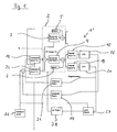
- FIG. 1 the inventive method in exemplary embodiment explained in more detail.
- FIG. 2 correspond with the same reference numerals and will not be explained again.
- a Coriolis gyro 1 ' is additionally provided with an interference unit 26, a demodulation unit 27 and a readout oscillation frequency regulator 28.
- the interference unit 26 generates an alternating signal with a frequency ⁇ mod, which is added to the output signal of a quadrature controller 21 (ie, the force output of the quadrature control).
- the composite signal thus obtained is fed to a (third) modulator 22 whose corresponding output signal is applied to a force transmitter (not shown) and thus to the resonator 2.
- the alternating signal generated by the disturbance modulating unit 26 becomes low "Passage" observed by the resonator 2 in the form of a noise component of the read oscillation tap signal.
- the readout swing tap signal is subjected to a demodulation process performed by a fourth demodulator 19 and supplied to a fourth low-pass filter 20, the output of which applies to both a rotation rate controller 21 and the demodulation unit 27.
- the signal supplied to the demodulation unit 27 is demodulated at a modulation frequency ⁇ mod corresponding to the frequency of the alternating signal generated by the interference unit 26. This determines the interference component or the signal that represents the interference.
- the demodulation unit 27 is therefore to be regarded in this example as an interference signal detection unit.
- An output of the demodulation unit 27 is supplied to the read oscillation frequency controller 28, which adjusts the frequency of the read oscillation in response to it so that the output of the demodulation unit 27, that is, the magnitude of the observed noise component, becomes minimum. If such a minimum is reached, then the frequencies of excitation oscillation and read oscillation substantially coincide.
- the signal supplied to the demodulation unit 27, as an alternative to the signal which is supplied to the rotation rate controller 21, may also be the signal which
- the alternating signal generated by the interference unit 26 can also be added to an output signal of the rotation rate controller 21.
- the signal supplied to the demodulation unit 27 would have to be tapped off at the input or output of the quadrature controller 17.
- the interference signal in this case the alternating signal, but also other interference signals such as band-limited noise
- the quadrature control circuit not just immediately before the third modulator 22, d. H. at any point between the read-out swing tap and the third modulator 22.
- Analogous considerations apply to the case of feeding the noise signal to the rate-of-turn loop.
- the modulation frequency ⁇ mod of the alternating signal is set to a high value after switching on the Coriolis gyro 1 ' to achieve a fast coarse control of the frequency of the read oscillation. Then, it is possible to switch to a relatively low modulation frequency ⁇ mod in order to accurately set a resonance of the read oscillation.
- the amplitude of the modulation frequency ⁇ mod can be greatly reduced after a certain time after the rotation rate controller 21 or the quadrature controller 17 has started. Since the alternating signal at the output of the rotation rate control loop, ie the third control loop is compensated, in general, no notch filter for the modulation frequency ⁇ mod in the rotation rate control loop is required.
- the rotation rate controller 21 simultaneously has the effect that the third demodulator 15 and the fourth demodulator 19 are assigned to the force inputs for the rotation rate control loop (cosine forces) and quadrature control loop (sine forces) in the correct phase.
- the rotation rate (fourth control loop) and quadrature control loop (third control loop) can be separated, even if phase shifts occur in the analog electronics of the Coriolis gyroscope 1 ', which may change due to temperature.
- a high bias will occur in the quadrature closed loop. If this control loop and the yaw rate control loop are not cleanly separated, this bias also appears in the yaw rate control loop.
- the control mechanism described can be used for orthogonalizing quadrature and yaw rate control loops.
- the controlled variable is the reference phase of the third and fourth demodulators 15, 19, which are respectively responsible for quadrature components and rotation rate components of the read oscillation.
- This control preferably takes place digitally in a signal processor (DSP) and renders the Coriolis gyro insensitive to phase shifts in the analogue electronics.
- DSP signal processor
- the resonator of the Coriolis gyroscope is biased so that a) the excitation oscillation remains substantially unaffected, and b) the read oscillation is changed so a readout signal representing the read oscillation contains a corresponding noise component, wherein the frequency of the read oscillation is controlled so that a phase shift between a noise signal that generates the disturbance force, and the noise component contained in the readout signal is as small as possible.
- resonator is here meant the entire oscillatable mass system (or a part thereof) of the Coriolis gyroscope - that is to say the part of the Coriolis gyro designated by reference numeral 2.
- the "turnaround time" of a disturbance that is to say an artificial change of the read oscillation by acting on the resonator with corresponding disturbing forces, by the resonator, ie. H. the time, which elapses from the action of the disturbance on the resonator until the picking up of the disturbance as part of the read-out signal, depends on the frequency of the read oscillation.
- the shift between the phase of the interference signal and the phase of the noise component signal contained in the readout signal is a measure of the frequency of the read oscillation. It can be shown that the phase shift assumes a minimum when the frequency of the read oscillation substantially matches the frequency of the excitation oscillation. Therefore, if one regulates the frequency of the read oscillation so that the phase shift assumes a minimum, then at the same time the frequency of the read oscillation is substantially tuned to the frequency of the excitation oscillation.
- the resonator of the Coriolis gyro is impinged by a disturbing force such that a) the excitation oscillation remains substantially unaffected, and b) the read oscillation is changed so in that a readout signal representing the read oscillation contains a corresponding interference component, the disturbance force being defined as the force which is caused by the signal noise in the readout signal.
- the frequency of the read oscillation is in this case controlled so that the size of the noise component contained in the readout signal, ie the noise component, is as small as possible.
- resonator is understood to mean the entire vibrating mass system of the Coriolis gyro - that is to say the part of the Coriolis gyro marked with reference number 2. It is essential here that the disturbing forces on the resonator only change the read oscillation, but not the excitation oscillation. With reference to Fig. 2 this would mean that the disturbance forces act only on the second resonator 4, but not on the first resonator 3.
- an interference signal in the form of signal noise which occurs directly in the read oscillation tapping signal or at the input of the control circuits (yaw rate control loop / quadrature control loop), becomes stronger after "passage” through the control circuits and the resonator in the read oscillation tap signal, the less the frequency of the read oscillation coincides with the frequency of the excitation oscillation.
- the signal noise which is the signal noise of the read oscillation pickoff electronics or the random walk of the Coriolis gyroscope, acts on the force transmitters after "passing" through the control circuits and thus generates corresponding disturbance forces which act on the resonator and thus cause an artificial change in the read oscillation.
- the "breakdown intensity" of such a disturbance on the read oscillation tap signal is thus a measure of how exactly the frequency of the read oscillation coincides with the frequency of the excitation oscillation.
- the strike-through intensity takes a minimum, i. that the magnitude of the noise component contained in the readout swing tap signal, i. of the noise component, is minimal, so at the same time the frequency of the read oscillation is matched to the frequency of the excitation oscillation.
- the inventive method for electronic tuning of the read oscillation frequency can be combined with the first additional method and / or the second additional method as desired.
- first additional method fast transient response
- second additional method low control process
- Concrete technical configurations as well as further details regarding the methods can be found by the person skilled in the art "Method for electronically tuning the read oscillation frequency of a Coriolis gyro", LTF-191-DE ( DE 102 48 734.4 ) and LTF-192-DE ( DE 102 48 735.4 ) of the same applicant, in each of which the first additional method and the second additional method are described.
Landscapes
- Physics & Mathematics (AREA)
- Engineering & Computer Science (AREA)
- General Physics & Mathematics (AREA)
- Radar, Positioning & Navigation (AREA)
- Remote Sensing (AREA)
- Gyroscopes (AREA)
- Measuring Volume Flow (AREA)
- Flow Control (AREA)
Applications Claiming Priority (3)
| Application Number | Priority Date | Filing Date | Title |
|---|---|---|---|
| DE10248733 | 2002-10-18 | ||
| DE10248733A DE10248733B4 (de) | 2002-10-18 | 2002-10-18 | Verfahren zur elektronischen Abstimmung der Ausleseschwingungsfrequenz eines Corioliskreisels |
| PCT/EP2003/010970 WO2004038331A1 (de) | 2002-10-18 | 2003-10-02 | Verfahren zur elektronischen abstimmung der ausleseschwingungsfrequenz eines corioliskreisels |
Publications (2)
| Publication Number | Publication Date |
|---|---|
| EP1554542A1 EP1554542A1 (de) | 2005-07-20 |
| EP1554542B1 true EP1554542B1 (de) | 2010-06-30 |
Family
ID=32087021
Family Applications (1)
| Application Number | Title | Priority Date | Filing Date |
|---|---|---|---|
| EP03748112A Expired - Lifetime EP1554542B1 (de) | 2002-10-18 | 2003-10-02 | Verfahren zur elektronischen abstimmung der ausleseschwingungsfrequenz eines corioliskreisels |
Country Status (8)
| Country | Link |
|---|---|
| US (1) | US7337665B2 (pl) |
| EP (1) | EP1554542B1 (pl) |
| JP (1) | JP4134040B2 (pl) |
| AT (1) | ATE472714T1 (pl) |
| CA (1) | CA2502326C (pl) |
| DE (2) | DE10248733B4 (pl) |
| PL (1) | PL377569A1 (pl) |
| WO (1) | WO2004038331A1 (pl) |
Families Citing this family (12)
| Publication number | Priority date | Publication date | Assignee | Title |
|---|---|---|---|---|
| DE10248735B4 (de) * | 2002-10-18 | 2004-10-28 | Litef Gmbh | Verfahren zur elektronischen Abstimmung der Ausleseschwingungsfrequenz eines Corioliskreisels |
| FR2849183B1 (fr) * | 2002-12-20 | 2005-03-11 | Thales Sa | Gyrometre vibrant avec asservissement de la frequence de detection sur la frequence d'excitation |
| DE102004026972B4 (de) * | 2004-06-02 | 2015-03-12 | Robert Bosch Gmbh | Drehratensensor mit Frequenznachführung |
| DE102006043412A1 (de) * | 2006-09-15 | 2008-03-27 | Litef Gmbh | Mikroelektromechanischer Sensor sowie Betriebsverfahren für einen mikroelektromechanischen Sensor |
| DE102008044664B4 (de) | 2008-08-28 | 2023-12-21 | Continental Automotive Technologies GmbH | Verfahren zur Frequenzregelung einer Oszillatoranordnung |
| RU2388999C1 (ru) * | 2008-09-01 | 2010-05-10 | Открытое акционерное общество "Концерн "Центральный научно-исследовательский институт "Электроприбор" | Микромеханический гироскоп (варианты) и способы его настройки, основанные на использовании амплитудно-модулированного квадратурного тестового воздействия |
| EP2177875A3 (en) | 2008-10-14 | 2013-04-24 | Watson Industries, Inc. | A Vibrating Structural Gyroscope with Quadrature Control |
| EP2547984B1 (de) | 2010-03-17 | 2014-05-07 | Continental Teves AG & Co. oHG | Verfahren zur entkoppelten regelung der quadratur und der resonanzfrequenz eines mikromechanischen gyroskops |
| KR101803990B1 (ko) * | 2010-03-17 | 2017-12-01 | 콘티넨탈 테베스 아게 운트 코. 오하게 | 시그마-델타 변조에 의해 미소-기계 회전 레이트 센서의 쿼드러쳐 및 공진 주파수의 디커플링된 제어를 위한 방법 |
| FI124624B (en) * | 2012-06-29 | 2014-11-14 | Murata Manufacturing Co | Improved oscillating gyroscope |
| KR101513352B1 (ko) * | 2013-07-22 | 2015-04-17 | 삼성전기주식회사 | 관성센서의 구동장치 및 그 제어방법 |
| US9702697B2 (en) | 2015-02-10 | 2017-07-11 | Northrop Grumman Systems Corporation | Bias and scale-factor error mitigation in a Coriolis vibratory gyroscope system |
Family Cites Families (14)
| Publication number | Priority date | Publication date | Assignee | Title |
|---|---|---|---|---|
| DE4447005A1 (de) * | 1994-12-29 | 1996-07-04 | Bosch Gmbh Robert | Vorrichtung zur Ermittlung einer Drehrate |
| FR2735868B1 (fr) | 1995-06-21 | 1997-08-08 | Asulab Sa | Dispositif de mesure d'une vitesse angulaire |
| FR2736153B1 (fr) * | 1995-06-29 | 1997-08-22 | Asulab Sa | Dispositif de mesure d'une vitesse angulaire |
| FR2749394B1 (fr) * | 1996-05-29 | 1998-08-07 | Sagem | Appareil de mesure de rotation |
| US5992233A (en) * | 1996-05-31 | 1999-11-30 | The Regents Of The University Of California | Micromachined Z-axis vibratory rate gyroscope |
| US6250156B1 (en) * | 1996-05-31 | 2001-06-26 | The Regents Of The University Of California | Dual-mass micromachined vibratory rate gyroscope |
| DE19739903A1 (de) * | 1997-09-11 | 1999-04-01 | Bosch Gmbh Robert | Sensorvorrichtung |
| WO1999019734A2 (en) * | 1997-10-14 | 1999-04-22 | Irvine Sensors Corporation | Multi-element micro gyro |
| DE19853063B4 (de) * | 1997-11-18 | 2011-07-28 | DENSO CORPORATION, Aichi-pref. | Winkelgeschwindigkeitssensor und Diagnosesystem dafür |
| DE19910415B4 (de) * | 1999-03-10 | 2010-12-09 | Robert Bosch Gmbh | Verfahren und Vorrichtung zum Abstimmen eines ersten Oszillators mit einem zweiten Oszillator |
| DE19939998A1 (de) * | 1999-08-24 | 2001-03-01 | Bosch Gmbh Robert | Vorrichtung zur Vorspannungserzeugung für einen schwingenden Drehratensensor |
| DE10062347A1 (de) * | 2000-12-14 | 2002-06-20 | Bosch Gmbh Robert | Verfahren zum Abgleichen des Phasenregelkreises einer elektronischen Auswertevorrichtung sowie eine elektronische Auswertevorrichtung |
| DE10248734B4 (de) * | 2002-10-18 | 2004-10-28 | Litef Gmbh | Verfahren zur elektronischen Abstimmung der Ausleseschwingungsfrequenz eines Corioliskreisels |
| DE10248735B4 (de) * | 2002-10-18 | 2004-10-28 | Litef Gmbh | Verfahren zur elektronischen Abstimmung der Ausleseschwingungsfrequenz eines Corioliskreisels |
-
2002
- 2002-10-18 DE DE10248733A patent/DE10248733B4/de not_active Expired - Fee Related
-
2003
- 2003-10-02 CA CA002502326A patent/CA2502326C/en not_active Expired - Lifetime
- 2003-10-02 PL PL377569A patent/PL377569A1/pl not_active IP Right Cessation
- 2003-10-02 US US10/531,669 patent/US7337665B2/en not_active Expired - Lifetime
- 2003-10-02 DE DE50312850T patent/DE50312850D1/de not_active Expired - Lifetime
- 2003-10-02 WO PCT/EP2003/010970 patent/WO2004038331A1/de not_active Ceased
- 2003-10-02 JP JP2004545795A patent/JP4134040B2/ja not_active Expired - Fee Related
- 2003-10-02 EP EP03748112A patent/EP1554542B1/de not_active Expired - Lifetime
- 2003-10-02 AT AT03748112T patent/ATE472714T1/de not_active IP Right Cessation
Also Published As
| Publication number | Publication date |
|---|---|
| DE50312850D1 (de) | 2010-08-12 |
| CA2502326A1 (en) | 2004-05-06 |
| DE10248733B4 (de) | 2004-10-28 |
| WO2004038331A1 (de) | 2004-05-06 |
| EP1554542A1 (de) | 2005-07-20 |
| US7337665B2 (en) | 2008-03-04 |
| JP4134040B2 (ja) | 2008-08-13 |
| PL377569A1 (pl) | 2006-02-06 |
| CA2502326C (en) | 2009-04-21 |
| JP2006503301A (ja) | 2006-01-26 |
| DE10248733A1 (de) | 2004-05-06 |
| US20060010999A1 (en) | 2006-01-19 |
| ATE472714T1 (de) | 2010-07-15 |
Similar Documents
| Publication | Publication Date | Title |
|---|---|---|
| EP1613925B1 (de) | Verfahren zur kompensation eines nullpunktfehlers in einem corioliskreisel und corioliskreisel mit nullpunktfehlerkompensation | |
| EP1554543B1 (de) | Verfahren zur elektronischen abstimmung der ausleseschwingungsfrequenz eines corioliskreisels | |
| DE69311196T2 (de) | Rauschverminderung für Einachsen-Drehgeschwindigkeitsmessaufnehmer | |
| DE10248733B4 (de) | Verfahren zur elektronischen Abstimmung der Ausleseschwingungsfrequenz eines Corioliskreisels | |
| DE102009000743B4 (de) | Vibrationskompensation für Drehratensensoren | |
| DE60219930T2 (de) | Digitaler breitband-phasenregelkreis (pll) mit halbfrequenzausgang | |
| EP1613926B1 (de) | Verfahren zur ermittlung eines nullpunktfehlers in einem corioliskreisel und corioliskreisel mit nullpunktfehlerermittlung | |
| DE102016204683B3 (de) | Verfahren zur automatischen frequenzanpassung von filtern während des betriebs in geschlossenen regelschleifen | |
| EP1348105B1 (de) | Verfahren zum abgleichen des phasenregelkreises einer elektronischen auswertungsvorrichtung sowie eine elektronische auswertungsvorrichtung | |
| EP1552245B1 (de) | Verfahren zur ermittlung eines nullpunktfehlers eines corioliskreisels und solch ein verfahren verwendender corioliskreisel | |
| WO2005001381A1 (de) | Drehratensensor mit einem vibrationskreisel und verfahren zum abgleich des drehratensensors | |
| EP1554544B1 (de) | Verfahren zur elektronischen abstimmung der ausleseschwingungsfrequenz eines corioliskreisels | |
| DE19710359B4 (de) | Vorrichtung zur Ermittlung einer Bewegungsgröße mit automatischer Schalenfaktornachführung | |
| WO2005003684A1 (de) | Verfahren zum abgleich eines drehratensensors | |
| DE3630619A1 (de) | Optischer ueberlagerungsempfaenger | |
| DE102020202812A1 (de) | Verfahren und Vorrichtung zum verbesserten Betrieb eines Oszillators und Drehratensensor | |
| DE102005043025B4 (de) | Verfahren und Vorrichtung zum Ermitteln einer Drehrate | |
| DE2160087A1 (de) | Mit gyromagnetischer Resonanz arbeitendes Spektrometer | |
| DE2649840A1 (de) | Kreiselmagnetkompass-system | |
| EP0588151A1 (de) | Optischer Heterodynempfänger zum Empfang eines durch differentielle Umtastung der Phase eines Trägerfrequenzsignals erzeugten binär kodierten optischen Signals |
Legal Events
| Date | Code | Title | Description |
|---|---|---|---|
| PUAI | Public reference made under article 153(3) epc to a published international application that has entered the european phase |
Free format text: ORIGINAL CODE: 0009012 |
|
| 17P | Request for examination filed |
Effective date: 20050415 |
|
| AK | Designated contracting states |
Kind code of ref document: A1 Designated state(s): AT BE BG CH CY CZ DE DK EE ES FI FR GB GR HU IE IT LI LU MC NL PT RO SE SI SK TR |
|
| RAP1 | Party data changed (applicant data changed or rights of an application transferred) |
Owner name: NORTHROP GRUMMAN LITEF GMBH |
|
| GRAP | Despatch of communication of intention to grant a patent |
Free format text: ORIGINAL CODE: EPIDOSNIGR1 |
|
| GRAS | Grant fee paid |
Free format text: ORIGINAL CODE: EPIDOSNIGR3 |
|
| GRAA | (expected) grant |
Free format text: ORIGINAL CODE: 0009210 |
|
| AK | Designated contracting states |
Kind code of ref document: B1 Designated state(s): AT BE BG CH CY CZ DE DK EE ES FI FR GB GR HU IE IT LI LU MC NL PT RO SE SI SK TR |
|
| REG | Reference to a national code |
Ref country code: CH Ref legal event code: NV Representative=s name: RENTSCH & PARTNER Ref country code: CH Ref legal event code: EP Ref country code: GB Ref legal event code: FG4D Free format text: NOT ENGLISH |
|
| REG | Reference to a national code |
Ref country code: IE Ref legal event code: FG4D Free format text: LANGUAGE OF EP DOCUMENT: GERMAN |
|
| REF | Corresponds to: |
Ref document number: 50312850 Country of ref document: DE Date of ref document: 20100812 Kind code of ref document: P |
|
| REG | Reference to a national code |
Ref country code: SE Ref legal event code: TRGR |
|
| REG | Reference to a national code |
Ref country code: NL Ref legal event code: VDEP Effective date: 20100630 |
|
| PG25 | Lapsed in a contracting state [announced via postgrant information from national office to epo] |
Ref country code: SI Free format text: LAPSE BECAUSE OF FAILURE TO SUBMIT A TRANSLATION OF THE DESCRIPTION OR TO PAY THE FEE WITHIN THE PRESCRIBED TIME-LIMIT Effective date: 20100630 |
|
| PG25 | Lapsed in a contracting state [announced via postgrant information from national office to epo] |
Ref country code: GR Free format text: LAPSE BECAUSE OF FAILURE TO SUBMIT A TRANSLATION OF THE DESCRIPTION OR TO PAY THE FEE WITHIN THE PRESCRIBED TIME-LIMIT Effective date: 20101001 |
|
| PG25 | Lapsed in a contracting state [announced via postgrant information from national office to epo] |
Ref country code: EE Free format text: LAPSE BECAUSE OF FAILURE TO SUBMIT A TRANSLATION OF THE DESCRIPTION OR TO PAY THE FEE WITHIN THE PRESCRIBED TIME-LIMIT Effective date: 20100630 Ref country code: NL Free format text: LAPSE BECAUSE OF FAILURE TO SUBMIT A TRANSLATION OF THE DESCRIPTION OR TO PAY THE FEE WITHIN THE PRESCRIBED TIME-LIMIT Effective date: 20100630 |
|
| REG | Reference to a national code |
Ref country code: IE Ref legal event code: FD4D |
|
| PG25 | Lapsed in a contracting state [announced via postgrant information from national office to epo] |
Ref country code: RO Free format text: LAPSE BECAUSE OF FAILURE TO SUBMIT A TRANSLATION OF THE DESCRIPTION OR TO PAY THE FEE WITHIN THE PRESCRIBED TIME-LIMIT Effective date: 20100630 Ref country code: CY Free format text: LAPSE BECAUSE OF FAILURE TO SUBMIT A TRANSLATION OF THE DESCRIPTION OR TO PAY THE FEE WITHIN THE PRESCRIBED TIME-LIMIT Effective date: 20100630 Ref country code: CZ Free format text: LAPSE BECAUSE OF FAILURE TO SUBMIT A TRANSLATION OF THE DESCRIPTION OR TO PAY THE FEE WITHIN THE PRESCRIBED TIME-LIMIT Effective date: 20100630 Ref country code: PT Free format text: LAPSE BECAUSE OF FAILURE TO SUBMIT A TRANSLATION OF THE DESCRIPTION OR TO PAY THE FEE WITHIN THE PRESCRIBED TIME-LIMIT Effective date: 20101102 Ref country code: SK Free format text: LAPSE BECAUSE OF FAILURE TO SUBMIT A TRANSLATION OF THE DESCRIPTION OR TO PAY THE FEE WITHIN THE PRESCRIBED TIME-LIMIT Effective date: 20100630 |
|
| PG25 | Lapsed in a contracting state [announced via postgrant information from national office to epo] |
Ref country code: IE Free format text: LAPSE BECAUSE OF FAILURE TO SUBMIT A TRANSLATION OF THE DESCRIPTION OR TO PAY THE FEE WITHIN THE PRESCRIBED TIME-LIMIT Effective date: 20100630 Ref country code: DK Free format text: LAPSE BECAUSE OF FAILURE TO SUBMIT A TRANSLATION OF THE DESCRIPTION OR TO PAY THE FEE WITHIN THE PRESCRIBED TIME-LIMIT Effective date: 20100630 |
|
| BERE | Be: lapsed |
Owner name: NORTHROP GRUMMAN LITEF G.M.B.H. Effective date: 20101031 |
|
| PLBE | No opposition filed within time limit |
Free format text: ORIGINAL CODE: 0009261 |
|
| STAA | Information on the status of an ep patent application or granted ep patent |
Free format text: STATUS: NO OPPOSITION FILED WITHIN TIME LIMIT |
|
| PG25 | Lapsed in a contracting state [announced via postgrant information from national office to epo] |
Ref country code: MC Free format text: LAPSE BECAUSE OF NON-PAYMENT OF DUE FEES Effective date: 20101031 |
|
| 26N | No opposition filed |
Effective date: 20110331 |
|
| PG25 | Lapsed in a contracting state [announced via postgrant information from national office to epo] |
Ref country code: ES Free format text: LAPSE BECAUSE OF FAILURE TO SUBMIT A TRANSLATION OF THE DESCRIPTION OR TO PAY THE FEE WITHIN THE PRESCRIBED TIME-LIMIT Effective date: 20101011 |
|
| REG | Reference to a national code |
Ref country code: CH Ref legal event code: PFA Owner name: NORTHROP GRUMMAN LITEF GMBH Free format text: NORTHROP GRUMMAN LITEF GMBH#LOERRACHER STRASSE 18#79115 FREIBURG (DE) -TRANSFER TO- NORTHROP GRUMMAN LITEF GMBH#LOERRACHER STRASSE 18#79115 FREIBURG (DE) |
|
| REG | Reference to a national code |
Ref country code: DE Ref legal event code: R097 Ref document number: 50312850 Country of ref document: DE Effective date: 20110330 |
|
| PG25 | Lapsed in a contracting state [announced via postgrant information from national office to epo] |
Ref country code: BE Free format text: LAPSE BECAUSE OF NON-PAYMENT OF DUE FEES Effective date: 20101031 |
|
| REG | Reference to a national code |
Ref country code: AT Ref legal event code: MM01 Ref document number: 472714 Country of ref document: AT Kind code of ref document: T Effective date: 20101002 |
|
| PG25 | Lapsed in a contracting state [announced via postgrant information from national office to epo] |
Ref country code: AT Free format text: LAPSE BECAUSE OF NON-PAYMENT OF DUE FEES Effective date: 20101002 |
|
| PG25 | Lapsed in a contracting state [announced via postgrant information from national office to epo] |
Ref country code: LU Free format text: LAPSE BECAUSE OF NON-PAYMENT OF DUE FEES Effective date: 20101002 Ref country code: BG Free format text: LAPSE BECAUSE OF FAILURE TO SUBMIT A TRANSLATION OF THE DESCRIPTION OR TO PAY THE FEE WITHIN THE PRESCRIBED TIME-LIMIT Effective date: 20100630 Ref country code: HU Free format text: LAPSE BECAUSE OF FAILURE TO SUBMIT A TRANSLATION OF THE DESCRIPTION OR TO PAY THE FEE WITHIN THE PRESCRIBED TIME-LIMIT Effective date: 20110101 |
|
| PG25 | Lapsed in a contracting state [announced via postgrant information from national office to epo] |
Ref country code: BG Free format text: LAPSE BECAUSE OF FAILURE TO SUBMIT A TRANSLATION OF THE DESCRIPTION OR TO PAY THE FEE WITHIN THE PRESCRIBED TIME-LIMIT Effective date: 20100930 |
|
| REG | Reference to a national code |
Ref country code: FR Ref legal event code: PLFP Year of fee payment: 13 |
|
| REG | Reference to a national code |
Ref country code: FR Ref legal event code: PLFP Year of fee payment: 14 |
|
| REG | Reference to a national code |
Ref country code: CH Ref legal event code: PCAR Free format text: NEW ADDRESS: BELLERIVESTRASSE 203 POSTFACH, 8034 ZUERICH (CH) |
|
| REG | Reference to a national code |
Ref country code: FR Ref legal event code: PLFP Year of fee payment: 15 |
|
| REG | Reference to a national code |
Ref country code: FR Ref legal event code: PLFP Year of fee payment: 16 |
|
| PGFP | Annual fee paid to national office [announced via postgrant information from national office to epo] |
Ref country code: TR Payment date: 20210928 Year of fee payment: 19 |
|
| PGFP | Annual fee paid to national office [announced via postgrant information from national office to epo] |
Ref country code: GB Payment date: 20211022 Year of fee payment: 19 Ref country code: FI Payment date: 20211019 Year of fee payment: 19 Ref country code: SE Payment date: 20211021 Year of fee payment: 19 Ref country code: DE Payment date: 20211027 Year of fee payment: 19 |
|
| PGFP | Annual fee paid to national office [announced via postgrant information from national office to epo] |
Ref country code: IT Payment date: 20211029 Year of fee payment: 19 Ref country code: FR Payment date: 20211021 Year of fee payment: 19 Ref country code: CH Payment date: 20211022 Year of fee payment: 19 |
|
| REG | Reference to a national code |
Ref country code: DE Ref legal event code: R119 Ref document number: 50312850 Country of ref document: DE |
|
| REG | Reference to a national code |
Ref country code: SE Ref legal event code: EUG |
|
| REG | Reference to a national code |
Ref country code: CH Ref legal event code: PL |
|
| GBPC | Gb: european patent ceased through non-payment of renewal fee |
Effective date: 20221002 |
|
| PG25 | Lapsed in a contracting state [announced via postgrant information from national office to epo] |
Ref country code: LI Free format text: LAPSE BECAUSE OF NON-PAYMENT OF DUE FEES Effective date: 20221031 Ref country code: FR Free format text: LAPSE BECAUSE OF NON-PAYMENT OF DUE FEES Effective date: 20221031 Ref country code: DE Free format text: LAPSE BECAUSE OF NON-PAYMENT OF DUE FEES Effective date: 20230503 Ref country code: CH Free format text: LAPSE BECAUSE OF NON-PAYMENT OF DUE FEES Effective date: 20221031 |
|
| PG25 | Lapsed in a contracting state [announced via postgrant information from national office to epo] |
Ref country code: SE Free format text: LAPSE BECAUSE OF NON-PAYMENT OF DUE FEES Effective date: 20221003 |
|
| PG25 | Lapsed in a contracting state [announced via postgrant information from national office to epo] |
Ref country code: IT Free format text: LAPSE BECAUSE OF NON-PAYMENT OF DUE FEES Effective date: 20221002 Ref country code: GB Free format text: LAPSE BECAUSE OF NON-PAYMENT OF DUE FEES Effective date: 20221002 |
|
| PG25 | Lapsed in a contracting state [announced via postgrant information from national office to epo] |
Ref country code: FI Free format text: LAPSE BECAUSE OF NON-PAYMENT OF DUE FEES Effective date: 20221002 |
|
| PG25 | Lapsed in a contracting state [announced via postgrant information from national office to epo] |
Ref country code: TR Free format text: LAPSE BECAUSE OF NON-PAYMENT OF DUE FEES Effective date: 20221002 |