EP1554545B1 - Systeme de mesure de longueur protege - Google Patents
Systeme de mesure de longueur protege Download PDFInfo
- Publication number
- EP1554545B1 EP1554545B1 EP03753501A EP03753501A EP1554545B1 EP 1554545 B1 EP1554545 B1 EP 1554545B1 EP 03753501 A EP03753501 A EP 03753501A EP 03753501 A EP03753501 A EP 03753501A EP 1554545 B1 EP1554545 B1 EP 1554545B1
- Authority
- EP
- European Patent Office
- Prior art keywords
- scanning head
- scale
- measuring system
- machine
- length measuring
- Prior art date
- Legal status (The legal status is an assumption and is not a legal conclusion. Google has not performed a legal analysis and makes no representation as to the accuracy of the status listed.)
- Expired - Lifetime
Links
Images


Classifications
-
- G—PHYSICS
- G01—MEASURING; TESTING
- G01D—MEASURING NOT SPECIALLY ADAPTED FOR A SPECIFIC VARIABLE; ARRANGEMENTS FOR MEASURING TWO OR MORE VARIABLES NOT COVERED IN A SINGLE OTHER SUBCLASS; TARIFF METERING APPARATUS; MEASURING OR TESTING NOT OTHERWISE PROVIDED FOR
- G01D5/00—Mechanical means for transferring the output of a sensing member; Means for converting the output of a sensing member to another variable where the form or nature of the sensing member does not constrain the means for converting; Transducers not specially adapted for a specific variable
- G01D5/26—Mechanical means for transferring the output of a sensing member; Means for converting the output of a sensing member to another variable where the form or nature of the sensing member does not constrain the means for converting; Transducers not specially adapted for a specific variable characterised by optical transfer means, i.e. using infrared, visible, or ultraviolet light
- G01D5/32—Mechanical means for transferring the output of a sensing member; Means for converting the output of a sensing member to another variable where the form or nature of the sensing member does not constrain the means for converting; Transducers not specially adapted for a specific variable characterised by optical transfer means, i.e. using infrared, visible, or ultraviolet light with attenuation or whole or partial obturation of beams of light
- G01D5/34—Mechanical means for transferring the output of a sensing member; Means for converting the output of a sensing member to another variable where the form or nature of the sensing member does not constrain the means for converting; Transducers not specially adapted for a specific variable characterised by optical transfer means, i.e. using infrared, visible, or ultraviolet light with attenuation or whole or partial obturation of beams of light the beams of light being detected by photocells
- G01D5/347—Mechanical means for transferring the output of a sensing member; Means for converting the output of a sensing member to another variable where the form or nature of the sensing member does not constrain the means for converting; Transducers not specially adapted for a specific variable characterised by optical transfer means, i.e. using infrared, visible, or ultraviolet light with attenuation or whole or partial obturation of beams of light the beams of light being detected by photocells using displacement encoding scales
- G01D5/34746—Linear encoders
- G01D5/34753—Carriages; Driving or coupling means
-
- G—PHYSICS
- G01—MEASURING; TESTING
- G01D—MEASURING NOT SPECIALLY ADAPTED FOR A SPECIFIC VARIABLE; ARRANGEMENTS FOR MEASURING TWO OR MORE VARIABLES NOT COVERED IN A SINGLE OTHER SUBCLASS; TARIFF METERING APPARATUS; MEASURING OR TESTING NOT OTHERWISE PROVIDED FOR
- G01D5/00—Mechanical means for transferring the output of a sensing member; Means for converting the output of a sensing member to another variable where the form or nature of the sensing member does not constrain the means for converting; Transducers not specially adapted for a specific variable
- G01D5/26—Mechanical means for transferring the output of a sensing member; Means for converting the output of a sensing member to another variable where the form or nature of the sensing member does not constrain the means for converting; Transducers not specially adapted for a specific variable characterised by optical transfer means, i.e. using infrared, visible, or ultraviolet light
- G01D5/32—Mechanical means for transferring the output of a sensing member; Means for converting the output of a sensing member to another variable where the form or nature of the sensing member does not constrain the means for converting; Transducers not specially adapted for a specific variable characterised by optical transfer means, i.e. using infrared, visible, or ultraviolet light with attenuation or whole or partial obturation of beams of light
- G01D5/34—Mechanical means for transferring the output of a sensing member; Means for converting the output of a sensing member to another variable where the form or nature of the sensing member does not constrain the means for converting; Transducers not specially adapted for a specific variable characterised by optical transfer means, i.e. using infrared, visible, or ultraviolet light with attenuation or whole or partial obturation of beams of light the beams of light being detected by photocells
- G01D5/347—Mechanical means for transferring the output of a sensing member; Means for converting the output of a sensing member to another variable where the form or nature of the sensing member does not constrain the means for converting; Transducers not specially adapted for a specific variable characterised by optical transfer means, i.e. using infrared, visible, or ultraviolet light with attenuation or whole or partial obturation of beams of light the beams of light being detected by photocells using displacement encoding scales
- G01D5/34746—Linear encoders
Definitions
- the invention relates to a length measuring system according to the preamble of claim 1 and to a method according to claim 9 for the final assembly of such a length measuring system.
- Length measuring systems for measuring relative movements between a first and a second machine part are known and are often used in machine tools, for example, to detect the movement of a machine head or carriage relative to a machine bed. Usually a scale is used for this, which is fastened to the machine bed. A scanning head senses the scale, which can be done without contact as well as contact. However, the higher accuracy of measurement, optical and thus contact-free sensing principles have prevailed.
- the DE 19918 654 A1 describes a generic length measuring system.
- the DE 3 527 652 A1 describes a slightly different pre-assembled magnetic length measuring system.
- Length measuring systems of the type mentioned can be divided into two categories: open and encapsulated measuring systems.
- open measuring systems the scale is openly attached to the machine bed and the scanning head attached to the machine head moves above the scale.
- encapsulated measuring systems the scale lies in a closed capsule in which the scanning head is located. The scanning head runs on lying in the capsule guide elements and is connected to a driver with the machine head, so that it moves with this.
- An encapsulated measuring system is for example in the DE 30 20 003 A1 shown. Also the DE 19 918 654 A1 is dedicated to an encapsulated system.
- Encapsulated measuring systems achieve higher protection against contamination of the scale and the scanning head as open systems, but buy this with a high design effort. Encapsulated measuring systems are accordingly more expensive than open ones.
- the scanning head In open systems, the scanning head is usually fixedly mounted on the machine head, this flexibility is not given, which is why a higher accuracy of the mutual position of the mounting surfaces for scanning head and scale is required. This complicates the final assembly.
- the invention is therefore based on the object to provide a length measuring system in which an improved protection of the scanning head and scale is achieved with reduced technical complexity.
- a profile part which not only has protective functions for the scale, but also surrounds the scanning head, in particular in the area in which optical elements lie.
- the scanning head is fixedly mounted on the machine part, so that it does not require a guide contact with the profile part.
- the profile part can therefore be made simpler in this regard and does not have to lead the scanning head. This follows only the movement of the first machine part to which it is firmly attached.
- the alignment of the scanning head and scale is achieved in the assembled state by appropriate adjustment of the profile part containing the scale to the scanning head.
- the predetermined movement between the first machine part, which carries the scanning head, and the scale-carrying profile part, which is fixed to the second machine part, automatically ensures in the final assembled state for the correct position between the scanning head and scale, as required for an accurate measurement.
- this adjusted condition Prior to final assembly, this adjusted condition is secured by a removable mounting member which removably connects the scanning head to the profile member.
- the attachment of the profile part on the second machine part is carried out in the inventive length measuring expediently when the scanning head and profile part are still connected.
- positive or cohesive connections come into question, wherein a cohesive connection in the form of a bond has the advantage that it can be made by untrained personnel in attaching the length measuring on a machine. It is therefore preferred that the profile part has an adhesive surface on which it is glued to the second machine part.
- the profile part protects the scale. Furthermore, it also has a certain protective function for the scanning head.
- the profile part is profiled in a U-shape with two legs, wherein one of the legs is attached to the second machine part and carries on its inside the scale and the other of the legs surrounds the scanning without contact during the measurement.
- the scale contactless encompassing readhead is usually deep into the profile part, whereby it is particularly well protected.
- the exposed optical components of the scanning head are then preferably in the profile part. This reduces the risk of mechanical damage Damage to the scanning head.
- the risk of contamination for the scale is greatly reduced because it is located inside the U-shaped profile part and in a measuring gap of the scanning head.
- the profile part is formed in this embodiment in the manner of a Kapelsprofils or a U-shaped rail, sitting in the interior of the scale.
- the scanning head can be easily connected to the profile part by a connection between the two legs of the profile part and the scanning head is established.
- This betechnikstelligende mounting elements also have the advantage that the scale lying in the interior of the profile part of the mounting element, which ensures the pre-aligned state, can not be affected.
- a particularly simple yet highly accurate trained mounting element is in the form of two cylindrical cross-section spacers, which are stretched by the legs of the profile part in grooves of the scanning head.
- Such spacers can then be removed without tools in a simple manner by pulling out to release the connection between the scanning head and profile part. Due to the cross section of the spacers and the force exerted by the profile part clamping force beyond the desired adjustment between the scanning and profile part can be adjusted very precisely.
- the profile part is fastened in a preferred embodiment directly on the second machine part.
- the location of the scale in the profile part is thus crucial for the orientation of the scale to the second machine part.
- a high-precision alignment of the scale in the profile part is thus conducive to the measurement accuracy.
- the profile part has a scale-aligning reference surface against which the scale rests in the fastened state.
- a particularly accurate alignment is achieved when using two reference surfaces which are at an angle to each other (preferably 90 °). The reference surfaces align the scale in the profile part.
- a tensioning device which braces the scale in the direction of the reference surface.
- tensioning device comes for example, a spring device or a suitable elastic means, such as a rubber cord in question.
- the scanning head is protected by the standing in the profile part from dirt. He feels the lying in the profile part scale contactless.
- the scanning head which projects into the profile part surrounds the scale fixed there in three sides and without contact during the measurement. This three-sided gripping not only an optical transparency measurement on the scale is possible, which is known for high accuracy, it is also at the same time given a further protection against dirt for the optical elements of the scanning, as these then lie on the flanks of a measuring gap in the the scale is contactless. Soiling of the optical assemblies is thus greatly reduced.
- the length measuring system according to the invention is particularly easy to assemble by first the profile part is aligned and fixed to the second machine part and then the scanning head is attached to the second machine part gap filling.
- the orientation of the profile part should be such that under the relative movement of the first and second machine part, the predetermined adjustment between the scanning head and scale is maintained when the scanning head is guided by the first machine part.
- the orientation of the profile part along the longitudinal axis of the relative movement, ie at a constant distance from the first machine part is essential for the fact that the first machine part to be mounted scanning head and the scale always have the ideal, the smallest possible measuring error conditional length to each other. It is therefore preferred for mounting that the profile part is roughly aligned to the longitudinal axis of the relative movement and then adjusted by means of a teaching along the longitudinal axis at a constant distance from the first machine part, wherein the first and second machine part to Einjust réelle the constant distance are moved against each other. By doing this is ensures that the scanning head is always in a predetermined position to the scale even after attachment to the first machine part.
- the scanning is attached to the first machine part gap filling, it is expedient to set by means of the teaching a predetermined gap between the first machine part and the scanning head before attaching the scanning head on the first machine part.
- the gap-filling attachment then fills this predetermined gap and any deviations caused by tolerances.
- a measuring system with a trained as a scanning head component which can be fastened with a mounting surface using an adhesive to a machine part and which has a mounting plate which is releasably attachable to the machine part and limits the mounting surface with an adhesive volume, in which the adhesive can be filled from above, wherein the adhesive volume is bounded at the bottom and each sealed at the sides between the component and mounting plate for the adhesive.
- the object is further achieved by a method for securing the component of such a measuring system on the machine part, wherein the component is adjusted to a predetermined position on the machine part and fixed there, solved by the fact that after adjustment in the predetermined position, the mounting plate fixedly attached to the machine part and then adhesive is poured into the adhesive volume to firmly connect the component to the mounting plate.
- a mounting plate is used for the measuring system, which is detachably fastened to the machine part and with the mounting surface of the component, for example a scanning head, glued.
- the tolerance requirements of the mounting surface on the machine part are thus significantly reduced, any deviations which could, for example, a wedge-shaped gap on the mounting surface of the scanning head result, are compensated by the bond.
- the adhesive volume formed between the mounting plate and the mounting surface allows a gap-filling attachment of the component to the machine part, so that the attachment of the component has no negative impact on its adjusted position; This particular, since the attachment can be done stress-free by filling the adhesive volume with adhesive.
- the mounting plate on the measuring system beyond a defined material pairing between mounting plate on the one hand and mounting surface on the other hand guaranteed.
- the quality of the bond is thereby increased.
- the mounting plate is detachably attached to the machine part. It is thus possible to detach the component even after the bonding of the machine part. With a bond without a mounting plate, this would not be possible.
- a particularly simple seal can be achieved if the mounting plate or the mounting surface of the component has a protruding structure which seals the adhesive volume between the mounting surface and the mounting plate.
- the mounting surface of the component is approximately rectangular.
- the projecting structure that reaches the seal is U-shaped. Then the adhesive can be filled in at the top of the "U".
- the sealing boundary of the adhesive volume must be ensured even with variations of the gap between the mounting plate and mounting surface. Such variations may be due to tolerances with respect to the mounting surface on the machine part.
- elastic sealing means which still act sufficiently sealing for the adhesive even with a certain variation of the adhesive gap, conceivable.
- a particularly large insensitivity to adhesive gap variations can be achieved by a recess on the mounting surface or the mounting plate, in which the above structure stands for sealing. With this design particularly large tolerances can be allowed for the mounting surface on the machine part.
- the above structure is a sealant, such as a metal bar, a metallic or non-metallic, in particular an elastomeric seal.
- a good attachment for such a sealant results when a recess is provided, in which the sealant is inserted. It is therefore preferable in this respect that the above structure has a sealant inserted in a recess.
- the filling of the adhesive into the gap forming the adhesive volume takes place from above into the adhesive volume, which in most cases will be designed as a gluing bag.
- the mounting plate has a filling hopper feeding the adhesive volume from above.
- this Einyogllichter cooperates with an inlet slope on the component, so that by simply filling the entire amount of adhesive passes directly into the adhesive volume.
- the detachable attachment of the mounting plate allows, as already mentioned, a subsequent removal of the component from the machine part.
- any positive or non-positive connection comes into question.
- the mounting plate has releasable fasteners on the machine part outside the volume one or more mounting holes.
- the component e.g. a scanning head of a length measuring system
- the machine part such as a machine head of a machine tool.
- the thickness of the mounting plate must be considered. It is advantageous in this regard, if the mounting plate is held on the mounting surface during Einjust Schlierens on the component. The same applies to the transport of a component of a measuring system to final assembly. It is therefore preferred that the measuring system has holding means, which serve in particular as a transport lock and with which the mounting plate is removably held on the component.
- the measuring system can be easily attached to the machine part by first adjusting the component, then attaching the mounting plate and then the bonding between the mounting plate and component is made. This ensures a stress-free assembly of the component, whereby the adjusted position remains securely in the final assembly.
- This mounting method is particularly simple when the mounting plate is already held on the mounting surface of the component during the adjustment of the component. It then only has to be attached to the mounting plate on the machine part. The after adjusting the adjusted position between the mounting plate and machine part existing gap is thereby displaced between the mounting plate and the mounting surface of the component, so that there is the desired adhesive gap for the adhesive volume or the adhesive pocket.
- FIG. 1 shows a sectional view through a scale 1 of a length measuring system, which is used on a machine tool to detect the relative movement of a machine head relative to a machine bed.
- the scale 1 is inserted into a capsule profile 2, which surrounds the scale 1 for protection on three sides.
- a receptacle 3 is provided for attaching the scale 1, in which the scale 1 is used (arrow 4).
- a rubber cord 5 is inserted, which acts as a tensioning means to secure the scale 1 in the receptacle 3. Since the scale 1 is sensed later in the measuring process (it has a suitable structuring on this) and its location is important for an accurate measurement, has the Recording 3 via a lower reference surface 6 and a lateral reference surface 7, which align the scale 1 in an exact position in the capsule profile 2 when serving as a clamping means rubber cord 5 pushes the scale 2 on the reference surfaces.
- the capsule profile 2 has a U-shaped cross section with a base 8 and a lid 9. Because the capsule profile 2 surrounds the scale 1 on three sides, a good protection of the sensitive scale 1 is given. The sensed structure of the scale 1 is due to the inclined surface of the scale 1 facing downwards in the installation position, whereby dust deposits are further reduced.
- the base 8 of the capsule profile 2 is designed for attachment to the machine bed of a machine tool.
- FIG. 2 shows the scale 1 installed in the capsule profile 2. It is easy to see that the scale 1 in the capsule profile 2 is accessible only through an opening 10.
- the opening 10 is a slot, as the scale 1 extends perpendicular to the plane of the drawing, as well as the capsule profile 2, which is made of a suitably profiled aluminum strand, for example.
- the legs of the capsule profile 2, i. the base 8 and the cover 9 have retaining grooves so that an upper retaining groove 11 is formed in the cover 9 and a lower retaining groove 12 is formed in the base 8.
- These retaining grooves 11, 12 are used in combination with a certain elasticity of the lid 9 for securing a scanning head inserted into the capsule profile, which will be explained later.
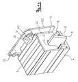
- the scanning head 13 is in FIG. 3 shown schematically. It has a measuring gap 14 which in the assembled state surrounds scale 1 on three sides without contact and on which the measuring means (not shown) are arranged, which sense the structure (also not shown) on scale 1 in a contactless manner.
- the scanning head 13 has a mounting surface 15, with which it is firmly attached to the machine head of the machine tool. Further, the scanning head 13 has an upper groove 16 and a lower groove 17 which cooperate with the retaining grooves 11 and 12 in the legs of the capsule profile 2 so that a transport safety assembly of assembled capsule profile 2 with scale 1 and scanning head 13 is ensured, the Scanning head 13 and the scale 1 are secured to each other in a predetermined, adjusted position.
- an upper fitting cylinder 18 and a lower fitting cylinder 19 are provided whose diameter is dimensioned so that they are inserted into the upper retaining groove 11 and the lower retaining groove 12 by the resilient action of the cover 9 in the groove 16 and 17th are fixed when the scanning head 13 is inserted into the capsule profile 1.
- the fitting cylinders 18 and 19 may be formed, for example, as suitable steel wires.
- the insertion process is in FIG. 3 represented schematically by an arrow, wherein, of course, after the assembly of scale 1 and capsule profile 2, threading of the scale 1 into the measuring gap 14 of the scanning head 13 takes place by a movement perpendicular to the plane of the drawing. That is, the scanning head 13 is slid over the scale 1 at an open end of the capsule profile 2. Thereafter, the fitting cylinder 18 or 19 is inserted into the gap formed by the upper retaining groove 11 and the upper groove 16 and in the gap formed by the lower retaining groove 12 and the lower groove 17. Due to the resilient action of the lid 9 forming leg of the capsule profile 2, the mating cylinder are clamped. The capsule profile 2 holds the scanning head 13 firmly between the base 8 and the lid 9, and there is a predetermined, given within narrow, exactly measured tolerances orientation of the scanning head 13 to scale 1 given.
- the thus preassembled unit of scanning head 13, capsule profile 2 and scale 1 can then be easily mounted on the machine by the scanning head 13 and capsule profile 2 are attached to the machine head or machine bed.
- this attachment according to the in the FIGS. 4 to 7 illustrated steps.
- the figures show a plan view of the preassembled unit of capsule profile 2, scale 1 and scanning head 13 from above (based on FIG. 3 ).
- the scanning head 13 is provided for attachment to the mounting surface 15 with a mounting plate 22, whose construction will be explained later in detail.
- About the mounting plate 22 of the scanning 13 is mounted on the machine part 21.
- the mounting plate 22 must not be provided on the scanning head 13 when attaching the capsule profile 2. It will, as will be explained, only needed for the fixed attachment of the scanning head 13 on the machine head 21.
- the capsule profile 2, inside which the (in the FIGS. 4 to 7 not visible) scale 1 is exactly parallel to the machine sequence, ie aligned to the longitudinal movement of the machine head 1.
- an assembly jig 20 is used, which aligns the capsule profile 2 in a predetermined distance D to the machine head 21.
- FIG. 5 shows this process in which the machine head 21 with mounting jig 20 causes the alignment of the capsule profile 2.
- the adjusted capsule profile 2 is attached to the machine bed.
- the attachment can be done in many ways.
- a two-stage process is used in which first a coarse alignment of the capsule profile 2 to the machine sequence takes place.
- the machine head 21 is moved to the corresponding (end) positions and the capsule profile is aligned with two as far as possible points apart with the mounting jig 20.
- a first fixation of the capsule profile 2 can take place, for example by loosely tightening a screw connection.
- the machine head 21 is moved slowly along the machine cycle with the assembly jig 20 and at the same time the capsule profile 2 is firmly fixed to the machine bed (not shown).
- This can be achieved by firmly tightening the screw in an embodiment in which the capsule profile 2 is screwed.
- the gluing can be carried out in steps, for example by removing a suitable double-sided adhesive tape attached to the base 8 of the capsule profile 2 with the advancing movement of the machine head 21 from a protective sheet, so that the capsule profile 2 is glued firmly to the machine bed.
- the scanning head 13 with the mounting plate 22 attached thereto is as described FIG. 3 has been described, connected by the fitting cylinder 18 and 19 fixed to the capsule profile 2.
- the orientation of the capsule profile 2 parallel to the outlet of the machine head 21 thus has no influence on the pre-adjusted position of capsule profile 2 with scale 1 to the scanning head 13th
- the machine head 21 is moved to the scanning head 16. It turns here between the mounting plate 22, which rests against the mounting surface 15 of the scanning head 13, and the machine head 21, a predetermined gap 45 a. Now, the mounting plate 22, which was previously secured to the scanning head 13, released from this and bolted to the machine part 21. As a result, the gap 45, which previously existed between the mounting plate 22 and machine part 21, displaced between the mounting plate 22 and the scanning head 13. This gap serves as an adhesive gap 30, which is then filled with adhesive to the mounting head 13 fixed to the mounting part 21 bolted mounting plate 22 to install (see FIG. 7 ). The adhesive can harden stress-free.
- connection between the mounting head 13 and capsule profile 2 is achieved by the fitting cylinder 18 and 19 from the through the upper retaining 11th and upper groove 16 and lower retaining groove 12 and lower groove 17 formed columns are pulled out.
- FIG. 8 shows a sectional view through the mounting jig 20. It is placed over the capsule profile 2 and has for this purpose a first reference arm and a second reference arm 24.
- the reference arm 24 has, on its side facing the capsule profile 2, a reference surface 25 which bears against the outside of the capsule profile 2 approximately at the level of the scale 1.
- a support surface 27 which is located on the inside of the first reference arm 23 facing the capsule profile 1, the assembly jig 20 rests on the lid 9 of the capsule profile 2.
- An adjusting arm 26 of the jig 20 ensures that, when the jig 20 is mounted on the capsule profile desired distance D is given to the machine head 21.
- the adjustment arm 26 thus stands between the free ends of the capsule profile 2 and the machine part 21.
- FIG. 9 shows in a sectional view the state of attachment of the measuring system, as in FIG. 7 can be seen in plan view.
- the capsule profile 2 is glued with its base 8 on the machine bed 28, to which an adhesive tape 29 is used with predetermined properties.
- the mounting plate 22 is (on in FIG. 9 not shown) firmly attached to the machine head 21, wherein the gap dimension D, which was specified by the mounting jig 20, a predetermined adhesive gap 30 between the mounting surface 15 of the scanning head 13 and the mounting plate 22 causes.
- the mounting plate 22 has at the bottom a projecting edge projection which limits the adhesive gap 30 down.
- FIG. 10 shows the measuring system after completion of the assembly, wherein the adhesive tape 29 is not shown for simplicity.
- the adhesive gap 30 was filled with adhesive 31, which could not run out of the adhesive gap 30 because of the edge projection 32 on the underside of the mounting plate 22.
- the scanning head 13 is free along the (Placed perpendicular to the plane of the plane) flow direction of the machine head 21 movable.
- the scanning head 13 stands in the capsule profile 2 and is surrounded by this contactless three-sided. As a result, a good protection of the scanning head 13 against contamination or mechanical damage is achieved.
- the scanning head 13 in turn surrounds the scale 1 on three sides and senses this contactlessly. Due to the orientation of the capsule profile 1 and scanning head 13 no guidance of the scanning head 13 in the capsule profile 2 is required. The scanning head 13 is not supported on the capsule profile 2 or scale 1.
- FIG. 11 shows a perspective view of an embodiment of the mounting plate 22, wherein that side in the image to the right, to which the scanning head 13 is attached to the mounting surface 15.
- the mounting plate 22 has a U-shaped peripheral edge projection 32, which serves as a sealant to prevent leakage of the adhesive, which is filled by a formed at the top between the scanning head 13 and the mounting plate 22 opening 34 to the scanning head 13 at to glue the mounting plate 22.
- the mounting plate 22 has a hopper 35 with a filling opening 36 into which adhesive can be injected from a grommet.
- the mounting plate 22 also has two slots 37, which allow to screw the mounting plate 22 on the machine part 21. This screw connection can be solved if the scanning head 13 is to be accepted again by the machine head 21 after bonding has taken place. Without this detachable connection between the mounting plate 22 and the machine head 21, a removal of the scanning head after bonding would only be very complicated and with a risk of damage to the machine head 21 possible.
- One of the elongated holes 27 abei in a flange 38, whereby a particularly good accessibility is achieved even after bonding of the scanning head 13.
- the formation of the holes as slots 37 has the additional advantage that at the corresponding threaded holes on the machine head 21 larger tolerances can be allowed without any impact on the exact assembly of the scanning would be feared.
- the mounting plate 22 In order to secure the mounting plate 22 on the scanning head 13 until the mounting of the mounting plate 22 and the subsequent bonding of the scanning head 13 are completed, the mounting plate 22 has suitable retaining lugs 39 which engage in corresponding holding openings on the scanning head 13. As a result, the mounting plate 22 can be placed on the scanning head 13 and is secured until the end of the attachment against falling.
- the holding openings 42 are on the scanning head 13 in the perspective view of FIG. 12 Good to see that shows the mounting head 13 in a perspective view of the mounting surface 15 ago.
- a U-shaped recess 40 is provided on the mounting surface 15, into which the edge projection 32 of the mounting plate 22 so that a formed between the mounting plate 22 and mounting surface 15 adhesive space 33, which serves to receive the adhesive 31, below and is laterally sealed. Due to the viscosity of the adhesive used, a simple abutment of the edge projection 32 on the vertical wall surface, which is formed by the recess 40, is sufficient to achieve the desired sealing effect.
- the scanning head 13 has for easier filling of the adhesive 31 in the adhesive space 33 via inlet slopes 42.
- the inlet slopes 42 are such that in the hopper 35 filled adhesive via the inlet slope 42 in the adhesive space 33 runs.
- FIG. 13 shows FIG. 13 in which the mounting plate 22 is shown fastened via screws 42 on the machine part 21 (not shown).
- a spout 44 is inserted, which serves to introduce adhesive via the inlet slope 42 in the adhesive space 33 for bonding the scanning head 13 to the mounting plate 22.
- the U-shaped peripheral edge 32 of the mounting plate 22, which protrudes into the recess 40 on the mounting surface 15 of the scanning head 13, ensures that the introduced adhesive can not escape from the adhesive space 33 down or laterally.
- the scanning head 13 is secured during the bonding by the capsule profile 2 in the adjusted position to the machine part 21 (not shown).
- the capsule profile 2 is, however, for better clarity in FIG. 13 not shown.
- FIG. 14 shows the state after bonding just before completion of the final assembly, now the capsule profile 2 together with scale 1 is shown.
- the scanning head 13 is deeply in the capsule profile 2 a.
- the scanning head 14 surrounds the scale 1 on three sides, without resting on this or support itself, when the final assembly is completed, so the fittings were removed.
- the upper fitting cylinder 18 is in FIG. 14 already pulled out of the upper retaining groove 11 and the (hidden in the representation) upper groove 16 of the scanning head 13, the lower fitting cylinder 19 but not yet.
- After removal of the lower fitting cylinder 19 from the lower retaining groove 12 and the lower groove 17 of the scanning head 14 attached to the machine head 21 is freely movable along the scale 1, wherein the movement pattern is predetermined by the movement of the machine head 21.
- the screws 43 can be rotated, whereby the scanning head 13 together with the mounting plate 22 from the machine head 21 is removable.
Landscapes
- Physics & Mathematics (AREA)
- General Physics & Mathematics (AREA)
- Length Measuring Devices With Unspecified Measuring Means (AREA)
- Transmission And Conversion Of Sensor Element Output (AREA)
Abstract
Claims (12)
- Système de mesure de la longueur, pour mesurer les mouvements relatifs entre une première et une deuxième pièce de machine (21, 28), avec une tête de balayage (13) et une échelle graduée (1), dans lequel la tête de balayage (13) peut être montée serrée sur la première pièce de machine (21) pendant un montage final du système de mesure de la longueur, et l'échelle graduée (1) peut être reliée à la deuxième pièce de machine (28), l'échelle graduée (1) est fixée dans une pièce de profil (2) apte à être montée serrée sur la deuxième pièce de machine pendant le montage final et dans laquelle s'introduit la tête de balayage (13), dans lequel le système de mesure de la longueur comporte un élément de montage amovible (18, 19) permettant de prérégler la tête de balayage (13) dans un état prêt au montage final et de la relier de façon détachable à la pièce de profil (2), en reliant deux branches de la pièce de profil (2) à la tête de balayage (13), caractérisé en ce que l'élément de montage comprend deux écarteurs (18, 19) serrés dans des rainures (16, 17) de la tête de balayage (13) au moyen de la pièce de profil (2).
- Système de mesure de la longueur selon la revendication 1, caractérisé en ce que la pièce de profilé (2) comporte une surface de collage, par laquelle elle peut être collée à la deuxième pièce de machine (28).
- Système de mesure de la longueur selon l'une des revendications précédentes, caractérisé en ce que la pièce de profil (2) est profilée en forme de U avec deux branches (8, 9), l'une des deux branches (8) étant montée sur la deuxième pièce de machine et portant l'échelle graduée (1) de son côté intérieur, et l'autre des branches (9) encerclant la tête de balayage (13) sans contact pendant le mesurage.
- Système de mesure de la longueur selon l'une des revendications précédentes, caractérisé en ce que la tête de balayage (13) s'introduit dans la pièce de profil (2) à l'état de montage final, sans s'appuyer dessus.
- Système de mesure de la longueur selon l'une des revendications précédentes, caractérisé en ce que les écarteurs (18, 19) sont cylindriques dans leur section transversale.
- Système de mesure de la longueur selon l'une des revendications précédentes, caractérisé en ce que la pièce de profil (2) comporte une surface de référence (6, 7) pour orienter l'échelle graduée (1), sur laquelle s'applique l'échelle graduée (1) à l'état fixé.
- Système de mesure de la longueur selon la revendication 6, caractérisé par un dispositif de serrage (5) serrant l'échelle graduée (1) dans la direction de la surface de référence (6, 7).
- Système de mesure de la longueur selon l'une des revendications précédentes, caractérisé en ce que la tête de balayage (13) introduite dans la pièce de profil (2) encercle la tête de balayage (1) fixée pendant le mesurage, sur trois côtés et sans contact.
- Procédé pour le montage final d'un système de mesure de la longueur, caractérisé en ce que le système de mesure de la longueur selon la revendication 1 est utilisé, la pièce de profil (2) est orientée et fixée sur la deuxième pièce de machine (28) pour le montage final, la tête de balayage (13) est montée fixement sur la première pièce de machine (21) en remplissant l'espace (31), puis l'élément de montage (18, 19) est éloigné pour défaire la liaison entre la pièce de profil et la tête de balayage.
- Procédé selon la revendication 9, dans lequel la pièce de profil (2) est orientée grossièrement par rapport à l'axe longitudinal du mouvement relatif, puis ajustée par rapport à la première pièce de machine (21) au moyen d'un gabarit, en respectant un espace constant (D) le long de l'axe longitudinal, les première et deuxième pièces de machine (21, 28) étant déplacées l'une contre l'autre pour l'ajustement de l'espace constant.
- Procédé selon la revendication 10, dans lequel un espace (D) est réglé avec le gabarit, pour ainsi créer un espacement prédéterminé entre la première pièce de machine (21) et la tête de balayage (13) avant le montage de la tête de balayage (13) sur la première pièce de machine (28).
- Procédé selon l'une des revendications 9 à 11, dans lequel la tête de balayage (13) et/ou la pièce de profilé (2) sont collées sur chacune des pièces de machine (21, 28).
Applications Claiming Priority (3)
| Application Number | Priority Date | Filing Date | Title |
|---|---|---|---|
| DE10249884A DE10249884B4 (de) | 2002-10-25 | 2002-10-25 | Geschütztes Längenmeßsystem |
| DE10249884 | 2002-10-25 | ||
| PCT/EP2003/010987 WO2004038338A1 (fr) | 2002-10-25 | 2003-10-02 | Systeme de mesure de longueur protege |
Publications (2)
| Publication Number | Publication Date |
|---|---|
| EP1554545A1 EP1554545A1 (fr) | 2005-07-20 |
| EP1554545B1 true EP1554545B1 (fr) | 2011-03-09 |
Family
ID=32103039
Family Applications (1)
| Application Number | Title | Priority Date | Filing Date |
|---|---|---|---|
| EP03753501A Expired - Lifetime EP1554545B1 (fr) | 2002-10-25 | 2003-10-02 | Systeme de mesure de longueur protege |
Country Status (5)
| Country | Link |
|---|---|
| US (1) | US7373852B2 (fr) |
| EP (1) | EP1554545B1 (fr) |
| AU (1) | AU2003271680A1 (fr) |
| DE (1) | DE10262008B4 (fr) |
| WO (1) | WO2004038338A1 (fr) |
Families Citing this family (7)
| Publication number | Priority date | Publication date | Assignee | Title |
|---|---|---|---|---|
| DE102008022312B4 (de) * | 2008-05-06 | 2022-12-01 | Robert Bosch Gmbh | Abtastvorrichtung mit U-förmigem Deckel und Linearlager |
| DE102008043353A1 (de) * | 2008-10-31 | 2010-05-06 | Dr. Johannes Heidenhain Gmbh | Längenmesseinrichtung |
| DE102010030948A1 (de) * | 2010-07-05 | 2012-01-05 | Dr. Johannes Heidenhain Gmbh | Positionsmesssystem und Verfahren zur Montage |
| DE102014006305B4 (de) | 2014-04-30 | 2017-11-23 | Attocube Systems Ag | Optisches Längenmesssystem mit einem interferometrischen Wegsensor zur Integration in Werkzeugmaschinen und Halbleiter-Lithografiesystemen |
| WO2016014047A1 (fr) | 2014-07-23 | 2016-01-28 | Apple Inc. | Processus adaptatifs d'amélioration de l'intégrité de surfaces |
| US10649497B2 (en) * | 2014-07-23 | 2020-05-12 | Apple Inc. | Adaptive processes for improving integrity of surfaces |
| JP6708449B2 (ja) * | 2016-03-22 | 2020-06-10 | 株式会社ミツトヨ | 直線変位測定装置のスケール保持構造 |
Citations (1)
| Publication number | Priority date | Publication date | Assignee | Title |
|---|---|---|---|---|
| DE3527652A1 (de) * | 1984-08-02 | 1986-02-06 | Sokkisha Co., Ltd., Tokio/Tokyo | Befestigungsmechanismus fuer ein messsystem mit magnetskala |
Family Cites Families (15)
| Publication number | Priority date | Publication date | Assignee | Title |
|---|---|---|---|---|
| DE3020003C2 (de) * | 1980-05-24 | 1983-01-27 | Dr. Johannes Heidenhain Gmbh, 8225 Traunreut | Sicherungsvorrichtung für Transport und Montage einer Meßeinrichtung |
| DE8616206U1 (de) | 1986-06-16 | 1986-07-31 | RSF-Elektronik Gesellschaft m.b.H., Tarsdorf | Gekapselte Längenmeßeinrichtung |
| DE3820331A1 (de) * | 1988-06-15 | 1989-12-21 | Heidenhain Gmbh Dr Johannes | Sicherungsvorrichtung fuer eine messeinrichtung |
| JP2625917B2 (ja) * | 1988-07-01 | 1997-07-02 | キヤノン株式会社 | リニアエンコーダ |
| DE3915679A1 (de) * | 1989-05-13 | 1990-11-15 | Heidenhain Gmbh Dr Johannes | Positionsmesseinrichtung mit einer justiervorrichtung |
| DE4017858A1 (de) | 1990-06-02 | 1991-12-12 | Heidenhain Gmbh Dr Johannes | Gekapselte messeinrichtung |
| DE29521403U1 (de) * | 1995-09-14 | 1997-04-10 | Dr. Johannes Heidenhain Gmbh, 83301 Traunreut | Positionsmeßeinrichtung |
| DE69830950T2 (de) * | 1997-05-28 | 2006-05-24 | Sony Manufacturing Systems Corp. | Träger für eine magnetische Skala |
| JP4174096B2 (ja) * | 1998-03-31 | 2008-10-29 | ソニーマニュファクチュアリングシステムズ株式会社 | 位置検出装置 |
| DE19914311A1 (de) * | 1999-03-29 | 2000-10-05 | Heidenhain Gmbh Dr Johannes | Verfahren und Vorrichtung zum Anbringen eines Maßstabes |
| DE19918654B4 (de) * | 1999-04-16 | 2004-07-15 | Dr. Johannes Heidenhain Gmbh | Sicherungsvorrichtung für den Transport und die Montage einer Meßeinrichtung |
| DE10056947A1 (de) * | 2000-11-17 | 2002-05-23 | Optolab Licensing Gmbh | Verfahren und Anordnung zur Montage von Messsystemen |
| DE10059308A1 (de) * | 2000-11-29 | 2002-06-13 | Heidenhain Gmbh Dr Johannes | Verfahren zur Montage eines Längenmessgerät und entsprechendes Längenmessgerät |
| US6820348B2 (en) * | 2001-02-09 | 2004-11-23 | Acu-Rite, Inc. | Mounting tool for linear encoders |
| DE10204611B4 (de) * | 2002-02-05 | 2007-04-05 | Dr. Johannes Heidenhain Gmbh | Verfahren und Vorrichtung zum Anbringen eines Maßstabes oder Maßstabträgers |
-
2002
- 2002-10-25 DE DE10262008A patent/DE10262008B4/de not_active Expired - Fee Related
-
2003
- 2003-10-02 US US10/532,800 patent/US7373852B2/en not_active Expired - Fee Related
- 2003-10-02 EP EP03753501A patent/EP1554545B1/fr not_active Expired - Lifetime
- 2003-10-02 AU AU2003271680A patent/AU2003271680A1/en not_active Abandoned
- 2003-10-02 WO PCT/EP2003/010987 patent/WO2004038338A1/fr not_active Ceased
Patent Citations (1)
| Publication number | Priority date | Publication date | Assignee | Title |
|---|---|---|---|---|
| DE3527652A1 (de) * | 1984-08-02 | 1986-02-06 | Sokkisha Co., Ltd., Tokio/Tokyo | Befestigungsmechanismus fuer ein messsystem mit magnetskala |
Also Published As
| Publication number | Publication date |
|---|---|
| DE10262008B4 (de) | 2010-08-19 |
| DE10262008A1 (de) | 2004-05-13 |
| US7373852B2 (en) | 2008-05-20 |
| EP1554545A1 (fr) | 2005-07-20 |
| AU2003271680A1 (en) | 2004-05-13 |
| US20060162473A1 (en) | 2006-07-27 |
| WO2004038338A1 (fr) | 2004-05-06 |
Similar Documents
| Publication | Publication Date | Title |
|---|---|---|
| DE2712421A1 (de) | Laengenmesseinrichtung mit laengsverschieblichem masstab | |
| EP1554545B1 (fr) | Systeme de mesure de longueur protege | |
| EP0709655A2 (fr) | Guidage | |
| DE10229888B4 (de) | Vorrichtung und Verfahren zum Anbringen eines Maßstabs oder Maßstabträgers oder einer Maßstabführung sowie Maßstab, Maßstabträger oder Maßstabführung oder Schutzband dafür | |
| EP0114251A2 (fr) | Dispositif pour mesurer la longueur | |
| EP1554546B1 (fr) | Systeme de mesure de longueur | |
| DE10013574C2 (de) | Vorrichtung und Verfahren zum lösbaren Befestigen einer Verkleidung an einer Wandung mit definierter Fuge | |
| DE10249882B3 (de) | Meßsystem und Befestigungsverfahren dafür | |
| DE202005004754U1 (de) | Längenmeßsystem | |
| DE19751535A1 (de) | Rahmenanordnung, insbesondere für Bilder | |
| DE3210105C2 (de) | Federelement zur lagerichtigen Befestigung eines Aufnahmekörpers in einem Ausschnitt einer Einbauplatte | |
| EP3798580B1 (fr) | Procédé de fabrication d'un boitier de tête de mesure, couvercle et boitier de tête de mesure | |
| EP0714014B1 (fr) | Niveau à bulle | |
| EP0418212A2 (fr) | Boîtier de protection pour prise de règle et unité de palpage à déplacement longitudinal | |
| DE4130087C2 (fr) | ||
| WO2002064318A1 (fr) | Dispositif de fixation par serrage de pieces, en particulier de toles, sur le parcours d'une chaine de montage | |
| DE29522402U1 (de) | Führung | |
| DE2947786C2 (de) | Anordnung bei einem Elektrizitätszähler zum Befestigen eines Maximumwerkes | |
| DE29807581U1 (de) | Ultraschallwanne | |
| DE102024127482A1 (de) | Höhenverstellbare Gerätehalterung für Fahrzeugschienen | |
| DE8334916U1 (de) | Wasserwaage | |
| DE19655059A1 (de) | Spinnmaschine | |
| DE4209451C5 (de) | Schweißvorrichtung für Kunststoffprofile | |
| DE9112643U1 (de) | Meßwertaufnehmer zur Erfassung von Formänderungen | |
| DE8619361U1 (de) | Handhobel |
Legal Events
| Date | Code | Title | Description |
|---|---|---|---|
| PUAI | Public reference made under article 153(3) epc to a published international application that has entered the european phase |
Free format text: ORIGINAL CODE: 0009012 |
|
| 17P | Request for examination filed |
Effective date: 20050304 |
|
| AK | Designated contracting states |
Kind code of ref document: A1 Designated state(s): AT BE BG CH CY CZ DE DK EE ES FI FR GB GR HU IE IT LI LU MC NL PT RO SE SI SK TR |
|
| AX | Request for extension of the european patent |
Extension state: AL LT LV MK |
|
| DAX | Request for extension of the european patent (deleted) | ||
| RBV | Designated contracting states (corrected) |
Designated state(s): FR GB IT |
|
| RAP1 | Party data changed (applicant data changed or rights of an application transferred) |
Owner name: DR. JOHANNES HEIDENHAIN GMBH |
|
| REG | Reference to a national code |
Ref country code: DE Ref legal event code: 8566 |
|
| 17Q | First examination report despatched |
Effective date: 20070122 |
|
| GRAP | Despatch of communication of intention to grant a patent |
Free format text: ORIGINAL CODE: EPIDOSNIGR1 |
|
| GRAS | Grant fee paid |
Free format text: ORIGINAL CODE: EPIDOSNIGR3 |
|
| GRAA | (expected) grant |
Free format text: ORIGINAL CODE: 0009210 |
|
| AK | Designated contracting states |
Kind code of ref document: B1 Designated state(s): FR GB IT |
|
| REG | Reference to a national code |
Ref country code: GB Ref legal event code: FG4D Free format text: NOT ENGLISH |
|
| PLBE | No opposition filed within time limit |
Free format text: ORIGINAL CODE: 0009261 |
|
| STAA | Information on the status of an ep patent application or granted ep patent |
Free format text: STATUS: NO OPPOSITION FILED WITHIN TIME LIMIT |
|
| 26N | No opposition filed |
Effective date: 20111212 |
|
| REG | Reference to a national code |
Ref country code: FR Ref legal event code: ST Effective date: 20120629 |
|
| PG25 | Lapsed in a contracting state [announced via postgrant information from national office to epo] |
Ref country code: FR Free format text: LAPSE BECAUSE OF NON-PAYMENT OF DUE FEES Effective date: 20111102 |
|
| PGFP | Annual fee paid to national office [announced via postgrant information from national office to epo] |
Ref country code: IT Payment date: 20191028 Year of fee payment: 17 |
|
| PGFP | Annual fee paid to national office [announced via postgrant information from national office to epo] |
Ref country code: GB Payment date: 20191021 Year of fee payment: 17 |
|
| GBPC | Gb: european patent ceased through non-payment of renewal fee |
Effective date: 20201002 |
|
| PG25 | Lapsed in a contracting state [announced via postgrant information from national office to epo] |
Ref country code: GB Free format text: LAPSE BECAUSE OF NON-PAYMENT OF DUE FEES Effective date: 20201002 |
|
| PG25 | Lapsed in a contracting state [announced via postgrant information from national office to epo] |
Ref country code: IT Free format text: LAPSE BECAUSE OF NON-PAYMENT OF DUE FEES Effective date: 20201002 |