EP1554832B1 - Multiplexeur optique a insertion-extraction et structure annulaire pour transmission de donnees a l'aide d'un systeme optique multiplex a repartition en longueur d'ondes - Google Patents
Multiplexeur optique a insertion-extraction et structure annulaire pour transmission de donnees a l'aide d'un systeme optique multiplex a repartition en longueur d'ondes Download PDFInfo
- Publication number
- EP1554832B1 EP1554832B1 EP03773523A EP03773523A EP1554832B1 EP 1554832 B1 EP1554832 B1 EP 1554832B1 EP 03773523 A EP03773523 A EP 03773523A EP 03773523 A EP03773523 A EP 03773523A EP 1554832 B1 EP1554832 B1 EP 1554832B1
- Authority
- EP
- European Patent Office
- Prior art keywords
- optical
- add
- group
- wavelength
- drop multiplexer
- Prior art date
- Legal status (The legal status is an assumption and is not a legal conclusion. Google has not performed a legal analysis and makes no representation as to the accuracy of the status listed.)
- Expired - Lifetime
Links
- 230000003287 optical effect Effects 0.000 title claims abstract description 85
- 238000004891 communication Methods 0.000 claims abstract description 8
- 239000013598 vector Substances 0.000 claims description 29
- 230000005540 biological transmission Effects 0.000 claims description 25
- 238000012544 monitoring process Methods 0.000 description 23
- 239000011159 matrix material Substances 0.000 description 20
- 238000007726 management method Methods 0.000 description 17
- 239000000835 fiber Substances 0.000 description 10
- 230000007246 mechanism Effects 0.000 description 8
- 238000005516 engineering process Methods 0.000 description 7
- 238000000034 method Methods 0.000 description 5
- 230000008569 process Effects 0.000 description 4
- 238000002955 isolation Methods 0.000 description 3
- 230000002457 bidirectional effect Effects 0.000 description 2
- 238000010586 diagram Methods 0.000 description 2
- 229910052691 Erbium Inorganic materials 0.000 description 1
- 230000003321 amplification Effects 0.000 description 1
- 238000006243 chemical reaction Methods 0.000 description 1
- 230000000295 complement effect Effects 0.000 description 1
- 230000001419 dependent effect Effects 0.000 description 1
- UYAHIZSMUZPPFV-UHFFFAOYSA-N erbium Chemical compound [Er] UYAHIZSMUZPPFV-UHFFFAOYSA-N 0.000 description 1
- 238000005286 illumination Methods 0.000 description 1
- 238000003199 nucleic acid amplification method Methods 0.000 description 1
- 239000013307 optical fiber Substances 0.000 description 1
- 230000035484 reaction time Effects 0.000 description 1
- 230000009467 reduction Effects 0.000 description 1
- 230000008439 repair process Effects 0.000 description 1
Images
Classifications
-
- H—ELECTRICITY
- H04—ELECTRIC COMMUNICATION TECHNIQUE
- H04J—MULTIPLEX COMMUNICATION
- H04J14/00—Optical multiplex systems
- H04J14/02—Wavelength-division multiplex systems
- H04J14/0287—Protection in WDM systems
- H04J14/0289—Optical multiplex section protection
- H04J14/0291—Shared protection at the optical multiplex section (1:1, n:m)
-
- H—ELECTRICITY
- H04—ELECTRIC COMMUNICATION TECHNIQUE
- H04J—MULTIPLEX COMMUNICATION
- H04J14/00—Optical multiplex systems
- H04J14/02—Wavelength-division multiplex systems
- H04J14/0201—Add-and-drop multiplexing
- H04J14/0202—Arrangements therefor
- H04J14/0206—Express channels arrangements
-
- H—ELECTRICITY
- H04—ELECTRIC COMMUNICATION TECHNIQUE
- H04J—MULTIPLEX COMMUNICATION
- H04J14/00—Optical multiplex systems
- H04J14/02—Wavelength-division multiplex systems
- H04J14/0201—Add-and-drop multiplexing
- H04J14/0202—Arrangements therefor
- H04J14/0209—Multi-stage arrangements, e.g. by cascading multiplexers or demultiplexers
-
- H—ELECTRICITY
- H04—ELECTRIC COMMUNICATION TECHNIQUE
- H04J—MULTIPLEX COMMUNICATION
- H04J14/00—Optical multiplex systems
- H04J14/02—Wavelength-division multiplex systems
- H04J14/0201—Add-and-drop multiplexing
- H04J14/0202—Arrangements therefor
- H04J14/0213—Groups of channels or wave bands arrangements
-
- H—ELECTRICITY
- H04—ELECTRIC COMMUNICATION TECHNIQUE
- H04J—MULTIPLEX COMMUNICATION
- H04J14/00—Optical multiplex systems
- H04J14/02—Wavelength-division multiplex systems
- H04J14/0201—Add-and-drop multiplexing
- H04J14/0215—Architecture aspects
- H04J14/0216—Bidirectional architectures
-
- H—ELECTRICITY
- H04—ELECTRIC COMMUNICATION TECHNIQUE
- H04J—MULTIPLEX COMMUNICATION
- H04J14/00—Optical multiplex systems
- H04J14/02—Wavelength-division multiplex systems
- H04J14/0227—Operation, administration, maintenance or provisioning [OAMP] of WDM networks, e.g. media access, routing or wavelength allocation
- H04J14/0241—Wavelength allocation for communications one-to-one, e.g. unicasting wavelengths
- H04J14/0242—Wavelength allocation for communications one-to-one, e.g. unicasting wavelengths in WDM-PON
- H04J14/0245—Wavelength allocation for communications one-to-one, e.g. unicasting wavelengths in WDM-PON for downstream transmission, e.g. optical line terminal [OLT] to ONU
- H04J14/0246—Wavelength allocation for communications one-to-one, e.g. unicasting wavelengths in WDM-PON for downstream transmission, e.g. optical line terminal [OLT] to ONU using one wavelength per ONU
-
- H—ELECTRICITY
- H04—ELECTRIC COMMUNICATION TECHNIQUE
- H04J—MULTIPLEX COMMUNICATION
- H04J14/00—Optical multiplex systems
- H04J14/02—Wavelength-division multiplex systems
- H04J14/0278—WDM optical network architectures
- H04J14/0283—WDM ring architectures
-
- H—ELECTRICITY
- H04—ELECTRIC COMMUNICATION TECHNIQUE
- H04Q—SELECTING
- H04Q11/00—Selecting arrangements for multiplex systems
- H04Q11/0001—Selecting arrangements for multiplex systems using optical switching
- H04Q11/0005—Switch and router aspects
-
- H—ELECTRICITY
- H04—ELECTRIC COMMUNICATION TECHNIQUE
- H04J—MULTIPLEX COMMUNICATION
- H04J14/00—Optical multiplex systems
- H04J14/02—Wavelength-division multiplex systems
- H04J14/0227—Operation, administration, maintenance or provisioning [OAMP] of WDM networks, e.g. media access, routing or wavelength allocation
-
- H—ELECTRICITY
- H04—ELECTRIC COMMUNICATION TECHNIQUE
- H04Q—SELECTING
- H04Q11/00—Selecting arrangements for multiplex systems
- H04Q11/0001—Selecting arrangements for multiplex systems using optical switching
- H04Q11/0005—Switch and router aspects
- H04Q2011/0007—Construction
- H04Q2011/0016—Construction using wavelength multiplexing or demultiplexing
-
- H—ELECTRICITY
- H04—ELECTRIC COMMUNICATION TECHNIQUE
- H04Q—SELECTING
- H04Q11/00—Selecting arrangements for multiplex systems
- H04Q11/0001—Selecting arrangements for multiplex systems using optical switching
- H04Q11/0062—Network aspects
- H04Q2011/0075—Wavelength grouping or hierarchical aspects
Definitions
- the invention relates to an optical add / drop multiplexer for realizing a wavelength division multiplexed optical communication ring network and a ring structure using such an optical add / drop multiplexer.
- SDH technology offers certain protection mechanisms that are able to switch individual SDH services to alternative routes.
- the transmission capacity of SDH technology is limited by the data rates that can be realized today.
- customers increasingly demand data services based on SDH-foreign applications.
- DWDM technology offers a solution perspective here.
- DWDM DWDM-based network
- SDH services can transmit one or more SDH services as well as other applications such as IP, video or SAN applications.
- a DWDM-based network is characterized by increased capacity and application transparency compared to a pure SDH network. As a DWDM network usually does not depend on the protection mechanisms of the SDH Technology, it is necessary, together with the DWDM technology, to introduce new protection mechanisms.
- DWDM technology today is based on protocol-transparent transmission by so-called transponder or channel cards, in principle only switching criteria are available for DWDM protection mechanisms that use parameters of the optical layer.
- Typical switching criteria are "Loss Of Light” (LOL) and “Loss Of Clock” (LOC). That is to say, light levels or light modulation at a port of the system to be defined have disappeared. As a result, the traffic corresponding to this port is switched to a replacement route.
- channels are grouped in a DWDM system. Accordingly, there are usually two filter stages: a group and a channel filter stage. A group typically includes four or eight channels. The applications are finally terminated on wavelength-specific channel cards. Here, an optical / electrical or electrical / optical conversion of the signals takes place.
- DWDM ring networks are typically implemented as bi-directional optical fiber (O-BLSR) with path protection.
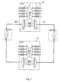
- Fig. 1 shows the example of a 4-node ring network 1, the fully redundant configuration of the entire path.
- Group filter 3, channel filter 5 and channel card 7 are redundantly configured in each node for OST and WEST direction. In case of failure, the channel cards switch to the other direction.
- the nodes of the ring network 1 formed by the add / drop multiplexers 9 provide "pass through” and "add / drop” functionality for different portions of the traffic.
- the different traffic relationships of a DWDM ring are assigned specific wavelength groups. The reason for this lies in the optical parameters:
- the main task of the filters of a DWDM system is to isolate wavelengths as sharply as possible from one another. Two adjacent wavelengths undergo a certain finite isolation in a channel filter. The isolation between non-adjacent wavelengths is higher. Particularly high is the isolation between wavelengths that belong to different groups. All applications which pass through the same geometric traffic relationship within a ring (eg, as in FIG. 1 from node 1 to node 3), have approximately the same optical power values at all points of the path.
- wavelengths of such a traffic relationship are therefore relatively easy to separate.
- wavelengths that belong to different traffic relationships may be difficult to separate from each other due to potentially very different performance values and must be strongly isolated from each other.
- Nodes are therefore terminated or forwarded whole groups (add / drop or pass through). Pass Through for a wavelength group can either be purely passive or with simultaneous amplification by an optical amplifier EDFA (erbium doped fiber amplifier).
- EDFA optical amplifier
- the protection mechanism of path protection happens at the level of the channel cards.
- a WEST side channel card detects LOS or LOC, it switches to a replacement OST side card. Switching occurs through direct communication between two cards without going through an operating system and is therefore faster than the typically required 50 ms.
- Loss of a line-side receive signal (LOS of the Remote Rx) also leads to the immediate shutdown of the line-side transmitter (Remote Tx), thus ensuring laser class 1.
- LOS of the Remote Rx also leads to the immediate shutdown of the line-side transmitter (Remote Tx), thus ensuring laser class 1.
- the transmitters of the Working and Protection card are turned on, which is a permanent Monitoring both routes represents.
- EP-A-0 905 936 discloses an optical add / drop multiplexer for realizing a ring structure having a first (west side) and a second (east side) optical group wavelength division multiplexer / demultiplexer unit each having a wavelength division multiplexed signal fed thereto into a plurality of multiplexed optical group signals demultiplexing and multiplexing a plurality of multiplexed optical signals supplied thereto to an outgoing optical wave multiplexed signal, wherein a part of the multiplexed optical signals are supplied to the group multiplexed signal ports of the other wavelength division multiplexer / demultiplexer unit and to a control unit.
- the demultiplexed channel signals are supplied to an optical "cross-connect". This "cross-connect" allows the dropping and adding of individual channels in the respective node.
- the present invention seeks to provide an optical add / drop multiplexer for implementing an optical wavelength division multiplex communication ring network and a ring structure using such an optical add / drop multiplexer, with the least possible effort sufficient Operational security for the communication ring network is ensured.
- the invention is based on the recognition that by switching groups of wavelength channels (ring group switching, RGS) on the optical layer in relation to the full path protection, a drastic reduction of the hardware expenditure is reached. It can be shown that for normal ring networks in the metro area, even with such a structure, sufficient network availability can be achieved.
- RGS ring group switching
- RCS Ring Group Switching
- the add / drop multiplexer comprises at least one optical supervisory channel (OSC) transceiver unit which serves to transmit management information within the ring structure.
- the transmission of the management information may be done either directly between the add / drop multiplexers or via a network management controller.
- OSC optical supervisory channel
- the information required for effecting the switching operations by means of the at least one group switch unit can be transmitted to each add / drop multiplexer.
- the respective add / drop multiplexer can either be informed directly, which switching operation is to be performed, or merely the required information about the state of the transmission paths, wherein the control unit of the add / drop multiplexer determines and executes the necessary switching operations themselves.
- control unit of each add / drop multiplexer is connected to the control units of all other add / drop multiplexers and / or the network management control unit by means of the management channel and Internet Protocol (IP).
- IP Internet Protocol
- the control unit enters the information about the operability of the east and west transmission link in two bits of a link vector and transmits the link vector to the other add / drop multiplexer and / or the network management control unit.
- the operations of writing / reading the link vector and determining the required switching operations from the link vector and the traffic relations within the ring network known to the node or add / drop multiplexer are preferably carried out in the control unit directly, i. without the influence of an operating system.
- the read or write operation of the link vector preferably takes place between the layer 3 and the MAC layer 2, wherein the control unit enters the link vector in a proprietary frame between two MAC frames.
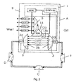
- Fig. 2 shows schematically the use of optical group switching units for protecting the data transmission channels in a WDM ring network.
- the ring network has four nodes A, B, C and D in the illustrated embodiment.
- Each node is formed by an add / drop multiplier 9 whose internal structure is shown in FIG. 2 using the example of node A.
- the add / drop multiplexer 9 comprises two group filters or wavelength division multiplexer / demultiplexer units 3, the multiplex ports 3a of which are respectively connected via a monitoring channel filter unit OSF to the west-side or east-side link of the transmission medium.
- a monitoring channel filter unit OSF to the west-side or east-side link of the transmission medium.
- One or two optical waveguides preferably single-mode fibers, serve as the transmission medium, depending on whether the data traffic is unidirectional via an optical waveguide or bidirectionally over a single optical waveguide.
- the monitoring channel filter units OSF filter out of the respective received multiplex signal, which also includes the individual optical payload channels, out the wavelength of the monitoring channel and supply this received signal of the monitoring channel to a monitoring channel module OSCM-RGS.
- the monitoring channel module OSCM-RGS is part of the control unit 1 of the add / drop multiplexer 9, which also includes the network management control unit NEMI.
- the monitoring channel module OSCM-RGS feeds the transmission signal of the monitoring channel to the monitoring channel filter units OSF, which couple this transmission signal into the east and west-side link or optical waveguide.
- the monitoring channel module has two transceiver cards or monitoring channel cards.
- the actual core of the monitoring channel module OSCM-RGS is preferably realized as an FPGA (Field Programmable Gate Array), so that the actions of the OSCM RGS are very fast and are not slowed down by a relatively slow-acting operating system.
- Each link between two nodes is thus acted upon in each direction by the optical monitoring channel signal of the respective transceiver card, so that the respective adjacent node can determine from the signal of the monitoring channel, whether the link is functional or not. As already explained, this can be done by detecting the "Loss of Light” (LOL) or “Loss of Clock” (LOC).
- LLOL Light
- LOC Lock
- the demultiplexed group multiplexed signals are applied at the group multiplexed signal ports 3b of the wavelength division multiplexer / demultiplexer units 3 to apply the demultiplexed group multiplexed signals. These are looped through either directly or via optical amplifiers EDFA to the relevant group multiplex signal ports 3b of the other wavelength multiplexer / demultiplexer units 3. Only those group multiplexed signals that are intended for termination in the respective add / drop multiplexer are each supplied to a switched port 13a or 13b of a group switching unit 13. In the exemplary embodiment illustrated in FIG. 2, only a single wavelength group in the add / drop multiplexer 9 of node A is terminated.
- the received group multiplex signal is supplied from the group switch unit 13 (RGSM) to the multiplex port of a channel filter unit 5, which separates the individual, in the illustrated example four, optical channels of the group multiplex signal and respectively a transceiver or channel card WCM1 to WCM4 supplies.
- RGSM group switch unit 13
- the optical signals respectively transmitted from the channel cards WCM1 to WCM4 are combined by the channel filter unit into a multiplexed optical signal and supplied to the group switching unit 13. This then feeds the group multiplexed signal to either the east or west wavelength multiplexer / demultiplexer unit 3.
- the filter units 3, 5 and OSF can be realized as purely passive optical couplers, for example AWGs.
- the group switch unit 13 can also comprise, in addition to a controllable 1x2 optical switch, a unit for determining the required switch state.
- the group switch unit 13 receives from the monitoring channel module OSCM-RGS of the control unit 1 the information as to which state the individual links of the ring network have, and from the network management unit NEMI the information as to which traffic relationships within the ring network are actually to be realized. From this, it can then be determined within the group switch unit which switching state has to be assumed. The reception and transmission paths are always switched simultaneously.
- the logical concept of using group switch units is based on the optical switching of individual traffic relationships of an optical ring network.
- Each traffic relationship has its own switching criterion, which depends on the routing in the ring.
- these switching criteria and the influence of switchings on the traffic routing in the ring are to be defined generically.
- the number of ring nodes N can in principle scale from 2 to as high as desired. In practice, N is not greater than the number of available wavelength groups.
- link vector L link vector L
- switch matrix S traffic matrix T.
- a ring with N nodes has N fiber optic cuts or links between the nodes.
- Each link can either be interruption-free ("up") or interrupted ("down”).
- the N-dimensional link vector characterizes the state of the set of all links in a ring.
- Each element of the link vector can take the value zero for "down” or the value one for "up”.
- the state L [0; 1; 1; 1] means, for example, that the direct connection between nodes 1 and 2 has failed.
- the link vector is transported over the monitoring channel, which is shown in dotted lines in FIG.
- a single ring node has the status of the link immediately to the east or directly to the west, as seen from the node.
- Each node can thus describe two bits of the link vector.
- This functionality of describing and evaluating the link vector is implemented in the monitoring channel module OSCM-RGS.
- the monitoring channel typically uses Ethernet to span an IP network between the network nodes interconnecting the network management units NEMI of all the nodes. This makes central management of the entire network possible from a "gateway" node (of course, central management can also be performed by a separate control unit connected to the nodes).
- the read or write operation of the link vector does not take place on IP layer 3, but already between layer 3 and MAC layer 2. The reason for this is that only below Layer 3 fixed defined switching times of less than 50 ms can be realized. So the link vector is written into a proprietary frame between two MAC frames. The extra frame contains a start and a stop bit in addition to the link vector. Depending on the number of nodes in the ring, it has a length of ( N + 2) bits.
- the maximum length of a MAC frame can be up to 65536 bits. At a data rate of 125 Mbps, this corresponds to a time of less than 1 ms between two link vectors. The transmission rate of the "switching criterion link vector" achieved in this way is therefore sufficient to also switch SDH services.
- the switch matrix S describes and controls the state of all group switch units in the ring.
- the switch matrix is of rank ( N ⁇ N ).
- the basis of the switch matrix will be spanned by the OST and WEST terminals of the network nodes. That is, a group switch unit that switches a traffic relation between the nodes 1 and 2 is represented by the elements S 21 and S 12 . Both elements are always complementary.
- the switch matrix is unique to the link vector.
- the information about the traffic relationship to be switched is supplied by the network management unit NEMI and is part of the configuration data of the management.
- NEMI Network Management unit
- the link vector is transmitted with a fixedly defined high time resolution.
- the relevant switching bit S ij is generated in the group switch unit 13 by a simple arithmetic operation, which controls the optical switch directly.
- connection to the network management unit NEMI is usually established via a system-internal bus and the system-internal management operating system
- connection to the OSCM RGS is hardwired and does not make the slow detour via an operating system.
- the traffic matrix T describes all the traffic in the ring. It has the same basis as the switch matrix. Each entry in the traffic matrix other than zero means that, depending on the location of the entry in the matrix, traffic is exchanged between two nodes.
- Each element contains information about the wavelength group occupied for the corresponding traffic relationship as well as the exact assignment of the individual wavelength channels with applications. As long as all links of a ring are uninterrupted (left are "up"), each node can be reached via two independent routes: either from the east or from the west. The traffic matrix is therefore not unique. Only the state of the switch matrix provides a clear routing in the ring.
- T 1 EAST 2 EAST ⁇ N EAST 1 WEST T 11 T 12 ⁇ T 1 ⁇ N 2 WEST T 21 T 22 ⁇ T 2 ⁇ N M M M O M N WEST T N ⁇ 1 T N ⁇ 2 ⁇ T NN
- T ij S ij ⁇ T ij '
- the link vector is transported to all nodes of the ring.
- the link vector is isolated from the MAC frames and two bits are overwritten to update the state of the links west and east of the node.
- the thus updated link vector is passed to the group switch unit.
- the link vector is translated into a switch bit. If a fault occurs in the ring, the group switch unit decides whether the corresponding wavelength group must be switched from the OST to the WEST terminal or vice versa.
- the optical switch of the group switch unit switches transmitting and receiving direction in parallel.
- the network management unit NEMI supplies configuration data to the monitoring channel module OSCM-RGS or the group switch unit RGS and, on the other hand, matches the traffic matrix with the switch matrix. While the link vector and switch matrix directly influence the traffic in the ring, the traffic matrix has no influence on the traffic and serves only to display all data streams in the ring.
Landscapes
- Engineering & Computer Science (AREA)
- Computer Networks & Wireless Communication (AREA)
- Signal Processing (AREA)
- Optical Communication System (AREA)
- Small-Scale Networks (AREA)
Claims (13)
- Multiplexeur optique à insertion/extraction pour réaliser un réseau annulaire de communication optique multiplex à répartition en longueurs d'onde, comprenant :a) une première (côté ouest) et une seconde (côté est) unité optique de multiplexeur/démultiplexeur à répartition en longueurs d'onde groupées, qui, respectivement, démultiplexent un signal multiplexé en longueurs d'onde qui leur a été transmis en plusieurs signaux optiques multiplexés groupés et/ou qui multiplexent plusieurs signaux optiques multiplexés groupés qui leur ont été transmis en un signal optique multiplexé en longueurs d'onde sortant,b) dans lequel une partie des signaux optiques multiplexés groupés est transmise aux ports des signaux multiplexés groupés des autres unités respectives de multiplexeur/démultiplexeur à répartition en longueurs d'onde,c) comprenant au moins une unité de multiplexeur à canal, à laquelle un signal optique multiplexé groupé peut être transmis, qui démultiplexe celui-ci en signaux optiques utiles individuels qu'elle transmet respectivement à une unité optique d'émetteur-récepteur et qui multiplexe les signaux optiques utiles envoyés par les unités optiques d'émetteur-récepteur en un signal optique multiplexé groupé,d) dans lequel le port de signal multiplexé groupé de la au moins une unité de multiplexeur à canal peut être connecté au moyen d'une unité optique de commutation groupée à un port de signal multiplexé groupé de la première ou de la seconde unité optique de multiplexeur/démultiplexeur à répartition en longueurs d'onde groupées,e) comprenant une unité de commande pour commander la au moins une unité optique de commutation groupée etf) comprenant une unité de filtrage à canal de surveillance côté est et côté ouest (OSF) qui sépare respectivement par filgrage du signal multiplexé en longueurs d'onde côté est et côté ouest, le signal d'un canal de gestion servant à transmettre les informations de gestion à l'intérieur de la structure annulaire et le transmet à l'unité de commande ou qui transmet le signal du canal de gestion de l'unité de commande au signal multiplexé en longueurs d'onde.
- Multiplexeur à insertion/extraction selon la revendication 1, caractérisé en ce que l'unité de commande détecte une interférence du segment de transmission côté est et côté ouest et utilise cette information pour commander la au moins une unité de commutation groupée.
- Multiplexeur à insertion/extraction selon la revendication 2, caractérisé en ce que l'unité de commande interprète le segment de transmission concerné comme brouillé lorsqu'on ne détecte absolument aucune puissance de réception optique ou absolument aucune modulation d'un signal porteur optique.
- Multiplexeur à insertion/extraction selon l'une quelconque des revendications précédentes, caractérisé en ce que l'on prévoit au moins une unité d'émetteur-récepteur pour le canal de gestion.
- Multiplexeur à insertion/extraction selon la revendication 4, caractérisé en ce qu'une longueur d'onde séparée est affectée au canal de gestion.
- Multiplexeur à insertion/extraction selon la revendication 5, caractérisé en ce que le signal du canal de gestion est respectivement extrait du bus optique et injecté dans celui-ci au moyen d'un filtre optique séparé, qui est connecté au port multiplex des unités optiques de multiplexeur/démultiplexeur à répartition en longueurs d'onde groupées.
- Multiplexeur à insertion/extraction selon l'une quelconque des revendications 4 à 6, caractérisé en ce que le signal porteur du canal de gestion est transmis en permanence au multiplexeur à insertion/extraction respectivement voisin.
- Multiplexeur à insertion/extraction selon l'une quelconque des revendications 4 à 7, caractérisé en ce que deux unités d'émetteur-récepteur sont prévues pour créer un canal de gestion entre le multiplexeur à insertion/extraction respectif et les multiplexeurs à insertion/extraction respectivement voisins côté est et côté ouest.
- Structure annulaire autorégénératrice pour la transmission optique d'informations dans le multiplexeur à répartition de longueurs d'onde,a) dans laquelle chaque noeud annulaire est constitué d'un multiplexeur à insertion/extraction selon l'une quelconque des revendications précédentes,b) dans laquelle chaque multiplexeur à insertion/extraction est connecté via au moins un guide d'ondes optiques à respectivement un multiplexeur à insertion/extraction côté est et à un multiplexeur à insertion/extraction côté ouest.
- Structure annulaire selon la revendication 9, caractérisée en ce que l'unité de commande de chaque multiplexeur à insertion/extraction détecte une interférence du segment de transmission côté est et côté ouest et transmet cette information, directement ou via une unité de commande centrale de gestion du réseau, à tous les autres multiplexeurs à insertion/extraction respectifs et en ce que l'unité de commande de chaque multiplexeur à insertion/extraction utilise ces informations pour commander la au moins une unité de commutation groupée pour permettre des connexions de communication prédéterminées entre le multiplexeur à insertion/extraction concerné et au moins un autre multiplexeur à insertion/extraction.
- Structure annulaire selon la revendication 10, caractérisée en ce que l'unité de commande de chaque multiplexeur à insertion/extraction est connectée, au moyen du canal de gestion et du protocole Internet IP, aux unités de commande de tous les autres multiplexeurs à insertion/extraction et/ou à l'unité de commande de gestion du réseau.
- Structure annulaire selon la revendication 10 ou 11, caractérisée en ce que l'unité de commande encode l'information sur le fonctionnement du segment de transmission côté est et côté ouest dans deux bits d'un vecteur de liaison et en ce qu'elle transmet le vecteur de liaison aux autres multiplexeurs à insertion/extraction et/ou à l'unité de commande de gestion du réseau.
- Structure annulaire selon la revendication 12, caractérisée en ce que l'opération de lecture ou d'écriture du vecteur de liaison se fait entre la couche 3 et la couche MAC 2, l'unité de commande insérant le vecteur de liaison dans une trame propriétaire entre deux trames MAC.
Applications Claiming Priority (5)
| Application Number | Priority Date | Filing Date | Title |
|---|---|---|---|
| DE10248059 | 2002-10-15 | ||
| DE10248059A DE10248059A1 (de) | 2002-10-15 | 2002-10-15 | Optischer Add/Drop-Multiplexer und Ringstruktur zur Datenübertragung mittels eines optischen Wellenlängenmultiplex-Systems |
| DE20215841U | 2002-10-15 | ||
| DE20215841U DE20215841U1 (de) | 2002-10-15 | 2002-10-15 | Optischer Add/Drop-Multiplexer und Ringstruktur zur Datenübertragung mittels eines optischen Wellenlängenmultiplex-Systems |
| PCT/DE2003/003408 WO2004036801A1 (fr) | 2002-10-15 | 2003-10-14 | Multiplexeur optique a insertion-extraction et structure annulaire pour transmission de donnees a l'aide d'un systeme optique multiplex a repartition en longueur d'ondes |
Publications (2)
| Publication Number | Publication Date |
|---|---|
| EP1554832A1 EP1554832A1 (fr) | 2005-07-20 |
| EP1554832B1 true EP1554832B1 (fr) | 2006-12-27 |
Family
ID=34575395
Family Applications (1)
| Application Number | Title | Priority Date | Filing Date |
|---|---|---|---|
| EP03773523A Expired - Lifetime EP1554832B1 (fr) | 2002-10-15 | 2003-10-14 | Multiplexeur optique a insertion-extraction et structure annulaire pour transmission de donnees a l'aide d'un systeme optique multiplex a repartition en longueur d'ondes |
Country Status (5)
| Country | Link |
|---|---|
| EP (1) | EP1554832B1 (fr) |
| AT (1) | ATE349824T1 (fr) |
| AU (1) | AU2003281948A1 (fr) |
| DE (1) | DE50306136D1 (fr) |
| WO (1) | WO2004036801A1 (fr) |
Families Citing this family (1)
| Publication number | Priority date | Publication date | Assignee | Title |
|---|---|---|---|---|
| CN102437879B (zh) * | 2011-11-15 | 2015-04-22 | 浙江工业大学 | 一种用于网状拓扑结构光轨网络的多个光纤输入输出的光轨网络节点结构 |
Family Cites Families (5)
| Publication number | Priority date | Publication date | Assignee | Title |
|---|---|---|---|---|
| US6631018B1 (en) * | 1997-08-27 | 2003-10-07 | Nortel Networks Limited | WDM optical network with passive pass-through at each node |
| US6433903B1 (en) * | 1999-12-29 | 2002-08-13 | Sycamore Networks, Inc. | Optical management channel for wavelength division multiplexed systems |
| AUPQ617500A0 (en) * | 2000-03-10 | 2000-04-06 | Telstra R & D Management Pty Ltd | A communications network architecture |
| DE10036700A1 (de) * | 2000-07-27 | 2002-02-14 | Siemens Ag | Modularer optischer Netzwerkknoten |
| US6339663B1 (en) * | 2000-12-22 | 2002-01-15 | Seneca Networks, Inc. | Bidirectional WDM optical communication system with bidirectional optical service channels |
-
2003
- 2003-10-14 WO PCT/DE2003/003408 patent/WO2004036801A1/fr not_active Ceased
- 2003-10-14 EP EP03773523A patent/EP1554832B1/fr not_active Expired - Lifetime
- 2003-10-14 AT AT03773523T patent/ATE349824T1/de not_active IP Right Cessation
- 2003-10-14 DE DE50306136T patent/DE50306136D1/de not_active Expired - Lifetime
- 2003-10-14 AU AU2003281948A patent/AU2003281948A1/en not_active Abandoned
Also Published As
| Publication number | Publication date |
|---|---|
| WO2004036801A1 (fr) | 2004-04-29 |
| AU2003281948A1 (en) | 2004-05-04 |
| ATE349824T1 (de) | 2007-01-15 |
| DE50306136D1 (de) | 2007-02-08 |
| WO2004036801A8 (fr) | 2005-05-19 |
| EP1554832A1 (fr) | 2005-07-20 |
| AU2003281948A8 (en) | 2004-05-04 |
Similar Documents
| Publication | Publication Date | Title |
|---|---|---|
| DE69531594T2 (de) | Kommunikationsnetzwerk mit Ringstruktur über einen optischen Träger und rekonfigurierbarer Knoten für diese Struktur | |
| EP0998798B1 (fr) | Procede et dispositif pour transmettre des donnees selon un procede de multiplexage en longueur d'onde dans un reseau annulaire optique | |
| DE69835193T2 (de) | Ringnetzwerk zur Verteilung von Schutzbetriebsmitteln durch funktionierende Kommunikationswege | |
| DE69424311T2 (de) | Querverbindungssystem für ein optisches netzwerk | |
| DE60118654T2 (de) | Optischer Netzwerkknoten | |
| DE69605542T2 (de) | Optische mehrkanalanordnung | |
| DE69837009T2 (de) | Optische Querverbindungsarchitektur für WDM-Telekommunikationssysteme | |
| EP2145413B1 (fr) | Procédé de protection d'un réseau de transmission optique passif et réseau de transmission optique passif comprenant un mécanisme de protection correspondant | |
| DE69627165T2 (de) | Optisches uebertragungssystem | |
| DE60035743T2 (de) | Optische Vorrichtung zum Einfügen/Abzweigen für Ringnetzwerke, die eine Wellenlängenmultiplexierung verwenden | |
| DE60320044T2 (de) | Paket und optische leitweglenkgeräte und verfahren | |
| EP0457863A1 (fr) | Dispositif de transmission avec parcours de transmission optique. | |
| EP1356619B1 (fr) | Procede et circuit electro-optique destines a la protection de ligne dans un lien de transmission de donnees wdm | |
| DE69831826T2 (de) | Rekonfigurierbares optisches Ringübertragungsnetz mit Wellenlängenmultiplexing für halbpermanente Verbindungen | |
| DE69936713T2 (de) | Wellenlängenmultiplexkanalschutz | |
| EP0972367B1 (fr) | Reseau d'acces pour la transmission de signaux optiques | |
| EP1554832B1 (fr) | Multiplexeur optique a insertion-extraction et structure annulaire pour transmission de donnees a l'aide d'un systeme optique multiplex a repartition en longueur d'ondes | |
| EP4007293A1 (fr) | Flexibilisation des réseaux de communication optique | |
| EP0162994A1 (fr) | Réseau de communication et son utilisation | |
| DE69913488T2 (de) | Kommunikationssystem mit Stern/Ring Topologie | |
| DE69835579T2 (de) | Verfahren und Vorrichtung für optisch transparente Übertragung in einem bidirektionalen Ringnetz mit zwei Fasern, Selbstschutz und Niederprioritätsverwaltung | |
| DE10248059A1 (de) | Optischer Add/Drop-Multiplexer und Ringstruktur zur Datenübertragung mittels eines optischen Wellenlängenmultiplex-Systems | |
| EP1371163B1 (fr) | Structure annulaire autocicatrisante pour la transmission de messages optique en multiplexage a repartition en longueur d'onde et multiplexeur a insertion-extraction utilise a cet effet | |
| EP1137311A2 (fr) | Elément de réseau optique | |
| DE20215841U1 (de) | Optischer Add/Drop-Multiplexer und Ringstruktur zur Datenübertragung mittels eines optischen Wellenlängenmultiplex-Systems |
Legal Events
| Date | Code | Title | Description |
|---|---|---|---|
| PUAI | Public reference made under article 153(3) epc to a published international application that has entered the european phase |
Free format text: ORIGINAL CODE: 0009012 |
|
| 17P | Request for examination filed |
Effective date: 20050311 |
|
| AK | Designated contracting states |
Kind code of ref document: A1 Designated state(s): AT BE BG CH CY CZ DE DK EE ES FI FR GB GR HU IE IT LI LU MC NL PT RO SE SI SK TR |
|
| AX | Request for extension of the european patent |
Extension state: AL LT LV MK |
|
| DAX | Request for extension of the european patent (deleted) | ||
| GRAP | Despatch of communication of intention to grant a patent |
Free format text: ORIGINAL CODE: EPIDOSNIGR1 |
|
| GRAS | Grant fee paid |
Free format text: ORIGINAL CODE: EPIDOSNIGR3 |
|
| GRAA | (expected) grant |
Free format text: ORIGINAL CODE: 0009210 |
|
| AK | Designated contracting states |
Kind code of ref document: B1 Designated state(s): AT BE BG CH CY CZ DE DK EE ES FI FR GB GR HU IE IT LI LU MC NL PT RO SE SI SK TR |
|
| PG25 | Lapsed in a contracting state [announced via postgrant information from national office to epo] |
Ref country code: RO Free format text: LAPSE BECAUSE OF FAILURE TO SUBMIT A TRANSLATION OF THE DESCRIPTION OR TO PAY THE FEE WITHIN THE PRESCRIBED TIME-LIMIT Effective date: 20061227 Ref country code: NL Free format text: LAPSE BECAUSE OF FAILURE TO SUBMIT A TRANSLATION OF THE DESCRIPTION OR TO PAY THE FEE WITHIN THE PRESCRIBED TIME-LIMIT Effective date: 20061227 Ref country code: FI Free format text: LAPSE BECAUSE OF FAILURE TO SUBMIT A TRANSLATION OF THE DESCRIPTION OR TO PAY THE FEE WITHIN THE PRESCRIBED TIME-LIMIT Effective date: 20061227 Ref country code: IE Free format text: LAPSE BECAUSE OF FAILURE TO SUBMIT A TRANSLATION OF THE DESCRIPTION OR TO PAY THE FEE WITHIN THE PRESCRIBED TIME-LIMIT Effective date: 20061227 Ref country code: DK Free format text: LAPSE BECAUSE OF FAILURE TO SUBMIT A TRANSLATION OF THE DESCRIPTION OR TO PAY THE FEE WITHIN THE PRESCRIBED TIME-LIMIT Effective date: 20061227 Ref country code: SK Free format text: LAPSE BECAUSE OF FAILURE TO SUBMIT A TRANSLATION OF THE DESCRIPTION OR TO PAY THE FEE WITHIN THE PRESCRIBED TIME-LIMIT Effective date: 20061227 Ref country code: CZ Free format text: LAPSE BECAUSE OF FAILURE TO SUBMIT A TRANSLATION OF THE DESCRIPTION OR TO PAY THE FEE WITHIN THE PRESCRIBED TIME-LIMIT Effective date: 20061227 Ref country code: SI Free format text: LAPSE BECAUSE OF FAILURE TO SUBMIT A TRANSLATION OF THE DESCRIPTION OR TO PAY THE FEE WITHIN THE PRESCRIBED TIME-LIMIT Effective date: 20061227 |
|
| REG | Reference to a national code |
Ref country code: GB Ref legal event code: FG4D Free format text: NOT ENGLISH |
|
| REG | Reference to a national code |
Ref country code: IE Ref legal event code: FG4D Free format text: LANGUAGE OF EP DOCUMENT: GERMAN |
|
| REF | Corresponds to: |
Ref document number: 50306136 Country of ref document: DE Date of ref document: 20070208 Kind code of ref document: P |
|
| PG25 | Lapsed in a contracting state [announced via postgrant information from national office to epo] |
Ref country code: SE Free format text: LAPSE BECAUSE OF FAILURE TO SUBMIT A TRANSLATION OF THE DESCRIPTION OR TO PAY THE FEE WITHIN THE PRESCRIBED TIME-LIMIT Effective date: 20070327 Ref country code: BG Free format text: LAPSE BECAUSE OF FAILURE TO SUBMIT A TRANSLATION OF THE DESCRIPTION OR TO PAY THE FEE WITHIN THE PRESCRIBED TIME-LIMIT Effective date: 20070327 |
|
| PG25 | Lapsed in a contracting state [announced via postgrant information from national office to epo] |
Ref country code: ES Free format text: LAPSE BECAUSE OF FAILURE TO SUBMIT A TRANSLATION OF THE DESCRIPTION OR TO PAY THE FEE WITHIN THE PRESCRIBED TIME-LIMIT Effective date: 20070407 |
|
| GBT | Gb: translation of ep patent filed (gb section 77(6)(a)/1977) |
Effective date: 20070321 |
|
| PG25 | Lapsed in a contracting state [announced via postgrant information from national office to epo] |
Ref country code: PT Free format text: LAPSE BECAUSE OF FAILURE TO SUBMIT A TRANSLATION OF THE DESCRIPTION OR TO PAY THE FEE WITHIN THE PRESCRIBED TIME-LIMIT Effective date: 20070528 |
|
| NLV1 | Nl: lapsed or annulled due to failure to fulfill the requirements of art. 29p and 29m of the patents act | ||
| ET | Fr: translation filed | ||
| PLBE | No opposition filed within time limit |
Free format text: ORIGINAL CODE: 0009261 |
|
| STAA | Information on the status of an ep patent application or granted ep patent |
Free format text: STATUS: NO OPPOSITION FILED WITHIN TIME LIMIT |
|
| 26N | No opposition filed |
Effective date: 20070928 |
|
| BERE | Be: lapsed |
Owner name: ADVA A.G. OPTICAL NETWORKING Effective date: 20071031 |
|
| PG25 | Lapsed in a contracting state [announced via postgrant information from national office to epo] |
Ref country code: GR Free format text: LAPSE BECAUSE OF FAILURE TO SUBMIT A TRANSLATION OF THE DESCRIPTION OR TO PAY THE FEE WITHIN THE PRESCRIBED TIME-LIMIT Effective date: 20070328 |
|
| PG25 | Lapsed in a contracting state [announced via postgrant information from national office to epo] |
Ref country code: MC Free format text: LAPSE BECAUSE OF NON-PAYMENT OF DUE FEES Effective date: 20071031 |
|
| REG | Reference to a national code |
Ref country code: CH Ref legal event code: PL |
|
| PG25 | Lapsed in a contracting state [announced via postgrant information from national office to epo] |
Ref country code: CH Free format text: LAPSE BECAUSE OF NON-PAYMENT OF DUE FEES Effective date: 20071031 Ref country code: LI Free format text: LAPSE BECAUSE OF NON-PAYMENT OF DUE FEES Effective date: 20071031 |
|
| PG25 | Lapsed in a contracting state [announced via postgrant information from national office to epo] |
Ref country code: BE Free format text: LAPSE BECAUSE OF NON-PAYMENT OF DUE FEES Effective date: 20071031 |
|
| PG25 | Lapsed in a contracting state [announced via postgrant information from national office to epo] |
Ref country code: EE Free format text: LAPSE BECAUSE OF FAILURE TO SUBMIT A TRANSLATION OF THE DESCRIPTION OR TO PAY THE FEE WITHIN THE PRESCRIBED TIME-LIMIT Effective date: 20061227 |
|
| PG25 | Lapsed in a contracting state [announced via postgrant information from national office to epo] |
Ref country code: AT Free format text: LAPSE BECAUSE OF NON-PAYMENT OF DUE FEES Effective date: 20071014 |
|
| PG25 | Lapsed in a contracting state [announced via postgrant information from national office to epo] |
Ref country code: LU Free format text: LAPSE BECAUSE OF NON-PAYMENT OF DUE FEES Effective date: 20071014 Ref country code: CY Free format text: LAPSE BECAUSE OF FAILURE TO SUBMIT A TRANSLATION OF THE DESCRIPTION OR TO PAY THE FEE WITHIN THE PRESCRIBED TIME-LIMIT Effective date: 20061227 |
|
| PG25 | Lapsed in a contracting state [announced via postgrant information from national office to epo] |
Ref country code: HU Free format text: LAPSE BECAUSE OF FAILURE TO SUBMIT A TRANSLATION OF THE DESCRIPTION OR TO PAY THE FEE WITHIN THE PRESCRIBED TIME-LIMIT Effective date: 20070628 Ref country code: TR Free format text: LAPSE BECAUSE OF FAILURE TO SUBMIT A TRANSLATION OF THE DESCRIPTION OR TO PAY THE FEE WITHIN THE PRESCRIBED TIME-LIMIT Effective date: 20061227 |
|
| REG | Reference to a national code |
Ref country code: DE Ref legal event code: R082 Ref document number: 50306136 Country of ref document: DE Representative=s name: PATENTANWAELTE EDER & SCHIESCHKE, DE |
|
| REG | Reference to a national code |
Ref country code: DE Ref legal event code: R082 Ref document number: 50306136 Country of ref document: DE Representative=s name: PATENTANWAELTE EDER & SCHIESCHKE, DE Effective date: 20131001 Ref country code: DE Ref legal event code: R081 Ref document number: 50306136 Country of ref document: DE Owner name: ADVA OPTICAL NETWORKING SE, DE Free format text: FORMER OWNER: ADVA AG OPTICAL NETWORKING, 82152 PLANEGG, DE Effective date: 20131001 Ref country code: DE Ref legal event code: R082 Ref document number: 50306136 Country of ref document: DE Representative=s name: EDER SCHIESCHKE & PARTNER MBB, PATENTANWAELTE, DE Effective date: 20131001 |
|
| REG | Reference to a national code |
Ref country code: FR Ref legal event code: PLFP Year of fee payment: 13 |
|
| REG | Reference to a national code |
Ref country code: FR Ref legal event code: PLFP Year of fee payment: 14 |
|
| REG | Reference to a national code |
Ref country code: FR Ref legal event code: PLFP Year of fee payment: 15 |
|
| REG | Reference to a national code |
Ref country code: FR Ref legal event code: PLFP Year of fee payment: 16 |
|
| PGFP | Annual fee paid to national office [announced via postgrant information from national office to epo] |
Ref country code: FR Payment date: 20201020 Year of fee payment: 18 Ref country code: IT Payment date: 20201030 Year of fee payment: 18 |
|
| PG25 | Lapsed in a contracting state [announced via postgrant information from national office to epo] |
Ref country code: FR Free format text: LAPSE BECAUSE OF NON-PAYMENT OF DUE FEES Effective date: 20211031 |
|
| PG25 | Lapsed in a contracting state [announced via postgrant information from national office to epo] |
Ref country code: IT Free format text: LAPSE BECAUSE OF NON-PAYMENT OF DUE FEES Effective date: 20211014 |
|
| PGFP | Annual fee paid to national office [announced via postgrant information from national office to epo] |
Ref country code: GB Payment date: 20221024 Year of fee payment: 20 Ref country code: DE Payment date: 20221020 Year of fee payment: 20 |
|
| P01 | Opt-out of the competence of the unified patent court (upc) registered |
Effective date: 20230630 |
|
| REG | Reference to a national code |
Ref country code: DE Ref legal event code: R071 Ref document number: 50306136 Country of ref document: DE |
|
| REG | Reference to a national code |
Ref country code: GB Ref legal event code: PE20 Expiry date: 20231013 |
|
| PG25 | Lapsed in a contracting state [announced via postgrant information from national office to epo] |
Ref country code: GB Free format text: LAPSE BECAUSE OF EXPIRATION OF PROTECTION Effective date: 20231013 |
|
| PG25 | Lapsed in a contracting state [announced via postgrant information from national office to epo] |
Ref country code: GB Free format text: LAPSE BECAUSE OF EXPIRATION OF PROTECTION Effective date: 20231013 |