EP1555043A2 - Vorrichtung zur Mischgaszufuhr in Kreislaufatemgeräten - Google Patents
Vorrichtung zur Mischgaszufuhr in Kreislaufatemgeräten Download PDFInfo
- Publication number
- EP1555043A2 EP1555043A2 EP05000657A EP05000657A EP1555043A2 EP 1555043 A2 EP1555043 A2 EP 1555043A2 EP 05000657 A EP05000657 A EP 05000657A EP 05000657 A EP05000657 A EP 05000657A EP 1555043 A2 EP1555043 A2 EP 1555043A2
- Authority
- EP
- European Patent Office
- Prior art keywords
- gas
- breathing
- pressure
- breathing circuit
- sensor
- Prior art date
- Legal status (The legal status is an assumption and is not a legal conclusion. Google has not performed a legal analysis and makes no representation as to the accuracy of the status listed.)
- Withdrawn
Links
- 230000029058 respiratory gaseous exchange Effects 0.000 title claims abstract description 125
- 239000002274 desiccant Substances 0.000 claims description 39
- 238000001035 drying Methods 0.000 claims description 33
- 230000000241 respiratory effect Effects 0.000 claims description 21
- 230000000694 effects Effects 0.000 claims description 4
- 239000004020 conductor Substances 0.000 claims description 2
- 239000012528 membrane Substances 0.000 abstract description 11
- 239000000203 mixture Substances 0.000 abstract description 7
- 239000007789 gas Substances 0.000 description 237
- 238000002156 mixing Methods 0.000 description 36
- 238000009833 condensation Methods 0.000 description 35
- 230000005494 condensation Effects 0.000 description 35
- QVGXLLKOCUKJST-UHFFFAOYSA-N atomic oxygen Chemical compound [O] QVGXLLKOCUKJST-UHFFFAOYSA-N 0.000 description 24
- 230000009189 diving Effects 0.000 description 24
- 239000001301 oxygen Substances 0.000 description 23
- 229910052760 oxygen Inorganic materials 0.000 description 23
- 230000009471 action Effects 0.000 description 11
- 230000006870 function Effects 0.000 description 9
- HUAUNKAZQWMVFY-UHFFFAOYSA-M sodium;oxocalcium;hydroxide Chemical compound [OH-].[Na+].[Ca]=O HUAUNKAZQWMVFY-UHFFFAOYSA-M 0.000 description 9
- CURLTUGMZLYLDI-UHFFFAOYSA-N Carbon dioxide Chemical compound O=C=O CURLTUGMZLYLDI-UHFFFAOYSA-N 0.000 description 8
- 239000003795 chemical substances by application Substances 0.000 description 8
- 238000011156 evaluation Methods 0.000 description 8
- 238000000034 method Methods 0.000 description 7
- 230000007774 longterm Effects 0.000 description 6
- 230000008901 benefit Effects 0.000 description 5
- 239000003792 electrolyte Substances 0.000 description 5
- 238000005259 measurement Methods 0.000 description 5
- 239000002184 metal Substances 0.000 description 5
- 230000008569 process Effects 0.000 description 5
- 239000006096 absorbing agent Substances 0.000 description 4
- 229910002092 carbon dioxide Inorganic materials 0.000 description 4
- 239000001569 carbon dioxide Substances 0.000 description 4
- 238000000576 coating method Methods 0.000 description 4
- 238000010276 construction Methods 0.000 description 4
- 238000013461 design Methods 0.000 description 4
- 238000005516 engineering process Methods 0.000 description 4
- 238000012423 maintenance Methods 0.000 description 4
- 239000000463 material Substances 0.000 description 4
- 239000005871 repellent Substances 0.000 description 4
- MYMOFIZGZYHOMD-UHFFFAOYSA-N Dioxygen Chemical compound O=O MYMOFIZGZYHOMD-UHFFFAOYSA-N 0.000 description 3
- 238000005266 casting Methods 0.000 description 3
- 239000003638 chemical reducing agent Substances 0.000 description 3
- 238000009792 diffusion process Methods 0.000 description 3
- 238000009826 distribution Methods 0.000 description 3
- 230000007257 malfunction Effects 0.000 description 3
- 238000012544 monitoring process Methods 0.000 description 3
- 239000000565 sealant Substances 0.000 description 3
- IJGRMHOSHXDMSA-UHFFFAOYSA-N Atomic nitrogen Chemical compound N#N IJGRMHOSHXDMSA-UHFFFAOYSA-N 0.000 description 2
- OKTJSMMVPCPJKN-UHFFFAOYSA-N Carbon Chemical compound [C] OKTJSMMVPCPJKN-UHFFFAOYSA-N 0.000 description 2
- 229910052799 carbon Inorganic materials 0.000 description 2
- 238000006243 chemical reaction Methods 0.000 description 2
- 230000002498 deadly effect Effects 0.000 description 2
- 230000034994 death Effects 0.000 description 2
- 231100000517 death Toxicity 0.000 description 2
- 230000003111 delayed effect Effects 0.000 description 2
- 239000012530 fluid Substances 0.000 description 2
- 238000004519 manufacturing process Methods 0.000 description 2
- 238000004382 potting Methods 0.000 description 2
- 238000007789 sealing Methods 0.000 description 2
- 238000011144 upstream manufacturing Methods 0.000 description 2
- 241000251468 Actinopterygii Species 0.000 description 1
- 235000001674 Agaricus brunnescens Nutrition 0.000 description 1
- 229920000742 Cotton Polymers 0.000 description 1
- 235000010627 Phaseolus vulgaris Nutrition 0.000 description 1
- 244000046052 Phaseolus vulgaris Species 0.000 description 1
- VYPSYNLAJGMNEJ-UHFFFAOYSA-N Silicium dioxide Chemical compound O=[Si]=O VYPSYNLAJGMNEJ-UHFFFAOYSA-N 0.000 description 1
- 208000003443 Unconsciousness Diseases 0.000 description 1
- 238000004458 analytical method Methods 0.000 description 1
- 230000009286 beneficial effect Effects 0.000 description 1
- 239000000440 bentonite Substances 0.000 description 1
- 229910000278 bentonite Inorganic materials 0.000 description 1
- SVPXDRXYRYOSEX-UHFFFAOYSA-N bentoquatam Chemical compound O.O=[Si]=O.O=[Al]O[Al]=O SVPXDRXYRYOSEX-UHFFFAOYSA-N 0.000 description 1
- 230000002457 bidirectional effect Effects 0.000 description 1
- 239000002775 capsule Substances 0.000 description 1
- 230000003749 cleanliness Effects 0.000 description 1
- 239000011248 coating agent Substances 0.000 description 1
- 230000006835 compression Effects 0.000 description 1
- 238000007906 compression Methods 0.000 description 1
- 230000003750 conditioning effect Effects 0.000 description 1
- 230000001627 detrimental effect Effects 0.000 description 1
- 230000003292 diminished effect Effects 0.000 description 1
- 229910001882 dioxygen Inorganic materials 0.000 description 1
- 238000007598 dipping method Methods 0.000 description 1
- 239000000428 dust Substances 0.000 description 1
- 230000004064 dysfunction Effects 0.000 description 1
- 239000013536 elastomeric material Substances 0.000 description 1
- 238000005485 electric heating Methods 0.000 description 1
- 230000007613 environmental effect Effects 0.000 description 1
- 239000000284 extract Substances 0.000 description 1
- 238000011049 filling Methods 0.000 description 1
- 238000011010 flushing procedure Methods 0.000 description 1
- 210000004907 gland Anatomy 0.000 description 1
- 239000001307 helium Substances 0.000 description 1
- 229910052734 helium Inorganic materials 0.000 description 1
- SWQJXJOGLNCZEY-UHFFFAOYSA-N helium atom Chemical compound [He] SWQJXJOGLNCZEY-UHFFFAOYSA-N 0.000 description 1
- 239000011261 inert gas Substances 0.000 description 1
- 230000003993 interaction Effects 0.000 description 1
- 150000002500 ions Chemical class 0.000 description 1
- 210000004072 lung Anatomy 0.000 description 1
- 230000007246 mechanism Effects 0.000 description 1
- 230000004048 modification Effects 0.000 description 1
- 238000012986 modification Methods 0.000 description 1
- 230000008450 motivation Effects 0.000 description 1
- 229910052757 nitrogen Inorganic materials 0.000 description 1
- 238000005192 partition Methods 0.000 description 1
- 230000000149 penetrating effect Effects 0.000 description 1
- 230000035515 penetration Effects 0.000 description 1
- 230000001737 promoting effect Effects 0.000 description 1
- 230000001681 protective effect Effects 0.000 description 1
- 229920005989 resin Polymers 0.000 description 1
- 239000011347 resin Substances 0.000 description 1
- 230000004043 responsiveness Effects 0.000 description 1
- 239000013535 sea water Substances 0.000 description 1
- 239000000741 silica gel Substances 0.000 description 1
- 229910002027 silica gel Inorganic materials 0.000 description 1
- 239000007787 solid Substances 0.000 description 1
- 239000000126 substance Substances 0.000 description 1
- 229920003002 synthetic resin Polymers 0.000 description 1
- 239000000057 synthetic resin Substances 0.000 description 1
- 238000010792 warming Methods 0.000 description 1
- 239000002699 waste material Substances 0.000 description 1
- XLYOFNOQVPJJNP-UHFFFAOYSA-N water Chemical compound O XLYOFNOQVPJJNP-UHFFFAOYSA-N 0.000 description 1
Images


Classifications
-
- A—HUMAN NECESSITIES
- A62—LIFE-SAVING; FIRE-FIGHTING
- A62B—DEVICES, APPARATUS OR METHODS FOR LIFE-SAVING
- A62B19/00—Cartridges with absorbing substances for respiratory apparatus
-
- A—HUMAN NECESSITIES
- A62—LIFE-SAVING; FIRE-FIGHTING
- A62B—DEVICES, APPARATUS OR METHODS FOR LIFE-SAVING
- A62B7/00—Respiratory apparatus
- A62B7/02—Respiratory apparatus with compressed oxygen or air
-
- B—PERFORMING OPERATIONS; TRANSPORTING
- B63—SHIPS OR OTHER WATERBORNE VESSELS; RELATED EQUIPMENT
- B63C—LAUNCHING, HAULING-OUT, OR DRY-DOCKING OF VESSELS; LIFE-SAVING IN WATER; EQUIPMENT FOR DWELLING OR WORKING UNDER WATER; MEANS FOR SALVAGING OR SEARCHING FOR UNDERWATER OBJECTS
- B63C11/00—Equipment for dwelling or working underwater; Means for searching for underwater objects
- B63C11/02—Divers' equipment
- B63C11/12—Diving masks
- B63C11/14—Diving masks with forced air supply
-
- B—PERFORMING OPERATIONS; TRANSPORTING
- B63—SHIPS OR OTHER WATERBORNE VESSELS; RELATED EQUIPMENT
- B63C—LAUNCHING, HAULING-OUT, OR DRY-DOCKING OF VESSELS; LIFE-SAVING IN WATER; EQUIPMENT FOR DWELLING OR WORKING UNDER WATER; MEANS FOR SALVAGING OR SEARCHING FOR UNDERWATER OBJECTS
- B63C11/00—Equipment for dwelling or working underwater; Means for searching for underwater objects
- B63C11/02—Divers' equipment
- B63C11/18—Air supply
- B63C11/22—Air supply carried by diver
- B63C11/24—Air supply carried by diver in closed circulation
Definitions
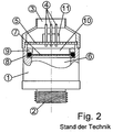
- FIG. 1 shows the simplified basic structure of a Mixed gas - Kreislaufatemauss according to the prior art Technology [1] [2] [3] [4].
- the device for mixing gas supply into the breathing circuit is mostly from an automatic valve for mixed gas (22), the one from a compressed gas tank originating and under one Medium pressure gas mixture (21) is supplied. Of the associated compressed gas tank and the pressure reducer are off For clarity, not shown.
- the gas mixture usually exists in the case of diving equipment one or more inert gases, such as helium or nitrogen, and a small proportion of oxygen which is such that even at the maximum depth of a physiological dangerous too high oxygen partial pressure does not occur can.
- inert gases such as helium or nitrogen
- oxygen which is such that even at the maximum depth of a physiological dangerous too high oxygen partial pressure does not occur can.
- mixed gas breathing apparatus for atmospheric conditions is used as a gas mixture ordinary largely dried and used oil-free compressed air.
- the automatic valve (22) is usually as lung automatic Valve designed via a diaphragm (24) is controlled.
- a relative negative pressure relative to the ambient pressure prevails, then presses the membrane (24) using a lever mechanism, a spring together and lifts the Valve from the valve seat, whereby the supplied to (21) Gas mixture at (23) flows into the mixing chamber (17).
- the spring pushes the diaphragm back to the starting position and the valve closes again. This will ensure that the user regardless of the degree of filling of the counterlung always a full Take a breath out of the device.
- diving equipment is Moreover, when diving always a relative negative pressure in the Breathing circuit avoided without the user has to intervene.
- the gas sensor (1) a Gas-sensitive front (2) has, at the one sensitive diffusion membrane is located (not shown), while its backside with the electrical connections (4) an opening (3) which may not be closed, because below the circuit board (5) sits one Pressure compensation diaphragm (7), which for the pressure equalization of Electrolyte chamber (6) is necessary.
- On the back Connection opening (3) of the gas sensor must be secured its correct function essentially the same pressure prevail as on its gas sensitive front (2).
- this pressure equalization obstructs, such as through watertight Potting the back of the sensors with a synthetic resin, then the pressure equalization of the electrolyte chamber takes place Deformation of the sensitive diffusion membrane at the gas-sensitive front, which directly leads to measurement errors and long term leads to failure of the gas sensor.
- the pressure compensation chamber (10) between the Circuit board (5) and the pressure compensation diaphragm (7) completely shed, as in the circuit board usually only there are a few small holes, mostly Through-holes of printed conductors, or bare Component positions that just barely for pressure equalization the pressure compensation chamber through a gaseous medium suffice.
- a leak passes the aggressive Electrolyte fluid to the circuit board and zerfrisst their Tracks and soldered electronic components. A sudden failure of the gas sensor is the result.
- the diving equipment according to [2] [3] try the solution of the Condensation problem thereby, by the soda lime around the Gas sensors is arranged around.
- the principle of action exists here in it, the exothermic reaction of soda lime to warm up the Gas sensors to be used, which are lapped by the breathing gas. By the warming will be below the dew point at the electrical and electronic components, including theirs Connecting cables, prevented.
- this working principle is not explicitly mentioned in [2] [3], though the whole peculiar design of the device is derived from it. Condensation at the critical parts is avoided as long as the soda lime has a sufficient temperature.
- Another well-known principle of action to ward off condensation in respiratory equipment is the gas intended for analysis in a drying device to dry before the des gas-sensitive sides of the gas sensors or another Analyzer is supplied.
- drying device An example of such a drying device is located in [9].
- this requires a significant Auxiliary energy for electric heating, what an autonomous Respiratory equipment is not practical.
- That of drying devices of this kind suggested prelude of a chemical drying agent in front of the gas-sensitive sides
- the gas sensors would also have the disadvantage that the Desiccant to a sufficient for the measurement Flow should be monitored, and that without further energy-consuming means - such as pumps - and hardly It would be possible, the analyzed respiratory gas the cycle again supply or expel it from the respirator, wherein the latter would also be a detrimental waste of breathing gas.
- the novel mode of action is based on the basic idea, in one Device for mixed gas supply in Kreislaufatemellan for Keep dry the electrical connection side of the gas sensors the mixed gas supplied from the automatic valve itself take advantage of this because of regulations be absolutely dry must be in order to avoid unwanted condensation in the Compressed gas tank and icing of the pressure reducer and the to avoid automatic valve.
- the drying of the Mixed gas takes place according to the known prior art regularly already in the compressor, the compressed gas tank filled.
- the used up Discharge breathing gas into the environment instead of preparing it causes the dry breathing gas regularly dryness in the Mouth of the user. Nevertheless, nobody seems to be up yet
- the idea came from this intrinsically annoying property of a respiratory automatic valve derived dry respiratory gas in an advantageous manner as a novel mode of action for Keep dry the connection side of the gas sensors in one Exploit recirculation breathing apparatus.
- This new mode of action can be used to keep dry electrical and electronic components of the respirator be extended.
- First pressure compensators are by the two tasks characterized, first, the excess part of the automatic valve derived dry mixed gas in the Derive breathing circuit, so that at the pressure equalization membranes the gas sensors to the breathing circuit no Overpressure arises, and secondly, moist breathing gas from the To prevent breathing circuit from being connected to the connection sides of the Gas sensors or the other dry-containing electrical and electronic components.
- First pressure compensating means are placed between the outlet of the automatic valve and the breathing circuit arranged.
- the first Pressure equalizing means a single directional valve.
- the breathing apparatus can also dry cartridges with a drying agent or a combination of at least a directional valve and a drying cartridge first Pressure compensation means are used.
- the use of a Drying agent is always optional, because the Device according to the invention can also without such get along.
- the device according to the invention succeeds for mixed gas supply in a surprisingly simple way, by Exploitation of the supplied from the automatic valve dry mixed gas condensation on the electrical connections and supply lines of the gas sensors or on other electrical or electronic components of the Respirator reliably prevent the interaction the automatic valve and the first pressure compensator always a perfect pressure equalization of the pressure compensation membrane the gas sensors ensured.
- the invention has compared with previous solutions [10] [11] the same inventor the additional advantage, without aggravation the field interchangeability of the gas sensors on a Desirable to completely dispense drying agent, or such at least so much to spare that it is much rarer has to be exchanged than with the previous solution [11].
- the invention has the Advantage, about a new mode of action to prevent the Condensation at the electrical connections of the gas sensors or to the other electrical or electronic Components of the breathing apparatus, its function proven at any time and also understood by lawyers can be, and that is why any suspicion as Potential cause of accident is sublime.
- the invention thus defuses the product liability problem significantly paves the way for a flourishal march of it equipped electronically controlled mixed gas recirculation dipping devices on the world market.
- FIG. 1 shows the simplified basic structure of a Mixed gas - Kreislaufatem advocatess according to the prior art Technology.
- FIG. 2 shows a commercially available gas sensor according to FIG known prior art, to explain its internal Components partly cut open.
- Figure 3 shows schematically the novel device for Mixed gas supply according to the main claim.
- Figure 4 shows schematically a further developed novel Apparatus for mixing gas supply.
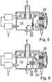
- Figure 5 shows schematically a novel device for Mixed gas supply, in which the first pressure equalizing agent Directional valve is.
- Figure 6 shows schematically a novel device for Mixed gas supply, in which the first pressure compensation means a Drying cartridge is.
- Figure 7 shows schematically a novel device for Mixed gas supply, in which the first pressure compensation means a Combination of a directional valve and a drying cartridge are.
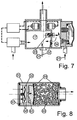
- FIG. 8 shows by way of example the internal structure of a Combination with a directional valve first Pressure equalizing agent particularly suitable drying cartridge, the itself contains another directional valve.
- Figure 9 shows an example of a longitudinal section through a Practical realization of the device according to the invention for Mixed gas supply in a rebreather, in which the Gas sensors in a particularly advantageous sensor unit are housed.
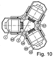
- Figure 10 shows a cross section through the Sehsortician the Figure 9, from which the position of the pressure equalization channels of Sensor unit is completely recognizable.
- a breathing circuit in which a breathing gas flow (29,30) flows, as well as an automatic valve for Mixed gas supply (22) and at least one gas sensor (1) with dry electric or electronic Components that are connected via its rear connection opening (3) are accessible.
- the automatic valve compensates for a negative pressure, it opens when the breathing apparatus has a relative negative pressure Balance is, and it closes when the Negative pressure is balanced.
- the invention is characterized in that in a Kreislaufatem réelle derived from the automatic valve dry mixed gas (23) is used to dry electrical or electronic components of the gas sensors.
- the simplest realization of the device according to the invention contains an antechamber (34) over the first Pressure equalizing means (31) with the breathing circuit (29, 30) so in Connection stands that the gas located in the antechamber through the first pressure equalizing means into the The breathing circuit can escape as soon as it enters the antechamber greater pressure prevails than in the breathing circuit.
- a smaller pressure prevail than in Breathing circuit then opens the automatic valve and it a pressure equalization takes place by the automatic from the Valve-derived dry mixed gas (23) in the antechamber flows.
- the first pressure equalizing means may be on the side of the Breathing circuit at any point connected to this become. You could, for example, also in the deformable Sack of counterlung flow. For the sake of robustness and the However, the best possible function of the mixing process are Prefer realizations, where the first Pressure equalization means the pressure equalization between the antechamber and a solid mixing chamber (17) effect.
- connection sides (3) of the gas sensors (1) stand with the antechamber (34) in connection, which am the simplest way can be realized that the Gas sensors are housed in a part of the antechamber, being screwed sealed in threaded holes, located in the wall between the mixing chamber and the antechamber are located.
- a sealant is an O-ring, the usually with standard gas sensors standard on the foot the thread on its gas-sensitive front (2) already is available.
- the gas-sensitive front pages (2) the gas sensors with the breathing gas flow (30) from the mixing chamber (17) directly related to what their function while their moisture sensitive ones are coming in Backs and their electrical leads in the dry prechamber (34) are located.
- flawless Solutions for watertight implementation of electrical Connecting cables through housing walls to the evaluation electronics have long been known in the art.
- the Evaluation electronics and the other electrical components can also be kept dry Pre-chamber will be accommodated if this is big enough is performed.
- First pressure compensation means can be realized as a Directional valve, a drying cartridge, or a combination of Directional valves and a drying cartridge. Furthermore any conceivable means is the first one Pressure compensation means, as long as the tasks of the first Pressure equalizing means, already shown above, can fulfill.
- Figure 4 shows schematically a further developed novel Apparatus for mixed gas supply, with said Accidents better cope, and in addition to a particularly advantageous realization of an optimal Temperature compensation of the gas sensors can achieve.
- the second Pressure equalizing means (36) connect the interior of the prechamber with the interior of the sensor chamber (s) and they allow one bidirectional pressure equalization of the sensor chamber (s) with the Antechamber, this pressure compensation process is in the figure with the Gasflußpfeilen by the second pressure equalizing agent clarified.
- Second pressure compensation means have the purpose of Connection sides of the gas sensors a more extensive protection against moisture or condensation in the case provide that an accident occurs in the device, the in particular the desired action of the first pressure compensation means diminished or abolished, so that contrary to the intentions of Invention yet humid breathing gas or even condensation from the breathing circuit back into the antechamber.
- Second pressure equalizing means useful for this purpose may be used.
- Possible realizations second Pressure compensation means are pressure equalization channels of small size Cross-section showing the gas exchange between the antechamber and the sensor chamber to the necessary pressure equalization measure restrict, or dry cartridges, a desiccant contain, or a combination of the said means.
- the Use of directional valves would be here as well conceivable, but seems to be rather an unnecessary complication.
- first pressure compensating means in connection with the device according to the invention in the manner of Figure 3 exemplified. It is understood that the hereby shown in the first pressure compensation means also in the further developed device used in the manner of Figure 4 can be.
- FIG 5 is the simplest possible example Realization of the first pressure compensation means (31) as Directional valve (32) illustrated.
- This directional valve allows it in the prechamber (34) located gas in the Mixing chamber (17) and thus to escape into the breathing circuit, if in the antechamber towards the breathing circuit relative overpressure prevails.
- a relative negative pressure in the Antechamber equalizes the automatic valve (22), as already was detailed above.
- Pressure compensation diaphragm is given by both commercial directional valves as well as commercially available automatic valves already at a few tens of millibar Can address pressure difference.
- Suitable as a directional valve so-called mushroom valves made of an elastomeric material, or any other suitable valve for this purpose.
- FIG. 6 shows by way of example a realization of the first embodiment Pressure compensation means (31), which also in the case of Exhaustion of the mixed gas supply pressure equalization of Prechamber and thus the gas sensors is always guaranteed, by the first pressure equalizing means (31) as a drying cartridge (33) is realized, in which there is a desiccant, that in the figure as small balls within the part cut dry cartridge is shown.
- the drying cartridge at Pressure compensation processes mostly from dry from the automatic valve (22) derived mixed gas (23) in the direction flows through the mixing chamber (17), and the drying agent is spared.
- Some types of drying agent are by them flowing dry mixed gas even regenerated something.
- the drying cartridge must be in this Case, however, have a relatively large cross-section.
- Diving equipment is not such a realization practicable because at great depths the breathing gas is a much larger Density than under atmospheric conditions.
- Respiratory equipment for atmospheric conditions has the realization according to Figure 6 but the advantage, without directional valves get along, which are known to be prone to failure than Dry cartridges. Such is for the latter application about as big as an ordinary gas mask filter.
- Figure 7 shows schematically and by way of example also for Diving apparatus suitable modification of the device of Figure 6.
- first pressure compensation means (31) realized by a combination of directional valves (32) and a Drying cartridge (33) containing a desiccant.
- an overpressure in the antechamber (34) can be in it located gas via the directional valve (32) in the Mixing chamber (17) and thus enter the breathing circuit.
- This gas flow symbolized by the lower arrow of (34)
- it is subject to only low resistance the directional valve.
- At a negative pressure in the antechamber can Breathing gas from the breathing circuit from the mixing chamber over the Dry cartridge with the desiccant in the Get to the antechamber. This gas flow is symbolized by the upper arrow, from (17) to (34).
- Negative pressure in the antechamber can with proper function of the automatic valve on not occur. However, this speaks too insensitive or delayed, or is the one supplied to (21) Mixture of gas completely exhausted, then provides the drying cartridge that, nevertheless, a pressure equalization takes place, and that the Gas sensors are not caused by too much negative pressure in the Damaged antechamber.
- FIG 8 shows an example of the cross section through a Drying cartridge (33), which has its own directional valve (32) contains.
- a drying cartridge in which the Desiccant is a directional valve upstream, is for a device according to Figure 7 particularly suitable, since the Desiccant is spared best possible.
- a convenient one Construction of such a drying cartridge from left to right, consists of a spring washer (57) having a valve cap (58) in the drying cartridge locked and against resilient curved Screen discs (59) presses on the desiccant (60) to hold his place.
- a gas-permeable filter material (61) provided, for example Cotton wool.
- Such a drying cartridge can with its thread, on right end recognizable, in a device in type of figure 7 in the partition between the mixing chamber (17) and the Prechamber (34) releasably and sealed attached.
- Sealant is an O-ring.
- the gas that flows through them contains water vapor remove moisture and bind it, For example, a silica gel in spherical shape.
- Figure 9 shows an example of a longitudinal section through a Practical realization of the further developed device for Mixed gas supply in an electronically controlled self-mixing rebreather whose sensor unit is in executed particularly advantageous manner, whereby at expedient arrangement of the sensor unit within the Respirator and when choosing a material with good Thermal conductivity is the best possible function of Temperature compensation of the gas sensors are ensured can. This succeeds especially when the sensor unit from Breathing gas flow is washed around.
- the exhaled breathing gas (28) from the exhalation tube (15), the connected to a nozzle of a central section (37), first in a circulating distribution chamber (38) and then About at the radius distributed bean in the absorber chamber (39).
- the Atemkalkpatrone (16) from the respiratory gas flow lapped and thus against the wall of the absorber chamber thermally insulated. Collecting at the bottom of the absorber chamber Condensation or by short-term loss of the mouthpiece Penetrated seawater can through a drain valve (51) off be expressed by the breathing apparatus by using a manual control knob (41) on the automatic valve (22) an overpressure is produced in the breathing apparatus.
- soda lime cartridges are not the object of this invention, but it should be noted that instead of the here shown symbolically and simplified axially flowed Atemkalkpatrone also a radial perfused soda lime cartridge can be used. In a such would be the feed holes then on the circumference and at the center of the cartridge would be one dürchlochtes central tube are located.
- the Gas sensors are mounted in a base body (44), wherein their gas-sensitive front sides (2) into a central bore (45) of the base body, and wherein the gas sensors (1) each in individual sensor chambers (35) sitting through the detachable connection of sensordomes (46) to the main body (44) are formed.
- This detachable connection can be a Be screwed.
- the gap between sensor dome and Body is sealed, for example with an O-ring.
- This produced a pressure equalization in the sensor chambers can be located in the body Pressure equalization channels (47), in the figure 8 due to the location the section only partially visible, with which the Sensor chambers are connected and by di e also the electrical leads of the gas sensors (25) are guided can.
- These pressure equalization channels in the main body of Sensor unit, described in more detail later in Figure 9 are about Supply pipes (48) connected to the pre-chamber (34). Then the pressure compensation channels and the supply pipes act as second pressure compensation means according to the characteristics of Invention, because they provide the pressure balance between the Prechamber and the sensor chamber ago.
- the antechamber is formed by a suitable sealed intermediate bottom (56) in the housing tube (54) of the Respirator is used.
- This intermediate floor separates the Prechamber (34) from the mixing chamber (17).
- Supply pipes (48) may not be stable enough to hold the Intermediate floor via the sensor unit with the middle section too can connect between the intermediate floor and the Middle section additional stable studs are provided. In general, however, such a measure is not necessary because the base body (44) and the sensor dome (46) of the sensor unit (43) and the supply pipes (48) preferably made of metal manufactured and therefore stable enough.
- the middle section preferably turns off made of a stable plastic, then no Cold bridge between the environment and the sensor unit.
- Another variant for the realization of the second Compression means would be that one of the Main body originating supply pipes in a drying cartridge opens that between the sensor chamber and the Prechamber during pressure equalization flowing gas in addition Dries while the other supply pipes, which then only to Guide the electrical leads used to the sensors be sealed with a sealant so that they themselves no longer act as second pressure equalizing agent.
- the first Pressure balance means a drying cartridge or a combination used from a drying cartridge and from directional valves is, because if a desiccant is already present and Maintenance costs brings, then is a second drying agent to further increase the moisture protection no substantial overhead.
- the first pressure equalizing means (31) but only as a Directional valve (32) realized.
- a completely exhausted Mixed gas supply would force to emergency rescue.
- During the emergency climb can but opposite in the antechamber only a relative overpressure is created in the breathing circuit, then via the directional valve in the breathing circuit escapes.
- the characteristics of the invention are thereby realized by the mixed gas (23) coming from the automatic valve (22) first enters the pre-chamber (34), which then happens if in the breathing apparatus relative to the environment a relative Negative pressure prevails, which opens the automatic valve.
- Out the antechamber reaches the incoming dry mixed gas (34) to the connection sides of the gas sensors and thus on their Pressure equalization membranes.
- second pressure equalizing means 36, 47, 48
- the Gas sensors are housed in individual sensor chambers (35).
- These sensor chambers are within one particular advantageous sensor unit (43) according to claim 11 characterized formed sensor dome (46) in a base body (44) of the Detachable sensor unit, which is a central bore (45), which flows through the respiratory gas to be analyzed becomes.
- the automatic valve derived mixed gas (23) via the first pressure equalizing agent (31), which is designed here as a directional valve (32), in the Mixing chamber (17) and thus supplied to the breathing circuit.
- the dry held pre-chamber contains in this practical Embodiment also the evaluation electronics (26) and the Dosing valve (19) for the oxygen. This allows the waiver on waterproof cable glands.
- the Dosing valve (19) passes the oxygen originating from it the mixing chamber (17), where it is located with the there Breathing gas mixes.
- the thus regenerated breathing gas (30) passes through the sensor unit through at the gas-sensitive sides of Gas sensors (2) over a pipe bend (49) and a Feedthrough tube (50) into the inhalation tube (13).
- the Passage tube pierces the used Exhaled gas leading circulating distribution chamber (38) and is sealed against this.
- the body of the Respiratory equipment consists of housing tubes (54) which are detachable, but sealed to the center section (37), wherein the ends of the device are closed with lids (55).
- the Device is by means of a running along the central axis Tie rod (52) held together at the top by means of a thread is screwed into the upper lid, and the at the lower end with a handwheel (53) is connected.
- Figure 10 shows a cross section through the particular advantageous sensor unit of Figure 9 in height of the central axis the gas sensors (1).
- the main body (44) of the sensor unit There is a central bore (54) through which the regenerated breathing gas flows and thus to the gas-sensitive Front sides (2) of the gas sensors arrives.
- the gas sensors are connected to the body releasably and sealed.
- sensor dome (46) also with the main body detachably and sealed connected to one for each gas sensor own sensor chamber (35) to form.
- pressure equalization channels (47) are present. These can be designed so that they are already within the Sensor unit the interior of the sensor chambers with each other connect. Such pressure equalization channels can than as from Sensor chambers leading holes of small cross-section, which in lead larger vertical holes in the body, executed become.
- the Inventive device for mixed gas supply in Circulatory breathing apparatus largely independent of the nature of the Respirator is very versatile and convertible. she can depend on the field of application and the specific Requirements of the respective breathing apparatus by a choice of more or less complex pressure compensation means in be optimally designed, resulting in a variety possible variants results in the context of the description not all can be listed, so the description in no way as an exhaustive treatise of all possible Variants is to be considered.
- the possible variants and conversions The invention is based solely on the claims of Invention.
- the valves, including the automatic valve in any convenient way will be realized.
- the automatic valve instead of a membrane also via a pressure sensor be electronically controlled.
- the directional valves can be spring-loaded discs made of a suitable material.
- First pressure compensation means can be on their the mixing chamber facing side a water-repellent, but gas-permeable Diaphragm of sufficient cross-section upstream to sloshing condensation that is in the breathing circuit can be located from the first pressure compensation means keep.
- the new device for mixed gas supply in Circulatory breathing apparatus achieved by inventive use the supplied dry mixed gas for keeping dry the electrical and electronic components of the gas sensors an improved over the prior art Drying effect and she is remarkably simple Working principle also understandable for lawyers and therefore about beyond doubt.
- the new device can optionally use dry cartridges use a desiccant, but then achieved against the previous solution [11] a much longer service life of Desiccant.
- Be the first pressure equalizing agent Directional valves are used together with a drying cartridge, so that the desiccant only in case of failure of the Pressure equalization of the pre-chamber via the automatic valve is flowed through, the desiccant is only in such Accidents consumed, and usually does not need more often be replaced as the gas sensors themselves, what about once Can be done during a routine maintenance in the year.
- the description also discloses a rebreather the inventive device for mixed gas supply in one Variant is used, which do without desiccant examined. This is based on the consideration that a failure of the Mixed gas supply the diver in any case to an immediate Ascension forces, leaving a vacuum in the antechamber as well no longer arises and therefore no longer about one Desiccant must be balanced.
- This Rebreather uses one for temperature compensation the gas sensors particularly advantageous Sensor unit in a total construction, in the dry cartridges if necessary, as first and second pressure compensation means could be retrofitted, which is another Advantage of this design is.
Landscapes
- Health & Medical Sciences (AREA)
- Pulmonology (AREA)
- General Health & Medical Sciences (AREA)
- Engineering & Computer Science (AREA)
- Mechanical Engineering (AREA)
- Ocean & Marine Engineering (AREA)
- Business, Economics & Management (AREA)
- Emergency Management (AREA)
- Emergency Medicine (AREA)
- Respiratory Apparatuses And Protective Means (AREA)
Abstract
Description
Eine derartige Realisierung der Erfindung, die ohne ein Trockenmittel auskommt, wird später noch beschrieben werden.
- 1
- Gassensor (meist Sauerstoffsensor)
- 2
- gasempfindliche Vorderseite des Gassensors
- 3
- rückseitige Anschlussöffnung des Gassensors
- 4
- elektrische Anschlüsse des Gassensors
- 5
- Leiterplatte
- 6
- Elektrolytkammer
- 7
- Druckausgleichsmembrane
- 8
- Dichtung der Druckausgleichsmembrane
- 9
- eingepresster Metallring
- 10
- Druckausgleichskammer des Gassensors
- 11
- Steckverbinder
- 12
- Gegenlunge
- 13
- Einatemschlauch
- 14
- Mundstückeinheit
- 15
- Ausatemschlauch
- 16
- Atemkalkpatrone
- 17
- Mischkammer
- 18
- Mitteldruck - Sauerstoff
- 19
- Dosierventil für Sauerstoff
- 20
- aus dem Dosierventil stammender Sauerstoff
- 21
- Mitteldruck - Mischgas
- 22
- automatisches Ventil für Mischgas
- 23
- aus dem automatischen Ventil stammendes Mischgas
- 24
- Membrane des automatischen Ventils
- 25
- elektrische Leitungen der Sauerstoffsensoren
- 26
- Auswertungselektronik
- 27
- elektrische Steuerleitung des Dosierventils
- 28
- ausgeatmetes Atemgas
- 29
- aus der Atemkalkpatrone stammendes Atemgas (weitgehend kohlendioxidbefreit)
- 30
- regeneriertes Atemgas
- 31
- erstes Druckausgleichsmittel (zwischen Vorkammer und Mischkammer)
- 32
- Richtungsventil
- 33
- Trockenpatrone
- 34
- Vorkammer
- 35
- Sensorkammer
- 36
- zweites Druckausgleichsmittel (zwischen Vorkammer und Sensorkammer)
- 37
- Mittelsektion
- 38
- umlaufende Verteilungskammer
- 39
- Absorberkammer
- 40
- wasserabweisende, gasdurchlässige Membrane
- 41
- Betätigungsknopf für automatisches Ventil
- 42
- zentrale Kammer
- 43
- Sensoreinheit
- 44
- Grundkörper der Sensoreinheit
- 45
- Zentralbohrung des Grundkörpers
- 46
- Sensordom
- 47
- Druckausgleichskanäle (im Grundkörper der Sensoreinheit)
- 48
- Zuleitungsrohr
- 49
- Rohrkrümmer
- 50
- Durchführungsrohr (durchstößt 38)
- 51
- Ablassventil
- 52
- Zugstange
- 53
- Handrad
- 54
- Gehäuserohr
- 55
- Deckel
- 56
- Zwischenboden
- 57
- Federring
- 58
- Ventilkapsel
- 59
- Siebscheibe
- 60
- Trocknungsmittel
- 61
- gasdurchlässiges Filtermaterial
Claims (11)
- Vorrichtung zur Mischgaszufuhr in Kreislaufatemgeräten, bestehend ausdadurch gekennzeichnet,einem Atemkreislauf, in dem ein Atemgasstrom (29, 30) fließt,einem automatischen Ventil (22) zur Mischgaszufuhr aus einem Druckgasvorrat (21),mindestens einem Gassensor (1) mit elektrischen oder elektronischen Komponenten (4, 5, 11), wobei gilt,dass das automatische Ventil öffnet, wenn im Atemgerät ein Unterdruck auszugleichen ist,dass das automatische Ventil wieder schließt, wenn der Unterdruck ausgeglichen ist,dass das aus dem automatischen Ventil stammende trockene Mischgas (23) dazu benutzt wird, um elektrische oder elektronische Komponenten (4, 5, 11) der Gassensoren (1) trockenzuhalten.
- Vorrichtung nach Anspruch 1,
dadurch gekennzeichnet,dass das aus dem automatischen Ventil (22) stammende trockene Mischgas (23) nicht unmittelbar, sondern über erste Druckausgleichsmittel (31) in den Atemkreislauf gelangt,dass ein Teil des aus dem automatischen Ventil stammenden Mischgases vor ersten Druckausgleichsmitteln abgezweigt und den trockenzuhaltenden elektrischen oder elektronischen Komponenten (4, 5, 11) der Gassensoren (1) zugeführt wird. - Vorrichtung nach Anspruch 2,
dadurch gekennzeichnet,dass die ersten Druckausgleichsmittel im Falle eines relativen Unterdrucks in der Vorkammer gegenüber dem Atemkreislauf kein feuchtes Atemgas aus dem Atemkreislauf zurück in die Vorkammer gelangen lassen.dass das aus dem automatischen Ventil (22) stammende trockene Mischgas (23) in eine Vorkammer (34) gelangt,dass die Vorkammer gegenüber dem Atemkreislauf (29, 30) weitgehend abgedichtet ist,dass die trockenzuhaltenden elektrischen oder elektronischen Komponenten (4, 5, 11) der Gassensoren (1) mit der Vorkammer in Verbindung stehen,dass die Vorkammer über erste Druckausgleichsmittel (31) mit dem Atemkreislauf verbunden ist, wobei gilt,dass die ersten Druckausgleichsmittel einen relativen Überdruck in der Vorkammer gegenüber dem Atemkreislauf in den Atemkreislauf ableiten, - Vorrichtung nach Anspruch 3,
dadurch gekennzeichnet,dass die trockenzuhaltenden elektrischen oder elektronischen Komponenten (4, 5, 11) der Gassensoren (1) sich in einer Sensorkammer (35) befinden,dass die Sensorkammer gegenüber dem Atemkreislauf (29, 30) und gegenüber der Vorkammer (34) weitgehend abgedichtet ist,dass die Sensorkammer über zweite Druckausgleichsmittel (36) mit der Vorkammer verbunden ist, wodurch die trockenzuhaltenden elektrischen oder elektronischen Komponenten der Gassensoren mit der Vorkammer in Verbindung stehen,dass die zweiten Druckausgleichsmittel einen Druckausgleich zwischen der Sensorkammer und der Vorkammer bewirken. - Vorrichtung nach Anspruch 4,
dadurch gekennzeichnet, dass als ein zweites Druckausgleichsmittel (36) ein Druckausgleichskanal (47, 48) benutzt wird, der den Gasaustausch zwischen der Vorkammer (34) und der Sensorkammer (35) auf das zum Druckausgleich nötige Maß beschränkt. - Vorrichtung nach Anspruch 4,
dadurch gekennzeichnet, dass als ein zweites Druckausgleichsmittel (36) eine mit einem Trocknungsmittel gefüllte Trockenpatrone benutzt wird. - Vorrichtung nach einem der Ansprüche 3 bis 6,
dadurch gekennzeichnet, dass als ein erstes Druckausgleichsmittel (31) ein Richtungsventil (32) benutzt wird, welches einen Gasfluß von der Vorkammer (34) in den Atemkreislauf (29, 30) erlaubt, indem es sich öffnet, und welches einen Gasfluß vom Atemkreislauf in die Vorkammer verhindert, indem es sich schließt. - Vorrichtung nach einem der Ansprüche 3 bis 6,
dadurch gekennzeichnet, dass als ein erstes Druckausgleichsmittel (31) eine mit einem Trocknungsmittel gefüllte Trockenpatrone (33) benutzt wird, welche in beide Richtungen einen durch das Trocknungsmittel führenden Gasfluß zuläßt, und dabei einem vom Atemkreislauf (29, 30) in die Vorkammer (34) strömenden feuchten Atemgas genug Feuchtigkeit entzieht, so dass aus dem Atemkreislauf kein feuchtes Atemgas in die Vorkammer gelangt, sondern nur ein weitgehend getrocknetes Atemgas. - Vorrichtung nach einem der Ansprüche 3 bis 6,
dadurch gekennzeichnet, dass als ein erstes Druckausgleichsmittel (31) eine mit einem Trocknungsmittel (60) gefüllte Trockenpatrone (33) benutzt wird, welche ein Richtungsventil (32) enthält, das durch das Trocknungsmittel nur einen vom Atemkreislauf (29, 30) in die Vorkammer (34) führenden Gasfluß zuläßt, wobei das Trocknungsmittel dem durchströmenden feuchten Atemgas genug Feuchtigkeit entzieht, so dass aus dem Atemkreislauf kein feuchtes Atemgas in die Vorkammer gelangt, sondern nur ein weitgehend getrocknetes Atemgas. - Vorrichtung nach einem der obigen Ansprüche,
dadurch gekennzeichnet, dass sie eine Sensoreinheit enthält, in der mindestens eine Sensorkammer gebildet ist, wobei die Sensoreinheit aus einem wärmeleitenden Material gefertigt ist, und vom Atemgasstrom des Atemkreislaufs so umspült wird, dass sich ein guter Wärmeaustausch zwischen dem Inneren einer Sensorkammer und dem Atemgasstrom ergibt. - Vorrichtung nach Anspruch 10,
dadurch gekennzeichnet,dass der Grundkörper (44) der Sensoreinheit eine Zentralbohrung (54) aufweist,dass die Gassensoren (1) mit dem Grundkörper lösbar verbunden sind, sodass die gasempfindliche Vorderseite (2) der Gassensoren in die Zentralbohrung weisen,dass Sensorkammern (34) gebildet sind, indem Sensordome (46) über den Gassensoren mit dem Grundkörper lösbar verbunden sind,dass im Grundkörper Druckausgleichskanäle (47) vorhanden sind,dass diese Druckausgleichskanäle Teil des zweiten Druckausgleichsmittels der Vorrichtung sind.
Applications Claiming Priority (2)
| Application Number | Priority Date | Filing Date | Title |
|---|---|---|---|
| DE102004002034 | 2004-01-14 | ||
| DE102004002034A DE102004002034A1 (de) | 2004-01-14 | 2004-01-14 | Vorrichtung zur Mischgaszufuhr in Kreislaufatemgeräten |
Publications (2)
| Publication Number | Publication Date |
|---|---|
| EP1555043A2 true EP1555043A2 (de) | 2005-07-20 |
| EP1555043A3 EP1555043A3 (de) | 2007-08-01 |
Family
ID=34609554
Family Applications (1)
| Application Number | Title | Priority Date | Filing Date |
|---|---|---|---|
| EP05000657A Withdrawn EP1555043A3 (de) | 2004-01-14 | 2005-01-14 | Vorrichtung zur Mischgaszufuhr in Kreislaufatemgeräten |
Country Status (2)
| Country | Link |
|---|---|
| EP (1) | EP1555043A3 (de) |
| DE (1) | DE102004002034A1 (de) |
Cited By (2)
| Publication number | Priority date | Publication date | Assignee | Title |
|---|---|---|---|---|
| CN112243940A (zh) * | 2020-01-15 | 2021-01-22 | 江门市埃尔特机械设备有限公司 | 一种渔业养殖用增氧机 |
| EP3895977A4 (de) * | 2018-12-14 | 2022-09-28 | "Aquabreather" LLC | Rebreather mit einzelnem geschlossenem kreislauf zum unterwassertauchen |
Families Citing this family (3)
| Publication number | Priority date | Publication date | Assignee | Title |
|---|---|---|---|---|
| DE202009018003U1 (de) | 2009-04-20 | 2010-12-23 | Tauchtechnik Schmitt Gmbh | Vorrichtung zur Mischung von Gasen |
| DE102015219569B4 (de) * | 2015-10-09 | 2024-05-16 | Vitesco Technologies Germany Gmbh | Elektronische Anordnung, Kombination und Verfahren zur Montage einer elektronischen Anordnung |
| DE102015219571A1 (de) * | 2015-10-09 | 2017-04-13 | Conti Temic Microelectronic Gmbh | Sensordom-Anordnung |
Citations (8)
| Publication number | Priority date | Publication date | Assignee | Title |
|---|---|---|---|---|
| US3556098A (en) | 1968-12-04 | 1971-01-19 | John W Kanwisher | Apparatus for controlling environmental conditions, suitable for use underwater |
| DE2104153A1 (de) | 1971-01-29 | 1972-08-24 | Drägerwerk AG, 2400 Lübeck | Tauchgerät mit Kreislauf |
| US3710553A (en) | 1970-01-28 | 1973-01-16 | Biomarine Industries | Carbon dioxide scrubber and breathing diaphragm assembly for diving apparatus |
| EP0819936A1 (de) | 1996-07-19 | 1998-01-21 | Teledyne Industries Inc. | Ein verbesserter temperaturausgegliechener elektrochemischer Sensor und Verfahren zur genauen Überwachung von Temperaturänderungen eines zu untersuchenden Gases |
| WO1999007442A2 (en) | 1997-08-10 | 1999-02-18 | Wible Dan S | Diving system with interchangeable gas packs |
| WO1999013944A1 (en) | 1997-09-18 | 1999-03-25 | A P Valves | Self-contained breathing apparatus |
| DE3790537C2 (de) | 1986-09-19 | 2002-06-13 | Perma Pure Inc | Fluidtrocknungsvorrichtung |
| DE10328356A1 (de) | 2003-06-24 | 2005-01-13 | Bernhard Engl | Vergiessbarer Gassensor und Vergussverfahren dafür |
Family Cites Families (1)
| Publication number | Priority date | Publication date | Assignee | Title |
|---|---|---|---|---|
| AU2002222831A1 (en) * | 2000-10-31 | 2002-05-15 | Marat Vadimovich Evtukhov | Integral life support system |
-
2004
- 2004-01-14 DE DE102004002034A patent/DE102004002034A1/de not_active Withdrawn
-
2005
- 2005-01-14 EP EP05000657A patent/EP1555043A3/de not_active Withdrawn
Patent Citations (8)
| Publication number | Priority date | Publication date | Assignee | Title |
|---|---|---|---|---|
| US3556098A (en) | 1968-12-04 | 1971-01-19 | John W Kanwisher | Apparatus for controlling environmental conditions, suitable for use underwater |
| US3710553A (en) | 1970-01-28 | 1973-01-16 | Biomarine Industries | Carbon dioxide scrubber and breathing diaphragm assembly for diving apparatus |
| DE2104153A1 (de) | 1971-01-29 | 1972-08-24 | Drägerwerk AG, 2400 Lübeck | Tauchgerät mit Kreislauf |
| DE3790537C2 (de) | 1986-09-19 | 2002-06-13 | Perma Pure Inc | Fluidtrocknungsvorrichtung |
| EP0819936A1 (de) | 1996-07-19 | 1998-01-21 | Teledyne Industries Inc. | Ein verbesserter temperaturausgegliechener elektrochemischer Sensor und Verfahren zur genauen Überwachung von Temperaturänderungen eines zu untersuchenden Gases |
| WO1999007442A2 (en) | 1997-08-10 | 1999-02-18 | Wible Dan S | Diving system with interchangeable gas packs |
| WO1999013944A1 (en) | 1997-09-18 | 1999-03-25 | A P Valves | Self-contained breathing apparatus |
| DE10328356A1 (de) | 2003-06-24 | 2005-01-13 | Bernhard Engl | Vergiessbarer Gassensor und Vergussverfahren dafür |
Cited By (4)
| Publication number | Priority date | Publication date | Assignee | Title |
|---|---|---|---|---|
| EP3895977A4 (de) * | 2018-12-14 | 2022-09-28 | "Aquabreather" LLC | Rebreather mit einzelnem geschlossenem kreislauf zum unterwassertauchen |
| IL282974B1 (en) * | 2018-12-14 | 2025-03-01 | Aquabreather Llc | Individual closed-circuit rebreather for underwater diving |
| IL282974B2 (en) * | 2018-12-14 | 2025-07-01 | Aquabreather Llc | Individual closed-circuit rebreather for underwater diving |
| CN112243940A (zh) * | 2020-01-15 | 2021-01-22 | 江门市埃尔特机械设备有限公司 | 一种渔业养殖用增氧机 |
Also Published As
| Publication number | Publication date |
|---|---|
| EP1555043A3 (de) | 2007-08-01 |
| DE102004002034A1 (de) | 2005-08-11 |
Similar Documents
| Publication | Publication Date | Title |
|---|---|---|
| DE2907416C2 (de) | ||
| DE3015584C2 (de) | Druckgasbelüfteter Schutzanzug mit Atemschutzgerät | |
| DE3230939C2 (de) | Atemschutzmaske mit Innenhalbmaske | |
| DE3742639C2 (de) | Atemgerät mit geschlossenem Kreislauf | |
| DE69211996T2 (de) | Autonomes notatemschutzgerät | |
| DE2817561A1 (de) | Tragbares atemgeraet (sauerstoffgeraet) | |
| DE3015760A1 (de) | Lungengesteuertes druckgas-atemschutzgeraet mit ueberdruck in der atemschutzmaske | |
| DE3874258T2 (de) | Ausatmungsventil mit abgleich fuer atemgeraete mit geschlossenem kreislauf. | |
| DE69702964T2 (de) | Zuführleitung für eine beatmungsausrüstung | |
| DE2111241C3 (de) | Atmungsgerät mit einer Maske | |
| DE2811993A1 (de) | Atmungsventil fuer rettungsapparat | |
| EP1555043A2 (de) | Vorrichtung zur Mischgaszufuhr in Kreislaufatemgeräten | |
| DE202015106233U1 (de) | Vorrichtung zur Umschaltung eines Rebreathers vom geschlossenen in den offenen Atemmodus | |
| DE2919492A1 (de) | Unabhaengige, lebenserhaltende notvorrichtung zur aufnahme von tauchern und verfahren zum lebenserhalten von tauchern | |
| AT513590A1 (de) | Verfahren zur Verlängerung der Einsatzdauer eines umluftunabhängigen Druckluft-Atemgeräts | |
| DE1142677B (de) | Vorrichtung zur Bemessung des Narkosemittels im Narkosegas eines Narkoserueckatmungs-systems | |
| DE2230602C3 (de) | Atmungsgerät für Taucher | |
| DE3829115A1 (de) | Atemgeraet | |
| DE3315070C2 (de) | Notatemgerät | |
| EP0155991A1 (de) | Kohlenoxid-Atemschutzgerät | |
| DE10259988B3 (de) | Gassensorvorrichtung für Atemgeräte | |
| DE3005980C2 (de) | Atemschutzanzug mit Anzeigeeinrichtung für den Atemgasvorrat | |
| DE10159219B4 (de) | Atemschutzmaske für einen Preßluftatmer | |
| AT507418B1 (de) | Gasverteilereinheit | |
| DE1155357B (de) | Atmungsgeraet fuer das Tauchen in groessere Tiefen |
Legal Events
| Date | Code | Title | Description |
|---|---|---|---|
| PUAI | Public reference made under article 153(3) epc to a published international application that has entered the european phase |
Free format text: ORIGINAL CODE: 0009012 |
|
| AK | Designated contracting states |
Kind code of ref document: A2 Designated state(s): AT BE BG CH CY CZ DE DK EE ES FI FR GB GR HU IE IS IT LI LT LU MC NL PL PT RO SE SI SK TR |
|
| AX | Request for extension of the european patent |
Extension state: AL BA HR LV MK YU |
|
| PUAL | Search report despatched |
Free format text: ORIGINAL CODE: 0009013 |
|
| AK | Designated contracting states |
Kind code of ref document: A3 Designated state(s): AT BE BG CH CY CZ DE DK EE ES FI FR GB GR HU IE IS IT LI LT LU MC NL PL PT RO SE SI SK TR |
|
| AX | Request for extension of the european patent |
Extension state: AL BA HR LV MK YU |
|
| AKX | Designation fees paid | ||
| STAA | Information on the status of an ep patent application or granted ep patent |
Free format text: STATUS: THE APPLICATION IS DEEMED TO BE WITHDRAWN |
|
| 18D | Application deemed to be withdrawn |
Effective date: 20080202 |
|
| REG | Reference to a national code |
Ref country code: DE Ref legal event code: 8566 |