EP1555067A2 - Pipette avec raccord pivotable - Google Patents
Pipette avec raccord pivotable Download PDFInfo
- Publication number
- EP1555067A2 EP1555067A2 EP05250194A EP05250194A EP1555067A2 EP 1555067 A2 EP1555067 A2 EP 1555067A2 EP 05250194 A EP05250194 A EP 05250194A EP 05250194 A EP05250194 A EP 05250194A EP 1555067 A2 EP1555067 A2 EP 1555067A2
- Authority
- EP
- European Patent Office
- Prior art keywords
- pipette
- pivot
- housing
- nozzle assembly
- nozzle
- Prior art date
- Legal status (The legal status is an assumption and is not a legal conclusion. Google has not performed a legal analysis and makes no representation as to the accuracy of the status listed.)
- Withdrawn
Links
Images


Classifications
-
- B—PERFORMING OPERATIONS; TRANSPORTING
- B01—PHYSICAL OR CHEMICAL PROCESSES OR APPARATUS IN GENERAL
- B01L—CHEMICAL OR PHYSICAL LABORATORY APPARATUS FOR GENERAL USE
- B01L3/00—Containers or dishes for laboratory use, e.g. laboratory glassware; Droppers
- B01L3/02—Burettes; Pipettes
- B01L3/021—Pipettes, i.e. with only one conduit for withdrawing and redistributing liquids
- B01L3/0213—Accessories for glass pipettes; Gun-type pipettes, e.g. safety devices, pumps
-
- B—PERFORMING OPERATIONS; TRANSPORTING
- B01—PHYSICAL OR CHEMICAL PROCESSES OR APPARATUS IN GENERAL
- B01L—CHEMICAL OR PHYSICAL LABORATORY APPARATUS FOR GENERAL USE
- B01L2200/00—Solutions for specific problems relating to chemical or physical laboratory apparatus
- B01L2200/08—Ergonomic or safety aspects of handling devices
- B01L2200/087—Ergonomic aspects
-
- B—PERFORMING OPERATIONS; TRANSPORTING
- B01—PHYSICAL OR CHEMICAL PROCESSES OR APPARATUS IN GENERAL
- B01L—CHEMICAL OR PHYSICAL LABORATORY APPARATUS FOR GENERAL USE
- B01L2400/00—Moving or stopping fluids
- B01L2400/04—Moving fluids with specific forces or mechanical means
- B01L2400/0475—Moving fluids with specific forces or mechanical means specific mechanical means and fluid pressure
- B01L2400/0487—Moving fluids with specific forces or mechanical means specific mechanical means and fluid pressure fluid pressure, pneumatics
-
- B—PERFORMING OPERATIONS; TRANSPORTING
- B01—PHYSICAL OR CHEMICAL PROCESSES OR APPARATUS IN GENERAL
- B01L—CHEMICAL OR PHYSICAL LABORATORY APPARATUS FOR GENERAL USE
- B01L2400/00—Moving or stopping fluids
- B01L2400/06—Valves, specific forms thereof
- B01L2400/0633—Valves, specific forms thereof with moving parts
Definitions
- This invention pertains generally to a laboratory device. More particularly, this invention pertains to an adjustable pipette device for aspirating and dispensing liquids.
- Pipetting is the act of aspirating and dispensing controlled volumes of liquid, and is one of the most frequently performed repetitive lab operations. Attempts to minimize the occurrences of RSIs in the lab have focused on training technicians in body mechanics (e.g., posture, pipetting technique, etc.), and providing a ergonomic pipette device.
- a pipette device is as important as the manner in which it is used.
- Pipette manufacturers recognize the benefits of an ergonomic pipette device, as is evidenced by the number of different ergonomic devices available.
- many devices include a contoured handgrip to allow for a relaxed hold on the device.
- a contoured handgrip is not sufficient to completely obviate the development of a RSI or CTD in awkward, confined or restricted spaces, such as pipetting at lowered benchtops or in fume hoods where arm, joint or tendon strain may occur. Healthy technicians will not only have better attendance and attitude, but will also perform better with improved pipetting accuracy and precision. Therefore, in view of the foregoing, a need exists for an adjustable ergonomic pipette device.
- the invention provides a pipette device with a pivotable nozzle assembly.
- the pipette device includes a housing defining a device axis.
- the nozzle assembly includes a pivot mechanism that is rotatably engaged with the device housing.
- the pivot mechanism includes pivot bosses and an indexing portion.
- a nozzle release is retained by a portion of the device housing, and is operative to engage and disengage the indexing portion to select the pivot angle of the nozzle assembly.
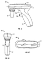
- FIG. 1A shows a side elevation view of the inventive pipette device.
- FIG. 1B shows a front elevation view of the device of FIG. 1A.
- FIG. 1C shows a top view of the device of FIG. 1A.
- FIG. 2 shows an exploded view of the device of FIG. 1A.
- FIG. 3A shows a perspective view of the pivot mechanism shown in FIG. 2.
- FIG. 3B shows a top view of the pivot mechanism shown in FIG. 3A.
- FIG. 4A shows a side elevation view of the nozzle release shown in FIG. 2.
- FIG. 4B shows a perspective view of the nozzle release of FIG. 4A.
- the illustrated embodiment of the pipette device 10 includes a generally pistol-shaped housing, although other shapes are suitable for the housing.
- the housing may be constructed of any suitable material known in the art, but preferably the housing is constructed of a plastic material molded or otherwise formed into two distinct halves 24a and 24b which are secured by fasteners such as screws 26 (FIG. 2).
- the housing includes an external matte finish that provides a non-slip surface for improved gripping and handling of the device 10.
- the housing includes a handgrip portion 12, a barrel portion 14, and a nozzle assembly 16.
- the barrel portion 14 is oriented substantially parallel with a horizontal work surface (e.g., table, benchtop, etc.) In this way, a device axis 11 is defined through the device 10, which is generally horizontal during typical use, but may oriented otherwise for the user's comfort.
- the nozzle assembly 16 is operable to releasably retain glass and plastic pipettes of various sizes and volumes. Additionally, as discussed in further detail below, the nozzle assembly 16 may be pivoted away from the handgrip portion 12 to reduce arm strain during pipetting.
- the handgrip portion 12 includes an ergonomic treatment to reduce hand strain and is hand-neutral (i.e., usable by both right-handed and left-handed users).
- Trigger buttons 18a and 18b are generally cylindrical and project through a portion of the handgrip portion 12.
- the buttons 18a, 18b are positioned for actuation by the user's fingers and may include an ergonomic treatment such as a curved, concave, or contoured end surface for reducing finger fatigue.
- the aforementioned end surface may include a button-identifying portion such as an indent or protrusion that provides a user with a means for telling the buttons apart.
- Buttons 18a and 18b activate the device 10 to aspirate and dispense fluid respectively as is common in the art, however the buttons 18a and 18b may alternatively dispense and aspirate fluid respectively. Referring now to FIG.
- buttons 18a, 18b actuate microswitches or the like (not shown) on the circuit board 44 to operate a reversible motorized pump mechanism 42, such as a vacuum pump or the like.
- the pump mechanism 42 applies a positive or negative pressure to an attached pipette via one of the variable valve assemblies 46 and connective flexible tubing (not shown) within the housing.
- a variable switch 22 is retained by a portion of the barrel portion 14 and may be linked to the circuit board 44 to select the speed of the pump mechanism 42 depending on the user's desired pipetting speed and precision.
- the pump mechanism 42 is energized by one or more batteries 48, which are rechargeably linked to a power jack 50.
- the nozzle assembly 16 includes a nozzle housing 28 with a generally frustoconical shape and central bore therethrough.
- the exterior of the nozzle housing 28 may include gripping detents 29 that facilitate disassembly of the nozzle assembly 16 for filter replacement, cleaning, autoclaving, or the like.
- gripping detents 29 that facilitate disassembly of the nozzle assembly 16 for filter replacement, cleaning, autoclaving, or the like.
- a number of elements are engaged within the nozzle housing 28.
- a pipette coupling 30 Disposed within the nozzle housing 28 is a pipette coupling 30 that is made of a rubber or other elastomeric material for frictionally engaging pipettes of various sizes and volumes.
- a filter 32 for preventing aspirated fluids from entering the pump mechanism 42.
- a seal 34 is engaged to the upper connector of the filter 32, and is sized and shaped to plug the pivot mechanism 38 central bore 55 (FIG. 3A, 3B).
- a tube fitting 40 to which the connective flexible tubing attaches is inserted into the central bore 55 and is held captive therein by the seal 34.
- a nozzle shield 36 is affixed to the pivot mechanism 38 and is generally annular in shape. The nozzle shield 36 is sized and shaped to substantially encompass the sides of the pivot mechanism 38, yet permits access to the bottom engagement portion of the pivot mechanism 38. In this manner, the nozzle housing 28 may be affixed to the pivot mechanism 38, thereby sealing the nozzle assembly 16.
- the pivot mechanism 38 is somewhat cylindrical in shape and includes a central bore 55 therethrough defining a pipetting axis.
- a first portion of the pivot mechanism 38 includes threads 56 that engage complementary internal threads of the nozzle housing 28.
- a second portion of the pivot mechanism 38 includes two diametrically opposed pivot bosses 54.
- the pivot bosses 54 are sized and shaped to snugly fit within pivot sleeves 52 on housing halves 24a and 24b. Additionally, o-rings or the like may be disposed on the pivot bosses 54 to provide for smooth rotation of the bosses 54 in sleeves 52.
- the pivot bosses 54 project outwardly from an integral support structure 57 and define a pivot axis 53 about which the pivot mechanism 38 rotates and transverse to the device axis 11 (FIG. 1A).
- the bosses 54 may be cylindrically, frustoconically, or otherwise shaped to permit rotation, but it is preferred that the bosses 54 be frustoconically shaped to provide a more tolerant fit in the pivot sleeves 52 so that wobble of the nozzle assembly 16 relative to the barrel portion 14 is minimized.
- the sleeves 52 and the bosses 54 are rotatably engaged and provide a pivoting means to angle or otherwise adjustably rotate an attached pipette about the pivot axis.
- the pivot mechanism 38 and pivot sleeves 52 may be arranged alternatively so the axes 11, 53 are oriented parallel, obliquely, or otherwise to achieve a desired pivoting of the nozzle assembly 16.
- the device 10 may alternatively include, for example, a swivel, ball, joint, articulation, ball-in-socket, or other like means for providing continuous adjustability in a variety of directions of the nozzle assembly 16.
- the device 10 may include a locking means to lock, clamp, or otherwise inhibit adjustment of the swivel, ball, joint, articulation, ball-in-socket or the like so the nozzle assembly 16 may be fixedly retained in a desired position.
- the locking means may include, for example, a pin, screw, clamp, vise, or other fastening means known in the art.
- indexing surface 58 Integral with the support structure 57 and spaced radially outwardly from the pivot bosses 54 is an indexing surface 58.
- the indexing surface 58 is slightly concave and includes a plurality of indexing holes. As shown, the indexing holes are arranged as three pairs of vertically spaced holes (59a, 59b, 59c), and the holes of each pair are horizontally and equally spaced apart a predetermined distance.
- the holes 59a, 59b, 59c when engaged by a retaining member such as the nozzle release 20 of FIGs. 4A and 4B, are operative to retain the nozzle assembly 16 at predetermined angles relative to the device axis 11.
- the bottom pair of holes 59a may orient the nozzle assembly 16 substantially perpendicular to the horizontal axis 11
- the middle pair of holes 59b may orient the nozzle assembly 16 at a first outward pivot angle (i.e., away from the handgrip portion 12)
- the upper pair of holes 59c may orient the nozzle assembly 16 at a second (and greater) outward pivot angle.
- the indexing surface 58 may be bisected by a channel 65, and the side portions of the support structure 57 proximate the indexing surface 58 may include indexing indents (67a, 67b, 67c). Inwardly projecting posts 66 within the housing halves 24a and 24b (FIG.
- the posts 66 mate with the indexing indents 67a, 67b, 67c to provide the user with an indication that the nozzle assembly 16 is adjustably retained at one of the predetermined angles.
- the posts 66 compress the halves of the bisected indexing surface 58 together.
- the posts 66 plunge into a pair of indexing indents 67a, 67b, 67c making an audible and sensory "pop", and allow the halves of the bisected indexing surface 58 to decompress.
- three pairs of holes and indents are illustrated, fewer or additional pairs could be included to provide a user with fewer or additional orientations of the nozzle assembly 16.
- the nozzle release 20 is slideably retained by a portion of the barrel 14, and is operable to select the pivot angle of the nozzle assembly 16.
- the nozzle release 20 is normally biased to engage the indexing holes 59a, 59b, 59c, thereby preventing accidental or undesired pivoting of the nozzle assembly 16 during pipetting.
- the nozzle release 20 includes a generally planar portion 60 with an upper side 60a and lower side 60b.
- An actuation projection 61 extends from the upper side 60a to facilitate sliding of the release 20 by a user's thumb or finger.
- a combination biasing and engagement portion 63 extends from the lower side 60b and includes a spring boss 62 and indexing nubs 64.
- the spring boss 62 extends rearward (toward the handgrip portion 12) and accepts a spring such as compression spring 21 as shown in FIG. 2.
- the release 20 is retained within an opening 19 in the housing proximate to an internal wall 51 (FIG. 2).
- the spring 21 is normally compressed against the wall 51 so that the spring force normally biases the release 20 forward (toward the nozzle assembly 16) in the opening 19.
- the indexing nubs 64 project into and releasably engage the indexing holes 59a, 59b, 59c.
- the indexing nubs 64 and holes 59a, 59b, 59c provide an indexing means for effecting discrete adjustment of the pivot angle of the nozzle assembly 16 and a pipette when attached thereto.
- a user may grasp the device 10 in one hand and slideably retract the release 20. With the other hand, the user may grasp the nozzle assembly 16 and pivot it to a desired orientation.
- the nubs 64 of the release 20 positively engage a pair of holes 59a, 59b, 59c, the release 20 may spring back to its normal position in the opening 19 as the user lets go of the release 20.
- the release 20 will remain displaced from its normal position in the opening 19, thereby providing the user with an indication of disengagement.
- the user may positively align the nubs 64 and holes 59a, 59b, 59c so the release 20 springs back to its normal position within the opening 19.
- a user may wiggle or otherwise manipulate the nozzle assembly 16 to determine if the nozzle assembly 16 is at a predetermined pivot angle.
- the spring force from spring 21, which biases the release 20 may be sufficient to prevent accidental pivoting of the nozzle assembly 16, yet precludes a need for a user to manipulate the release 20 concurrently with the nozzle assembly 16.
Landscapes
- Health & Medical Sciences (AREA)
- Clinical Laboratory Science (AREA)
- Chemical & Material Sciences (AREA)
- Chemical Kinetics & Catalysis (AREA)
- Devices For Use In Laboratory Experiments (AREA)
- Sampling And Sample Adjustment (AREA)
- Automatic Analysis And Handling Materials Therefor (AREA)
Applications Claiming Priority (2)
| Application Number | Priority Date | Filing Date | Title |
|---|---|---|---|
| US10/759,358 US7381371B2 (en) | 2004-01-16 | 2004-01-16 | Pipette device with pivotable nozzle assembly |
| US759358 | 2004-01-16 |
Publications (2)
| Publication Number | Publication Date |
|---|---|
| EP1555067A2 true EP1555067A2 (fr) | 2005-07-20 |
| EP1555067A3 EP1555067A3 (fr) | 2006-05-03 |
Family
ID=34620716
Family Applications (1)
| Application Number | Title | Priority Date | Filing Date |
|---|---|---|---|
| EP05250194A Withdrawn EP1555067A3 (fr) | 2004-01-16 | 2005-01-14 | Pipette avec raccord pivotable |
Country Status (2)
| Country | Link |
|---|---|
| US (1) | US7381371B2 (fr) |
| EP (1) | EP1555067A3 (fr) |
Cited By (2)
| Publication number | Priority date | Publication date | Assignee | Title |
|---|---|---|---|---|
| EP2014368A1 (fr) * | 2007-07-03 | 2009-01-14 | Heathrow Scientific LLC | Dispositif de pipette pivotante |
| WO2014046534A1 (fr) * | 2012-09-24 | 2014-03-27 | Calva Mendez Diana Elizabeth | Pipette à embout mobile |
Families Citing this family (4)
| Publication number | Priority date | Publication date | Assignee | Title |
|---|---|---|---|---|
| US20070253832A1 (en) * | 2006-04-27 | 2007-11-01 | Drummond Scientific Company | Method and apparatus for controlling fluid flow |
| KR101108960B1 (ko) * | 2006-10-17 | 2012-01-31 | 쇼와 덴코 가부시키가이샤 | 프린트 배선 기판 상에 솔더층을 형성하는 방법 및 슬러리의 토출 장치 |
| KR102094276B1 (ko) * | 2018-11-30 | 2020-03-27 | 조대희 | 피부미용장치 |
| USD1000633S1 (en) * | 2021-11-22 | 2023-10-03 | Mettler-Toledo (Changzhou) Measurement Technology Co., Ltd. | Pipette controller |
Family Cites Families (63)
| Publication number | Priority date | Publication date | Assignee | Title |
|---|---|---|---|---|
| US3418097A (en) | 1965-08-30 | 1968-12-24 | Drummond Scient Co | Microhematocrit tube sealer |
| US3719087A (en) | 1966-04-08 | 1973-03-06 | R Thiers | Pipetting apparatus and method |
| US3501964A (en) | 1968-03-29 | 1970-03-24 | Drummond Instr Co | Assembly for injecting liquid samples into the chamber of a gas chromatography apparatus |
| US3656351A (en) * | 1970-06-25 | 1972-04-18 | Bio Data Corp | Pipette |
| US3847200A (en) | 1972-05-01 | 1974-11-12 | Brinkmann Instr Inc | Apparatus for concentrating laboratory specimens by evaporation |
| US3834590A (en) | 1972-10-24 | 1974-09-10 | Drummond Scient Co | Microliter fluid delivery apparatus |
| US3834240A (en) | 1973-02-23 | 1974-09-10 | Drummond Scient Co | Apparatus for drawing liquids into, and expelling liquids from, a pipette or the like |
| DE2926691C2 (de) | 1979-07-02 | 1983-05-26 | Eppendorf Gerätebau Netheler + Hinz GmbH, 2000 Hamburg | Repetierpipette |
| USD242729S (en) | 1975-05-30 | 1976-12-14 | Drummond Scientific Company | Automatic pipette or the like |
| US3963061A (en) | 1975-09-16 | 1976-06-15 | Drummond Scientific Company | Apparatus for drawing liquids into, and expelling liquids from a pipette |
| DE2549477C3 (de) | 1975-11-05 | 1982-01-07 | Eppendorf Gerätebau Netheler + Hinz GmbH, 2000 Hamburg | Pipettiervorrichtung |
| US4063662A (en) | 1976-07-08 | 1977-12-20 | Drummond Scientific Company | Calibrating means for a microdispenser |
| US4099548A (en) * | 1976-08-25 | 1978-07-11 | Oxford Laboratories Inc. | Hand-held pipette for repetitively dispensing precise volumes of liquid |
| US4219530A (en) | 1978-01-27 | 1980-08-26 | Brinkmann Instruments, Inc. | Apparatus for analyzing biological specimens |
| USD262319S (en) | 1979-05-25 | 1981-12-15 | Drummond Scientific Company | Microdispenser |
| US4250755A (en) | 1979-10-22 | 1981-02-17 | Drummond Scientific Co. | Pipette |
| DE3204178C2 (de) | 1982-02-06 | 1986-03-20 | Eppendorf Gerätebau Netheler + Hinz GmbH, 2000 Hamburg | Pipettiervorrichtung |
| US4461328A (en) | 1982-06-04 | 1984-07-24 | Drummond Scientific Company | Pipette device |
| USD277314S (en) | 1982-09-30 | 1985-01-22 | Manostat Corporation | Hand-held pipetting device |
| US4659677A (en) * | 1983-05-26 | 1987-04-21 | Eastman Kodak Company | Method providing liquid mixing outside containers |
| US4527437A (en) * | 1983-07-06 | 1985-07-09 | Wescor, Inc. | Pipette controller |
| US4662545A (en) | 1984-01-05 | 1987-05-05 | Drummond Scientific Company | Disposable capillary tube device |
| US5187990A (en) | 1984-02-16 | 1993-02-23 | Rainin Instrument Co., Inc. | Method for dispensing liquids with a pipette with compensation for air pressure and surface tension |
| US4671123A (en) | 1984-02-16 | 1987-06-09 | Rainin Instrument Co., Inc. | Methods and apparatus for pipetting and/or titrating liquids using a hand held self-contained automated pipette |
| US4734261A (en) * | 1985-01-29 | 1988-03-29 | Fuji Photo Film Co., Ltd. | Duplex pipette |
| GB2174459B (en) | 1985-05-04 | 1988-05-25 | Jencons | Liquid dispensing means |
| FI852704A7 (fi) | 1985-07-08 | 1987-01-09 | Labsystems Oy | Sähkökäyttöinen pipetti. |
| US5059398A (en) | 1985-07-22 | 1991-10-22 | Drummond Scientific Company | Disposable preselected-volume capillary pipet device |
| US4624147A (en) | 1985-11-12 | 1986-11-25 | Drummond Scientific Company | Pipet gun for drawing liquid into and expelling it from a pipet |
| USD299065S (en) | 1986-03-05 | 1988-12-20 | Matrix Technologies Corporation | Pipettor |
| US4896270A (en) | 1986-03-21 | 1990-01-23 | Matrix Technologies Corporation | Computer controlled pipetting system |
| JPS6347665A (ja) | 1986-08-14 | 1988-02-29 | コントロン インスツルメンツ ホールディング エヌ.ブイ. | ピペット操作方法および装置 |
| US4831470A (en) | 1987-10-13 | 1989-05-16 | Brand Technologies | Method and apparatus for recording disk servo information with detachable position decoder |
| US4967606A (en) | 1988-04-29 | 1990-11-06 | Caveo Scientific Instruments, Inc. | Method and apparatus for pipetting liquids |
| US4910617A (en) | 1988-04-29 | 1990-03-20 | Brand Technologies | Disk drive head positioning servo system utilizing encoded track zone information |
| ES2035210T3 (es) | 1988-10-21 | 1993-04-16 | Eppendorf-Netheler-Hinz Gmbh | Dispositivo para accionar pipetas. |
| US4988481A (en) | 1989-01-30 | 1991-01-29 | Labsystems Oy | Electrical pipette |
| US5043106A (en) | 1989-02-15 | 1991-08-27 | Drummond Scientific Company | Method of casting optical mirrors |
| US5173266A (en) | 1989-07-19 | 1992-12-22 | Drummond Scientific Company | Safety pipet |
| US5104625A (en) | 1989-10-04 | 1992-04-14 | Drummond Scientific Company | Pipetter device |
| US5090255A (en) | 1990-03-27 | 1992-02-25 | Drummond Scientific Company | Programmable pipet apparatus |
| DE4014333A1 (de) | 1990-05-04 | 1991-11-28 | Eppendorf Geraetebau Netheler | Pipettiervorrichtung |
| DE4141608C2 (de) | 1991-12-17 | 1993-12-02 | Eppendorf Geraetebau Netheler | Pipettiervorrichtung |
| US5214968A (en) | 1992-01-06 | 1993-06-01 | Drummond Scientific Company | Pipet filling and discharge device |
| US5294405A (en) | 1992-04-09 | 1994-03-15 | Drummond Scientific Company | Adjustable valve for pipette gun |
| FI921647A0 (fi) | 1992-04-13 | 1992-04-13 | Labsystems Oy | Spetsdelpipett. |
| FI922939A0 (fi) | 1992-06-24 | 1992-06-24 | Labsystems Oy | Knappipett. |
| US5509318A (en) | 1993-10-13 | 1996-04-23 | Manostat Corporation | Memory Mopet |
| DE4335863C1 (de) | 1993-10-21 | 1995-02-02 | Eppendorf Geraetebau Netheler | Kolbenhubpipette |
| DE4341229C2 (de) | 1993-12-03 | 1995-09-07 | Eppendorf Geraetebau Netheler | Pipettensystem |
| DE4414744C1 (de) | 1994-04-27 | 1995-11-02 | Eppendorf Geraetebau Netheler | Repetierpipette |
| DE4414760C1 (de) | 1994-04-27 | 1995-08-24 | Eppendorf Geraetebau Netheler | Repetierpipette |
| USD375798S (en) | 1995-05-01 | 1996-11-19 | Eppendorf-Netheler-Hinz Gmbh | Pipette |
| DE19535046C2 (de) | 1995-09-21 | 1998-04-16 | Eppendorf Geraetebau Netheler | Handgerät zum Pipettieren und photometrischen Messen von Proben |
| US5616871A (en) | 1995-09-28 | 1997-04-01 | Drummond Scientific Company | Pipet gun assembly |
| US5770158A (en) | 1996-06-13 | 1998-06-23 | Diametrics Medical, Inc. | Capillary syringe |
| DE29618623U1 (de) | 1996-10-25 | 1997-02-06 | Jencons (Scientific) Ltd., Leighton Buzzard, Bedfordshire | Vorrichtung zum Kultivieren von Mikroorganismen |
| US6090348A (en) | 1997-03-14 | 2000-07-18 | Becton, Dickinson And Company | Method for programming an electronic pipetter |
| US6240791B1 (en) | 1998-08-07 | 2001-06-05 | James W. Kenney | User-replaceable pipette gun grip |
| US6253628B1 (en) | 1998-08-21 | 2001-07-03 | Becton Dickinson And Company | Apparatus for drawing liquids into and expelling liquids from a pipet at variable flow rates |
| US6734026B1 (en) | 1999-05-28 | 2004-05-11 | Drummond Scientific Company | Pipette gun and holster assembly |
| WO2002000346A2 (fr) | 2000-06-26 | 2002-01-03 | Vistalab Technologies, Inc. | Pipette manuelle |
| AU2001275194A1 (en) | 2000-06-26 | 2002-01-08 | Vistalab Technologies, Inc. | Improved hand-held pipette |
-
2004
- 2004-01-16 US US10/759,358 patent/US7381371B2/en active Active
-
2005
- 2005-01-14 EP EP05250194A patent/EP1555067A3/fr not_active Withdrawn
Cited By (2)
| Publication number | Priority date | Publication date | Assignee | Title |
|---|---|---|---|---|
| EP2014368A1 (fr) * | 2007-07-03 | 2009-01-14 | Heathrow Scientific LLC | Dispositif de pipette pivotante |
| WO2014046534A1 (fr) * | 2012-09-24 | 2014-03-27 | Calva Mendez Diana Elizabeth | Pipette à embout mobile |
Also Published As
| Publication number | Publication date |
|---|---|
| EP1555067A3 (fr) | 2006-05-03 |
| US7381371B2 (en) | 2008-06-03 |
| US20050158211A1 (en) | 2005-07-21 |
Similar Documents
| Publication | Publication Date | Title |
|---|---|---|
| JP5192112B2 (ja) | 手持ちピペット | |
| US6533797B1 (en) | Control grip assembly | |
| CN101674766B (zh) | 拖地维护工具和方法 | |
| EP1958694A2 (fr) | Dispositif de pipetage portatif | |
| US7381371B2 (en) | Pipette device with pivotable nozzle assembly | |
| RU2601979C2 (ru) | Ручная обрабатывающая машинка | |
| CN110537072B (zh) | 用于握持武器的手柄以及包括这种手柄的武器 | |
| CA3013245C (fr) | Buse de pulverisation double commande avec tete amovible | |
| US8444020B1 (en) | Assembly for hand held or remote elevated operation of aerosol spray cans | |
| US12013995B2 (en) | Computer input device | |
| US20120241655A1 (en) | Ergonomic Pneumatic Deadman Valve | |
| CN113747955B (zh) | 具有手指感应和可调节的手固定器的电子控制器 | |
| US20090010809A1 (en) | Manual pipette filler | |
| US20090007701A1 (en) | Pivoting pipette device | |
| US7866004B1 (en) | Handle adaptor for transport carts and the like and associated method | |
| US5193277A (en) | Scissors gun | |
| US7657973B1 (en) | Handle adaptor for transport carts and the like and associated method | |
| EP1687088B1 (fr) | Pipette electrique | |
| US7398954B2 (en) | Remote-coupled faucet adapter | |
| US6502647B1 (en) | Pneumatic tool assembly | |
| CN113349871A (zh) | 夹头可调角度的施夹钳 | |
| WO1999037448A1 (fr) | Appui-main ergonomique pour travaux de precision | |
| WO2020105394A1 (fr) | Distributeur d'échantillons d'eau et dispositif de production d'eau pure | |
| EP4297906A1 (fr) | Aspirateur avec fonction de pipetage | |
| WO2021093324A1 (fr) | Pompe à seringue et système d'inection |
Legal Events
| Date | Code | Title | Description |
|---|---|---|---|
| PUAI | Public reference made under article 153(3) epc to a published international application that has entered the european phase |
Free format text: ORIGINAL CODE: 0009012 |
|
| AK | Designated contracting states |
Kind code of ref document: A2 Designated state(s): AT BE BG CH CY CZ DE DK EE ES FI FR GB GR HU IE IS IT LI LT LU MC NL PL PT RO SE SI SK TR |
|
| AX | Request for extension of the european patent |
Extension state: AL BA HR LV MK YU |
|
| PUAL | Search report despatched |
Free format text: ORIGINAL CODE: 0009013 |
|
| AK | Designated contracting states |
Kind code of ref document: A3 Designated state(s): AT BE BG CH CY CZ DE DK EE ES FI FR GB GR HU IE IS IT LI LT LU MC NL PL PT RO SE SI SK TR |
|
| AX | Request for extension of the european patent |
Extension state: AL BA HR LV MK YU |
|
| AKX | Designation fees paid | ||
| REG | Reference to a national code |
Ref country code: DE Ref legal event code: 8566 |
|
| STAA | Information on the status of an ep patent application or granted ep patent |
Free format text: STATUS: THE APPLICATION IS DEEMED TO BE WITHDRAWN |
|
| 18D | Application deemed to be withdrawn |
Effective date: 20061104 |