EP1555078A1 - Dispositif de serrage de lames sans outil pour un outil à mouvement alternatif - Google Patents
Dispositif de serrage de lames sans outil pour un outil à mouvement alternatif Download PDFInfo
- Publication number
- EP1555078A1 EP1555078A1 EP20050000710 EP05000710A EP1555078A1 EP 1555078 A1 EP1555078 A1 EP 1555078A1 EP 20050000710 EP20050000710 EP 20050000710 EP 05000710 A EP05000710 A EP 05000710A EP 1555078 A1 EP1555078 A1 EP 1555078A1
- Authority
- EP
- European Patent Office
- Prior art keywords
- blade
- plunger
- slot
- clamping
- sleeve
- Prior art date
- Legal status (The legal status is an assumption and is not a legal conclusion. Google has not performed a legal analysis and makes no representation as to the accuracy of the status listed.)
- Granted
Links
- 230000007246 mechanism Effects 0.000 claims abstract description 26
- 230000000717 retained effect Effects 0.000 claims abstract description 6
- 230000006835 compression Effects 0.000 claims description 16
- 238000007906 compression Methods 0.000 claims description 16
- 238000003780 insertion Methods 0.000 claims description 7
- 230000037431 insertion Effects 0.000 claims description 7
- 230000004048 modification Effects 0.000 description 3
- 238000012986 modification Methods 0.000 description 3
- 238000010276 construction Methods 0.000 description 2
- 238000004519 manufacturing process Methods 0.000 description 2
- 239000000463 material Substances 0.000 description 2
- 238000006467 substitution reaction Methods 0.000 description 2
- 229910000831 Steel Inorganic materials 0.000 description 1
- 230000009471 action Effects 0.000 description 1
- 238000013459 approach Methods 0.000 description 1
- 230000004323 axial length Effects 0.000 description 1
- 230000008901 benefit Effects 0.000 description 1
- 230000000295 complement effect Effects 0.000 description 1
- 230000002153 concerted effect Effects 0.000 description 1
- 238000009499 grossing Methods 0.000 description 1
- 239000002184 metal Substances 0.000 description 1
- 238000005498 polishing Methods 0.000 description 1
- 239000010959 steel Substances 0.000 description 1
- 230000007704 transition Effects 0.000 description 1
Images


Classifications
-
- B—PERFORMING OPERATIONS; TRANSPORTING
- B23—MACHINE TOOLS; METAL-WORKING NOT OTHERWISE PROVIDED FOR
- B23D—PLANING; SLOTTING; SHEARING; BROACHING; SAWING; FILING; SCRAPING; LIKE OPERATIONS FOR WORKING METAL BY REMOVING MATERIAL, NOT OTHERWISE PROVIDED FOR
- B23D51/00—Sawing machines or sawing devices working with straight blades, characterised only by constructional features of particular parts; Carrying or attaching means for tools, covered by this subclass, which are connected to a carrier at both ends
- B23D51/08—Sawing machines or sawing devices working with straight blades, characterised only by constructional features of particular parts; Carrying or attaching means for tools, covered by this subclass, which are connected to a carrier at both ends of devices for mounting straight saw blades or other tools
- B23D51/10—Sawing machines or sawing devices working with straight blades, characterised only by constructional features of particular parts; Carrying or attaching means for tools, covered by this subclass, which are connected to a carrier at both ends of devices for mounting straight saw blades or other tools for hand-held or hand-operated devices
-
- Y—GENERAL TAGGING OF NEW TECHNOLOGICAL DEVELOPMENTS; GENERAL TAGGING OF CROSS-SECTIONAL TECHNOLOGIES SPANNING OVER SEVERAL SECTIONS OF THE IPC; TECHNICAL SUBJECTS COVERED BY FORMER USPC CROSS-REFERENCE ART COLLECTIONS [XRACs] AND DIGESTS
- Y10—TECHNICAL SUBJECTS COVERED BY FORMER USPC
- Y10T—TECHNICAL SUBJECTS COVERED BY FORMER US CLASSIFICATION
- Y10T279/00—Chucks or sockets
- Y10T279/17—Socket type
- Y10T279/17666—Radially reciprocating jaws
- Y10T279/17692—Moving-cam actuator
- Y10T279/17717—Rotary eccentric-cam sleeve
-
- Y—GENERAL TAGGING OF NEW TECHNOLOGICAL DEVELOPMENTS; GENERAL TAGGING OF CROSS-SECTIONAL TECHNOLOGIES SPANNING OVER SEVERAL SECTIONS OF THE IPC; TECHNICAL SUBJECTS COVERED BY FORMER USPC CROSS-REFERENCE ART COLLECTIONS [XRACs] AND DIGESTS
- Y10—TECHNICAL SUBJECTS COVERED BY FORMER USPC
- Y10T—TECHNICAL SUBJECTS COVERED BY FORMER US CLASSIFICATION
- Y10T279/00—Chucks or sockets
- Y10T279/17—Socket type
- Y10T279/17666—Radially reciprocating jaws
- Y10T279/17692—Moving-cam actuator
- Y10T279/17743—Reciprocating cam sleeve
-
- Y—GENERAL TAGGING OF NEW TECHNOLOGICAL DEVELOPMENTS; GENERAL TAGGING OF CROSS-SECTIONAL TECHNOLOGIES SPANNING OVER SEVERAL SECTIONS OF THE IPC; TECHNICAL SUBJECTS COVERED BY FORMER USPC CROSS-REFERENCE ART COLLECTIONS [XRACs] AND DIGESTS
- Y10—TECHNICAL SUBJECTS COVERED BY FORMER USPC
- Y10T—TECHNICAL SUBJECTS COVERED BY FORMER US CLASSIFICATION
- Y10T279/00—Chucks or sockets
- Y10T279/17—Socket type
- Y10T279/17761—Side detent
- Y10T279/17803—Rotary cam sleeve
-
- Y—GENERAL TAGGING OF NEW TECHNOLOGICAL DEVELOPMENTS; GENERAL TAGGING OF CROSS-SECTIONAL TECHNOLOGIES SPANNING OVER SEVERAL SECTIONS OF THE IPC; TECHNICAL SUBJECTS COVERED BY FORMER USPC CROSS-REFERENCE ART COLLECTIONS [XRACs] AND DIGESTS
- Y10—TECHNICAL SUBJECTS COVERED BY FORMER USPC
- Y10T—TECHNICAL SUBJECTS COVERED BY FORMER US CLASSIFICATION
- Y10T279/00—Chucks or sockets
- Y10T279/17—Socket type
- Y10T279/17761—Side detent
- Y10T279/17811—Reciprocating sleeve
-
- Y—GENERAL TAGGING OF NEW TECHNOLOGICAL DEVELOPMENTS; GENERAL TAGGING OF CROSS-SECTIONAL TECHNOLOGIES SPANNING OVER SEVERAL SECTIONS OF THE IPC; TECHNICAL SUBJECTS COVERED BY FORMER USPC CROSS-REFERENCE ART COLLECTIONS [XRACs] AND DIGESTS
- Y10—TECHNICAL SUBJECTS COVERED BY FORMER USPC
- Y10T—TECHNICAL SUBJECTS COVERED BY FORMER US CLASSIFICATION
- Y10T279/00—Chucks or sockets
- Y10T279/32—Means to prevent jaw loosening
-
- Y—GENERAL TAGGING OF NEW TECHNOLOGICAL DEVELOPMENTS; GENERAL TAGGING OF CROSS-SECTIONAL TECHNOLOGIES SPANNING OVER SEVERAL SECTIONS OF THE IPC; TECHNICAL SUBJECTS COVERED BY FORMER USPC CROSS-REFERENCE ART COLLECTIONS [XRACs] AND DIGESTS
- Y10—TECHNICAL SUBJECTS COVERED BY FORMER USPC
- Y10T—TECHNICAL SUBJECTS COVERED BY FORMER US CLASSIFICATION
- Y10T83/00—Cutting
- Y10T83/929—Tool or tool with support
- Y10T83/9457—Joint or connection
- Y10T83/9473—For rectilinearly reciprocating tool
- Y10T83/9481—Tool is single element reciprocable along elongate cutting edge [e.g., saw blade, etc.]
Definitions
- the present invention generally relates to tools. More particularly, it relates to mechanisms for clamping tool attachments to such tools.
- a tool-less blade clamping apparatus for a reciprocating tool of the type which has a reciprocating plunger which has a tool attachment receiving slot for receiving a tool attachment of the type that has a shank portion with at least one, and preferably two shoulders spaced from the end of the shank and an aperture in the shank for facilitating holding by the clamping apparatus.
- the clamping apparatus has an unclamped position and a clamped position where the shank portion of the tool attachment can be inserted into the slot as well as an opening in the apparatus itself.
- a tool attachment In the unclamped position, a tool attachment can be easily inserted and the shoulders will release the apparatus to move to the clamped position, where the tool attachment is securely retained.
- the apparatus When returned to the unclamped position, the apparatus engages the shoulders and pushes the blade from the apparatus.
- the preferred embodiments have at least one spring biasing the apparatus toward the clamped position, a releasable retaining mechanism for holding said apparatus in its unclamped position after being placed in that position, such that when the retaining mechanism is released responsive to the blade shank portion being inserted into the opening and slot and the shoulders engage the apparatus and is thereafter moved a predetermined distance, the retaining mechanism is released to move to its clamped position.
- the clamping apparatus needs only to be moved to its unclamped position by manually rotating the outer sleeve or collar, and the apparatus pushes against the shoulders of the blade which causes the blade to normally be ejected from the mechanism as it reaches its unclamped position.
- the clamping apparatus is certainly susceptible for use in applications other than these. It is contemplated that the clamping apparatus may be used in the medical field, particular with surgical instruments that are used with reciprocal saw and cutting blades. Also, while the embodiments of the present invention are particularly suited for use with power hand tools, they could be used with a nonpower hand tool as well as larger stationary power tools that employ tool attachments in a reciprocating manner and where such tool attachments are replaced. The detailed description of the preferred embodiments are described with regard to saber saws which use commercially available saw blades. The present invention should not be limited to the described applications.
- the embodiments of the clamping apparatus of the present invention are particularly suited for use with a saber saw which has a generally cylindrical plunger rod although plunger rods or structure may be utilized which are other than the circular cross-section. However, if it is other than a circular cross-section throughout a significant part of its length, the plunger rod necessarily requires a generally cylindrical distal end portion in which the embodiments of the present invention are installed.
- the blade described herein in which the clamping mechanism of the embodiments of the present invention are to be used is of conventional design for saber saw blades, but it should be understood that the various embodiments could be modified to operate with other styles of blades if desired.
- the modification should be such that a hole be located somewhere on the shank portion of the blade and the blade should have at least one shoulder of the type described herein for releasing the apparatus from an unclamped position to a clamped position, and for ejecting the blade from the apparatus.
- the blade has at least one shoulder, and preferably two shoulders on opposite sides of the blade for engaging the apparatus during insertion of the blade in the apparatus.
- the shoulders contact the apparatus and release it which causes it to move to a clamped position.
- the apparatus is manually returned to its unclamped position and when it reaches that position the apparatus engages the shoulders and normally ejects the blade from the apparatus.
- the blade clamping apparatus is shown generally at 10 attached to a plunger rod 12 that is typically a part of a reciprocating power tool such as a saber saw or other reciprocating tool that is designed to use a removable or replaceable tool such as a cutting blade, saw blade or the like that is mounted to a plunger rod wherein the plunger rod has a reciprocating action.
- the clamping apparatus 10 is shown in FIG. 1 with a blade 14 clamped in place.
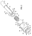
- the apparatus 10 is installed on the plunger rod 12 that extends to a reduced diameter end portion 16 which has a slot 18 (see FIG. 2), through which a shank portion 20 of the blade 14 is inserted.
- the blade 14 With regard to the shape of the blade 14 described herein, which is a generally typical shape and is commercially available from many manufacturers, it has a shank 20 that is generally of the same thickness as the blade portion 14 but is narrower than the blade portion in that the transition from the shank portion to the blade portion creates a shoulder 22 on each side of the blade.
- the end 24 of the blade 14 may have a notch 26 and the shank preferably has a hole 28 located in it center generally midway between the end 24 and the shoulder 22 in the longitudinal direction of the blade, all of which is shown in FIG. 5.
- the apparatus 10 has an outer sleeve, indicated generally at 30, which has a generally hollow cylindrical configuration with a reduced diameter end wall 32 that has an opening 34 that is sized slightly larger than the diameter of the end portion 16 of the plunger rod 12 and also slightly larger than the width of the shank portion 20 of the blade 14 so that the shank portion can be inserted into the slot 18 of the rod end portion 16 and the opening 34.
- the outer sleeve 30 has a thickened portion 36 that has a generally square shape and increases from a relatively small thickness at end 38 and to a thicker portion at the opposite end 40, with a transverse end wall 42 providing a gripping surface for a user to more easily rotate the outer sleeve 30 in the counterclockwise direction indicated by the arrow 44 to place the apparatus in an unclamped position.
- a second thickened portion 46 is provided diametrically opposite the portion 36 for enabling symmetrically balanced gripping by a user.
- the outer sleeve 30 has a circumferential elongated slot 48 with a transverse axially aligned extension 50 at one end thereof in which a forward pin 52 is preferably press fit into an opening 54 in the end 16 of the plunger rod 12.
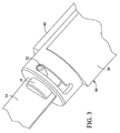
- a diagonal wall 56 is defined by a recess in the inside of the outer sleeve, i.e., the left end portion 58 as shown in FIGS. 1 and 2 is closer to the front end wall 32 than the right end 60.
- the wall 56 has a length that is approximately equal to the length of the slot 48 in that rotation of the pin 52 in the slot 48 extends through an arc that is preferably at least equal to the angular arc between ends 58 and 60 of the wall 56.
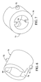
- the apparatus also includes an inner sleeve, indicated generally at 70, which also has a hollow cylindrical configuration and an outer diameter that is sized to closely fit within the outer sleeve 30 and which has an inner diameter that is slightly larger than the outside diameter of the plunger rod end portion 16 on which it slides.
- the inner sleeve has a pair of protrusions 72 that are diametrically opposite one another and an axial recess 74 that extends from the front end rearwardly toward the upper protrusion 72.
- the width of the recess is approximately equal to the diameter of the pin 52 and the axial length of the recess 74 is approximately equal to the axial distance between the ends 58 and 60 of the groove 56. In this way, the inner sleeve 70 can move in the axial distance by an amount equal to the axial distance between ends 58 and 60, but is restrained from rotation by virtue of the pin 52 riding in the recess 74.
- the outer sleeve 30 has a recess diametrically opposed to the recess 56 that is virtually identical to it, but diametrically opposed.
- the protrusion 72 is adapted to fit within the recess 56 and the opposite protrusion similarly engages the recess slot on the opposite side of the outer sleeve 30, so that when there is relative rotational movement between the inner sleeve and the outer sleeve, the angular orientation of the slot 56 will cause axial movement of the inner sleeve 70 relative to the outer sleeve 30. As is best shown in FIG.
- the inner sleeve 70 also has a pair of radially oriented inwardly extending ribs 76 that are diametrically opposite one another that are configured to fit within the slot 18 of the end portion 16 of the plunger rod 12 which prevents rotational movement of the inner sleeve 70 relative to the outer sleeve or the plunger rod 12.
- the apparatus also includes a compression spring 78 which bears against the inner sleeve 70 and against a spring retainer 80.
- the spring 78 has an inside diameter that is slightly larger than the end portion 16 of the plunger rod so that it fits over the same.
- the spring retainer 80 has an inside diameter that is only slightly larger than the outside diameter of the end portion 16 and slides on it until it reaches an annular shoulder 82 that is formed by the end portion 16 being of a slightly smaller diameter than the main portion of the cylindrical plunger rod 12.
- a detente 84 is provided which fits into an opening 85 on the bottom side of the end portion 16 below the slot 18.
- the detente 84 has a conical upper end portion 86 and a bottom end 88 that may be of a hemispherical shape or at least slightly curved.
- the inner sleeve 70 has an inclined or ramped surface 90 that is formed in the front end of its top portion which is configured to engage the detente 84 when the apparatus is in its clamped position, i.e., when the inner sleeve 70 is at its most forward position relative to the outer sleeve 30. This occurs when the protrusion 72 is at the left end 58 as shown in FIG. 1. In this position, the inclined ramp surface 90 bears against the detente 84 and presses the conical portion 86 thereof into the opening 28 of the blade 14 to thereby firmly clamp the blade 14 so that it cannot be easily removed.
- the apparatus when a blade 14 is to be inserted into the apparatus, the apparatus is in its unclamped position which is different from the clamped position shown in FIG. 1 in that the outer sleeve 30 is rotated in the counterclockwise direction of the arrow 44 so that the pin 52 is at the opposite end or left end of the slot 48 as shown in FIG. 1.
- the force of the spring will cause the inner sleeve to be moved forwardly or left in FIG. 1 which in turn causes the outer sleeve 30 to be moved relative to the pin so that it engages the transverse extension 50.
- it When it reaches that point, it is in the unclamped position and it will be retained in this position until a blade is inserted into the apparatus.
- the blade is to be subsequently removed, a user will grip the outer sleeve and rotate it counterclockwise in the direction of the arrow 44. When it reaches the position where the pin 52 is in line with the transverse extension 50, it will be quickly moved to the left which will eject the blade 14 from the apparatus.
- the second preferred embodiment is similar in principle to the first in that it has an unclamped and clamped position and the apparatus is normally in an unclamped position when no blade is inserted in it and upon insertion of a blade a predetermined distance, it is released to move toward the clamped position. Similarly, when it is manually rotated toward the unclamped position, it will eject the blade when it approaches the unclamped position. Rather than moving an inclined surface in an axial direction to move the detente into the aperture in the shank of the blade 14, this preferred embodiment has a ramped or cam surface that engages the detente as a result of rotation of a clamping collar.
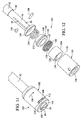
- the clamping apparatus is indicated generally at 100 and is mounted on a plunger rod end portion 16 that is substantially similar to the rod end portion 16 of the first preferred embodiment. It also has a slot 18 as well as a flange 82 that is formed as a result of the diameter of the end portion 16 being less than the diameter of the main portion of the rod 12.
- the apparatus 100 has a generally cylindrically shaped hollow control sleeve, indicated generally at 102, that has a forward end portion 104 and an opening 106 that is slightly larger than the outer diameter of the end portion 16.
- the plunger rod also has an opening 54 in which a pin 108 is inserted and which extends outwardly so as to ride in a circumferential elongated slot 110 that has a transverse extension 112 that is directed rearwardly.
- the configuration of the slots 110 and the extension 112 is substantially similar to the slot and extension 48 and 50 of the first preferred embodiment.
- a clamping collar 124 has a generally hollow cylindrical configuration with the outside diameter being slightly smaller than the inside diameter of the control sleeve 102 so that it fits within it.
- the inside surface of the clamping collar 124 is generally cylindrical in shape but has a portion 126 that has an arc of approximately 90° that increases in its radial distance from the center of the clamping collar beginning at location 128 shown in FIG. 15 and increasing to point 130 which defines a cam surface 132.
- the clamping collar 124 has an axial groove in its outside surface 134 configured to receive an axial rib 136 that is formed on the inside of the control sleeve 102. This interlocking rib and groove configuration causes the control sleeve 102 and clamping collar 124 to rotate together during operation of the apparatus 100.
- the clamping collar also has an aperture 136 that extends substantially the full length of the clamping collar and is sized to receive a transverse end leg 138 of a torsion spring 140.
- An opposite leg 142 is oriented in a radial direction in the center of the spring so that it fits within the slot 18 of the plunger end portion 16. This secures the end portion 142 from rotation so that the opposite end portion 138 when inserted into the aperture 136 creates a torsional force applied to the clamping collar 124 and the control sleeve 102 if they are rotated relative to the position of the end 142.
- a generally cylindrical support ring 144 has a reduced diameter forward portion 146 that defines an annular shoulder 148 that is sized to engage the rear end surface of the control sleeve 102.
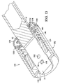
- the support ring 144 also has a rearward extension 152 (see FIGS. 13 and 14) that fits on the end portion 16 of the plunger rod 12.
- a compression spring 154 bears against the support ring 144 as well as against a generally cup-shaped spring retainer 156.
- the inside diameter of the rear end of the spring retainer is sized to closely fit the diameter of the end portion 16 and it contacts and is held by the annular shoulder 82 of the plunger rod 12.
- a detente 158 is provided and fits into an aperture 160 (see FIGS. 14 and 15) in the end portion 16 of the plunger rod.
- the axial position of the aperture 160 and the aperture 54 are different as readily shown in FIG. 14.
- a smaller circular recess 162 is preferable ground into the face of the slot 18 adjacent to the conical portion of the detente 158 to assure that the detente 158 will firmly engage the blade 14 when it is inserted into the apparatus.
- the detente 158 engages the opening 28 of the blade shank 20.
- FIG. 11 which shows the apparatus in either its clamped or unclamped position
- the pin 108 will be located in the slot the extension 112. This holds the apparatus in this unclamped position.
- the shoulders 22 of the blade will engage the front end wall 104 of the control sleeve 102 and with sufficient force applied will move the control sleeve 102 in the rearward direction which will release the pin 108 from the slot extension 112 and biasing force resulting from the torsion spring 140 will rotate the control sleeve 102 as well as the clamping collar 124 in the clockwise direction as shown by arrow 164.
- a user manually rotates the control sleeve 102 in the counterclockwise direction, i.e., the direction opposite the arrow 164, which causes the cam surface 132 to release the detente 158 and when the rotation is sufficient so that the pin 108 is axially aligned with the transverse extension 112, the compression spring will force the spring support and control sleeve forwardly which causes the pin to enter the transverse slot 112 which is the unclamped position of the apparatus.
- the movement of the control sleeve 102 forwardly normally ejects the blade as a result of the front and wall 104 pushing the blade from the slot 18.
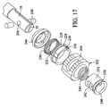
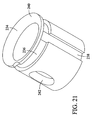
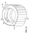
- the apparatus 200 has a cam surface that also engages a detente by rotation thereof.
- the assembled apparatus is indicated generally at 200 and is shown to be installed on a plunger rod 12 having a slightly reduced diameter end portion 16 which thereby forms the shoulder 82 as shown with regard to the prior described embodiments.
- the end portion 16 has a slot 18 for receiving the blade 14 which has the same configuration as has been described with regard to the first and second preferred embodiments.
- the apparatus 200 has a clamping collar, indicated generally at 202, that has an elongated slot 204 in which a pin 206 which is preferably force fit in an aperture 208 in the upper side of the end portion 16. Because the pin is secured in the plunger rod end portion 16 and the diameter of the pin is comparable to the width of the slot 204, the only movement that is permitted by the clamping collar 202 is rotational movement.
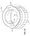
- the clamping collar 202 has a radially inwardly directed protrusion 210 located at the front end thereof that is relatively thin and narrow as shown in FIG. 20.
- the clamping collar 202 also has plurality of small ramp-like protrusions 212 as well as two larger protrusions 214 which facilitate gripping by a user to rotate the clamping collar to the unclamped position as will be hereinafter explained.
- the clamping collar also has an axial rib 216 in the rear portion thereof for engaging a recess in a support ring 218.
- the rear part of the support ring 218 has an enlarged end forming a shoulder 224 that is adapted to contact the end surface of the clamping collar 202.
- the main part of the support ring 218 is adapted to slide within the rear portion of the clamping collar 202. By virtue of the complementary rib and recess construction, the support ring 218 and clamping collar 202 will necessarily rotate together as is desired.
- the support ring 218 also has an axially oriented aperture or slot 226 that is adapted to receive the transverse end 228 of a torsion spring 230, the opposite end thereof being radially oriented and configured to fit within the slot 18 of the plunger rod end 16.
- a generally hollow cylindrical control sleeve 234 fits around the plunger end portion 16 and inside of the clapping collar 202.
- the control sleeve 234 has an annular groove 236 near the front portion 236 located near its front and the annular groove 236 merges with a perpendicular axially oriented groove 238 that extends from the annular groove 236 to the rear end of the control sleeve 234.
- the control sleeve 234 also has a flared front 240, the inside surface of which is generally configured to conform with the shape of shoulders of many commercially available blades 14.
- the control sleeve 234 also has an elongated opening 242 through which the pin 206 passes. This enables the control sleeve 234 to move in the axial direction, but is precluded from rotating relative to the plunger rod end portion 16.
- a compression spring 244 is located inside of the clamping collar 202 and has a diameter that is approximately equal to that of the control sleeve 234 so that the front end of the spring 244 bears against the rear surface of the control sleeve 234 when the apparatus is assembled.
- the spring 244 has a diameter that is only slightly larger than the diameter of the end portion 16, and the rear end of the spring 244 bears against a spring retainer 246.
- the spring retainer 246 has an internal diameter that is only slightly larger than the diameter of the end portion 16 but smaller than the diameter of the main part of the plunger rod 12 so that it is restrained by the shoulder 82 of the plunger rod.
- a detente 248 fits within the aperture 250 in the end portion 16 of the plunger rod 12.
- the detente 248 also has a conical configuration at the end which engages the blade 14 and a curved opposite end portion.
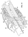
- the detente 248 is moved toward and away from the blade 14 during operation by virtue of a cam surface 252 that is shown in FIG. 19 and which extends from approximately location 254 to location 256, with the location 256 having a larger radius from the center of the apparatus than the location 254. In this regard, it is similar to the cam surface of the second embodiment.
- the protrusion 210 of the clamping collar 202 is located in the axial slot 238 of the control sleeve 234.
- the control sleeve 234 is moved axially in the reverse direction until the protrusion 210 is aligned with the annular groove 236 of the control sleeve 234, whereupon the bias of the torsion spring 230 will rotate the support ring 218 and the clamping collar 202 so that it moves in a clockwise direction to its clamping position shown in FIG. 19.
- all embodiments of the present invention are adapted to apply a generally uniform holding force regardless of the thickness of the blade or other tool accessory that is installed in the apparatus.
- the control sleeve 234 When the control sleeve 234 is pushed rearwardly to release the clamping collar, it loads the compression spring 244. Also, the torsion spring 230 causes the clamping collar and support ring to rotate to the position as shown in FIG. 19 where the blade would be locked in place. To unclamp the blade, the user merely needs to rotate the clamping collar in the counterclockwise direction as shown in FIGS. 16, 18 and 19, which will enable the detente 248 to be released from the blade.
- the materials from which the present apparatus are made is preferably steel or other hard metal, with the exception that the spring retainers do not normally experience excessive stresses and therefore may be fabricated from plastic or plastic-like material.
- the invention provides a tool-less blade clamping apparatus 10, 100, 200 for a reciprocating tool of the type which has a reciprocating plunger 12 with at least one radially oriented aperture 54 and a blade receiving slot 18 at its forward end for receiving a blade 14 of the type which has a shank portion 20 with a hole 28 and at least one outwardly extending shoulder 22 between the distal end of the shank and a blade portion, the shank being configured to be inserted in the slot, the apparatus being configured to be attached to the plunger and having an opening for receiving the blade shank therein and in the slot, said apparatus comprising: said apparatus having an unclamped position and a clamped position wherein the shank portion of the blade can be inserted into said opening when it is in said unclamped position and be securely retained therein when in said clamped position; said apparatus being biased toward said clamped position; said apparatus being operable to maintain its unclamped position when placed in said unclamped position; said apparatus being released when the at least one shoulder 22 of the blade shank
- the clamping apparatus comprises at least one spring 78, 140, 230 biasing said apparatus toward said clamped position.
- the clamping apparatus comprises a releasable retaining mechanism 30, 84; 102, 124; 202, 234, 244 for holding said apparatus in its unclamped position when placed in said unclamped position; said retaining mechanism being released when the blade shank portion is inserted into said opening and slot a predetermined distance to thereby place said clamping apparatus in said clamped position; said clamping apparatus pushing the blade shank portion outwardly there-from when said retaining mechanism is moved to said unclamped position.
Landscapes
- Engineering & Computer Science (AREA)
- Mechanical Engineering (AREA)
- Sawing (AREA)
- Dental Tools And Instruments Or Auxiliary Dental Instruments (AREA)
- Cutting Tools, Boring Holders, And Turrets (AREA)
- Surgical Instruments (AREA)
Priority Applications (2)
| Application Number | Priority Date | Filing Date | Title |
|---|---|---|---|
| EP20070115116 EP1857209B1 (fr) | 2004-01-16 | 2005-01-14 | Dispositif de serrage de lames sans outil pour un outil à mouvement alternatif |
| EP20070115118 EP1857210B1 (fr) | 2004-01-16 | 2005-01-14 | Dispositif de serrage de lames sans outil pour un outil à mouvement alternatif |
Applications Claiming Priority (2)
| Application Number | Priority Date | Filing Date | Title |
|---|---|---|---|
| US10/760,110 US7871080B2 (en) | 2004-01-16 | 2004-01-16 | Tool-less blade clamping apparatus for a reciprocating tool |
| US760110 | 2004-01-16 |
Related Child Applications (2)
| Application Number | Title | Priority Date | Filing Date |
|---|---|---|---|
| EP20070115116 Division EP1857209B1 (fr) | 2004-01-16 | 2005-01-14 | Dispositif de serrage de lames sans outil pour un outil à mouvement alternatif |
| EP20070115118 Division EP1857210B1 (fr) | 2004-01-16 | 2005-01-14 | Dispositif de serrage de lames sans outil pour un outil à mouvement alternatif |
Publications (2)
| Publication Number | Publication Date |
|---|---|
| EP1555078A1 true EP1555078A1 (fr) | 2005-07-20 |
| EP1555078B1 EP1555078B1 (fr) | 2007-12-05 |
Family
ID=34620729
Family Applications (3)
| Application Number | Title | Priority Date | Filing Date |
|---|---|---|---|
| EP20070115118 Ceased EP1857210B1 (fr) | 2004-01-16 | 2005-01-14 | Dispositif de serrage de lames sans outil pour un outil à mouvement alternatif |
| EP20050000710 Ceased EP1555078B1 (fr) | 2004-01-16 | 2005-01-14 | Dispositif de serrage de lames sans outil pour un outil à mouvement alternatif |
| EP20070115116 Ceased EP1857209B1 (fr) | 2004-01-16 | 2005-01-14 | Dispositif de serrage de lames sans outil pour un outil à mouvement alternatif |
Family Applications Before (1)
| Application Number | Title | Priority Date | Filing Date |
|---|---|---|---|
| EP20070115118 Ceased EP1857210B1 (fr) | 2004-01-16 | 2005-01-14 | Dispositif de serrage de lames sans outil pour un outil à mouvement alternatif |
Family Applications After (1)
| Application Number | Title | Priority Date | Filing Date |
|---|---|---|---|
| EP20070115116 Ceased EP1857209B1 (fr) | 2004-01-16 | 2005-01-14 | Dispositif de serrage de lames sans outil pour un outil à mouvement alternatif |
Country Status (3)
| Country | Link |
|---|---|
| US (3) | US7871080B2 (fr) |
| EP (3) | EP1857210B1 (fr) |
| DE (1) | DE602005003595T2 (fr) |
Cited By (3)
| Publication number | Priority date | Publication date | Assignee | Title |
|---|---|---|---|---|
| WO2013107331A1 (fr) * | 2012-01-16 | 2013-07-25 | Bosch Power Tools (China) Co., Ltd. | Dispositif de serrage de lame de scie |
| CN116236265A (zh) * | 2021-12-07 | 2023-06-09 | 苏州微创脊柱创伤医疗科技有限公司 | 一种固定夹 |
| CN117300257A (zh) * | 2023-10-25 | 2023-12-29 | 无锡市新菊电动工具有限公司 | 一种摆动铲锯片快速夹持机构 |
Families Citing this family (51)
| Publication number | Priority date | Publication date | Assignee | Title |
|---|---|---|---|---|
| CN1224484C (zh) * | 2002-05-27 | 2005-10-26 | 苏州宝时得电动工具有限公司 | 往复电动工具 |
| US7871080B2 (en) * | 2004-01-16 | 2011-01-18 | Robert Bosch Gmbh | Tool-less blade clamping apparatus for a reciprocating tool |
| US7543832B2 (en) * | 2006-01-26 | 2009-06-09 | Polaris Industries Inc. | Variable rate stabilizer bar |
| DE102006043682A1 (de) * | 2006-09-18 | 2008-03-27 | Robert Bosch Gmbh | Einspannvorrichtung für eine Hubsägemaschine |
| US20080179840A1 (en) * | 2007-01-31 | 2008-07-31 | Chin-Tan Huang | Chuck device for a hand tool |
| US8020876B2 (en) * | 2007-04-04 | 2011-09-20 | Hung Wei Lin | Tool having clamping chuck |
| TW200911490A (en) * | 2007-09-11 | 2009-03-16 | Mobiletron Electronics Co Ltd | Saw gripping device for sawing machine |
| US8813372B2 (en) * | 2007-09-14 | 2014-08-26 | Milwaukee Electric Tool Corporation | Blade clamp mechanism |
| US8181973B2 (en) * | 2008-05-05 | 2012-05-22 | Robert Bosch Gmbh | Clamping apparatus for a reciprocating tool |
| US8230607B2 (en) * | 2008-05-09 | 2012-07-31 | Milwaukee Electric Tool Corporation | Keyless blade clamp for a power tool |
| US8465492B2 (en) * | 2008-06-30 | 2013-06-18 | Medtronic Xomed, Inc. | Chuck for reciprocating surgical instrument |
| US8800999B2 (en) * | 2009-02-27 | 2014-08-12 | Black & Decker Inc. | Bit retention device |
| CN102069475B (zh) * | 2009-11-20 | 2013-08-21 | 南京德朔实业有限公司 | 一种动力榔头 |
| US8622400B2 (en) * | 2010-04-22 | 2014-01-07 | Yih Cheng Factory Co., Ltd | Quick and reliable tool |
| US20120031815A1 (en) * | 2010-08-05 | 2012-02-09 | Len Walter Enterprises, LLC | Pill sorting stylus tool and pill sorting system |
| DE102011014497A1 (de) * | 2011-03-18 | 2012-09-20 | Wsengineering Gmbh & Co. Kg | Halterung für ein Oszillationssägeblatt |
| US9475141B2 (en) | 2011-08-04 | 2016-10-25 | Milwaukee Electric Tool Corporation | Reciprocating saw blade |
| US20130075985A1 (en) * | 2011-09-22 | 2013-03-28 | Long Chang | Conversion device of power tool |
| JP5746645B2 (ja) | 2012-02-03 | 2015-07-08 | 株式会社マキタ | 作業工具 |
| US9156097B2 (en) | 2012-03-20 | 2015-10-13 | Milwaukee Electric Tool Corporation | Reciprocating saw blade clamp |
| USD688543S1 (en) | 2012-03-20 | 2013-08-27 | Milwaukee Electric Tool Corporation | Saw blade |
| USD687275S1 (en) | 2012-03-20 | 2013-08-06 | Milwaukee Electric Tool Corporation | Saw blade |
| US8935909B2 (en) | 2012-06-12 | 2015-01-20 | Mtd Products Inc | Replaceable mower blade and assembly |
| US8931248B2 (en) | 2012-06-12 | 2015-01-13 | Mtd Products Inc | Replaceable mower blade assembly |
| US20140197609A1 (en) * | 2013-01-16 | 2014-07-17 | A-Tina Tools Co., Ltd. | Hand Tool Plate Clamp |
| WO2014205260A1 (fr) * | 2013-06-19 | 2014-12-24 | Eca Medical Instruments | Raccord à blocage coulissant |
| WO2014205264A1 (fr) | 2013-06-19 | 2014-12-24 | Eca Medical Instruments | Raccord de verrouillage de déplacement |
| CN103522229B (zh) * | 2013-10-21 | 2016-07-06 | 上海齐迈五金有限公司 | 一种旋转夹紧机构及其使用方法 |
| WO2015168359A1 (fr) | 2014-04-30 | 2015-11-05 | Gyrus Acmi, Inc., D.B.A. Olympus Surgical | Outil rotatif ayant un ensemble de couplage amélioré |
| USD729600S1 (en) | 2014-05-06 | 2015-05-19 | Milwaukee Electric Tool Corporation | Saw blade |
| EP3188584B1 (fr) | 2014-09-05 | 2020-04-08 | MTD Products Inc | Couteaux de tondeuse à changement rapide |
| US9816797B1 (en) * | 2015-07-23 | 2017-11-14 | The United States Of America As Represented By The Secretary Of The Navy | Modular angular alignment clocking mechanism |
| DE102015218339A1 (de) * | 2015-09-24 | 2017-03-30 | Robert Bosch Gmbh | Handgeführte Hubsäge mit einer Verlaufskorrekturvorrichtung und Verfahren zur Verlaufskorrektur |
| US10589439B2 (en) * | 2016-06-21 | 2020-03-17 | Globe Food Equipment Company | Blade mounting and removal tool, system, and product slicer |
| EP3269481A1 (fr) * | 2016-07-11 | 2018-01-17 | HILTI Aktiengesellschaft | Dispositif de guidage pour une lame de scie |
| JP7096032B2 (ja) | 2018-03-28 | 2022-07-05 | 株式会社マキタ | マルチツール |
| CN214978174U (zh) * | 2018-06-14 | 2021-12-03 | 米沃奇电动工具公司 | 刀片夹具和往复锯 |
| TWM594510U (zh) * | 2019-05-23 | 2020-05-01 | 鑽全實業股份有限公司 | 工具轉接頭快拆結構 |
| US11738397B2 (en) | 2019-06-12 | 2023-08-29 | Black & Decker Inc. | Reciprocating saw |
| US10814410B1 (en) * | 2019-06-18 | 2020-10-27 | Zheng Kai Hardware Products (Nantong) Co., Ltd. | Saw blade hand tool structure |
| US11590593B2 (en) | 2019-11-28 | 2023-02-28 | Makita Corporation | Power tool |
| US11660690B2 (en) | 2019-11-28 | 2023-05-30 | Makita Corporation | Power tool |
| JP7422538B2 (ja) | 2019-12-26 | 2024-01-26 | 株式会社マキタ | 作業工具 |
| JP7330914B2 (ja) | 2020-02-13 | 2023-08-22 | 株式会社マキタ | 振動工具 |
| JP7532227B2 (ja) | 2020-11-27 | 2024-08-13 | 株式会社マキタ | 往復動工具 |
| CN115570205B (zh) * | 2021-06-21 | 2023-10-13 | 南京泉峰科技有限公司 | 切割工具 |
| CN114191776B (zh) * | 2021-12-21 | 2022-09-09 | 李萌 | 一种临产后医疗产科助产活动器 |
| US12420345B2 (en) | 2022-02-22 | 2025-09-23 | Techtronic Cordless Gp | Blade clamp for reciprocating saw |
| CN114587494B (zh) * | 2022-03-24 | 2023-03-28 | 无锡市第九人民医院 | 一种用于骨科实验的钻骨取骨器 |
| US20240001456A1 (en) * | 2022-06-30 | 2024-01-04 | Robert Bosch Gmbh | Mandrel Assembly for Use With a Rotary Tool |
| US12172265B2 (en) | 2022-08-25 | 2024-12-24 | Robert Bosch Gmbh | Mandrel assembly for use with a rotary tool |
Citations (2)
| Publication number | Priority date | Publication date | Assignee | Title |
|---|---|---|---|---|
| US20020017026A1 (en) * | 2000-05-16 | 2002-02-14 | Yasuhiro Kakiuchi | Blade mounting devices |
| WO2003099523A2 (fr) * | 2002-05-27 | 2003-12-04 | Positec Power Tools (Suzhou) Co., Ltd. | Outil a commande mecanique a mouvement alternatif |
Family Cites Families (58)
| Publication number | Priority date | Publication date | Assignee | Title |
|---|---|---|---|---|
| US36269A (en) * | 1862-08-26 | Improvement in churns | ||
| US3583716A (en) * | 1969-02-06 | 1971-06-08 | Singer Co | Chuck assembly for power tools |
| US3823473A (en) * | 1970-11-09 | 1974-07-16 | S Hoffman | Blade attachment means for saber saw assembly |
| US3750283A (en) * | 1970-11-09 | 1973-08-07 | S Hoffman | Blade attachment means for saber saw assembly |
| US3927893A (en) | 1974-01-11 | 1975-12-23 | Skil Corp | Collet assembly for a reciprocating tool |
| US4106181A (en) * | 1976-08-09 | 1978-08-15 | American Safety Equipment Corporation | Quick release mechanism for oscillating saw blade |
| US4083112A (en) | 1976-12-06 | 1978-04-11 | The Black And Decker Manufacturing Company | Clamp arrangement for clamping saw blades to the blade holder of a power driven saw |
| US4299402A (en) * | 1978-05-02 | 1981-11-10 | Hoffman Simon J | Blade holder for saber saw |
| US4470196A (en) * | 1979-08-01 | 1984-09-11 | Hoffman Simon J | Holder for saber saw blade |
| US4601477A (en) * | 1985-01-10 | 1986-07-22 | The Singer Company | Sabre saw blade clamp |
| DE8506874U1 (de) | 1985-03-09 | 1985-06-05 | Rems-Werk Christian Föll und Söhne GmbH & Co, 7050 Waiblingen | Sägeblatt für eine elektrische Stichsäge |
| WO1989008524A1 (fr) | 1988-03-15 | 1989-09-21 | Robert Bosch Gmbh | Scie alternative a decouper |
| DE4102011C2 (de) | 1990-05-31 | 1996-01-25 | Atlas Copco Elektrowerkzeuge | Einrichtung zum Festspannen des Sägeblatts von handgeführten Stichsägemaschinen |
| US5103565A (en) * | 1991-09-26 | 1992-04-14 | Skil Corporation | Blade holder for reciprocating saws |
| DE4138986A1 (de) * | 1991-11-27 | 1993-06-03 | Atlas Copco Elektrowerkzeuge | Spanneinrichtung fuer eine stichsaegemaschine |
| DE9202611U1 (de) * | 1992-02-28 | 1993-06-24 | Robert Bosch Gmbh, 7000 Stuttgart | Werkzeughalter |
| NL9201371A (nl) * | 1992-07-29 | 1994-02-16 | Emerson Electric Co | Zaagbladfixatie-inrichting. |
| US5421232A (en) * | 1992-09-26 | 1995-06-06 | Black & Decker Inc. | Reciprocating saw |
| USRE36269E (en) | 1993-01-21 | 1999-08-17 | Minnesota Mining And Manufacturing Company | Saw blade retention system |
| US5340129A (en) * | 1993-01-21 | 1994-08-23 | Minnesota Mining And Manufacturing Company | Saw blade retention system |
| US5575071A (en) * | 1994-01-19 | 1996-11-19 | Porter-Cable Corporation | Toolless quickchange blade clamp for reciprocating saws |
| JP3212792B2 (ja) * | 1994-02-10 | 2001-09-25 | 株式会社マキタ | ジグソー |
| DE69510783T2 (de) | 1994-04-12 | 1999-12-02 | Phillips, Alan G. | Schnellwechselsägeblattspannvorrichtung, bedienbar ohne zusätzliches werkzeug, für hin- und hergehende sägen |
| US5443276A (en) * | 1994-07-22 | 1995-08-22 | S-B Power Tool Company | Self-locking blade holder |
| US6237231B1 (en) * | 1994-11-29 | 2001-05-29 | Milwaukee Electric Tool Corporation | Keyless clamp assembly for reciprocating tool |
| US5661909A (en) * | 1994-12-02 | 1997-09-02 | Makita Corporation | Blade mounting device in cutting tool |
| AU696069B2 (en) * | 1994-12-13 | 1998-09-03 | Linvatec Corporation | Surgical cutting device with safety interlock |
| DE19501635A1 (de) * | 1995-01-20 | 1996-08-01 | Metabowerke Kg | Vorrichtung zur Aufnahme eines einendig einspannbaren Sägeblattes |
| US5765463A (en) * | 1995-02-15 | 1998-06-16 | Makita Corporation | Blade mounting device in cutting tool |
| DE19509539A1 (de) * | 1995-03-16 | 1996-09-19 | Bosch Gmbh Robert | Stichsägemaschine |
| US5573255A (en) * | 1995-05-05 | 1996-11-12 | Power Tool Holders, Inc. | Quick release chuck device for saw blades |
| US6295736B1 (en) * | 1995-06-09 | 2001-10-02 | Black & Decker Inc. | Blade ejection mechanism for a saw blade clamping arrangement of a power tool |
| US6009627A (en) * | 1995-06-09 | 2000-01-04 | Black & Decker Inc. | Saw blade clamping arrangement for a power tool |
| US6023848A (en) * | 1995-06-09 | 2000-02-15 | Black & Decker Inc. | Saw blade clamping arrangement for a power tool |
| US5647133A (en) * | 1995-06-09 | 1997-07-15 | Black & Decker Inc. | Saw blade clamping arrangement for a power tool |
| US5724742A (en) * | 1995-07-27 | 1998-03-10 | Black & Decker Inc. | Reciprocating saw blade clamp |
| US6725548B1 (en) * | 1996-03-01 | 2004-04-27 | Milwaukee Electric Tool Corporation | Keyless blade clamp mechanism |
| GB9604463D0 (en) | 1996-03-01 | 1996-05-01 | Black & Decker Inc | A saw blade clamp |
| WO1997031745A2 (fr) | 1996-03-01 | 1997-09-04 | Milwaukee Electric Tool Corporation | Mecanisme de blocage de lame sans clavette |
| DE69714651T2 (de) * | 1996-05-23 | 2003-03-13 | Black & Decker Inc., Newark | Sägeblattaufspannvorrichtung für ein motorisiertes Werkzeug |
| US5810367A (en) * | 1996-08-09 | 1998-09-22 | S-B Power Tool Company | Wrenchless holder for working tools |
| GB2322593B (en) * | 1997-02-28 | 1999-05-05 | Bosch Gmbh Robert | Clamping mechanism for a power tool |
| US5987758A (en) * | 1997-10-28 | 1999-11-23 | Ryobi North America, Inc. | Quick-change blade clamp |
| DE19819527A1 (de) | 1998-04-30 | 1999-11-04 | Scintilla Ag | Hubstange für eine Elektrohandwerkzeugmaschine |
| DE19819528A1 (de) | 1998-04-30 | 1999-11-04 | Scintilla Ag | Handwerkzeugmaschine |
| US6209208B1 (en) | 1998-10-09 | 2001-04-03 | Milwaukee Electric Tool Corporarion | Keyless blade clamp mechanism |
| JP3858529B2 (ja) * | 1998-10-23 | 2006-12-13 | 日立工機株式会社 | セーバソーのブレード着脱機構 |
| JP3542511B2 (ja) * | 1998-12-24 | 2004-07-14 | 株式会社マキタ | 往復切断工具の刃具取り付け装置 |
| US6453565B1 (en) * | 2001-01-24 | 2002-09-24 | Porter-Cable/Delta | Universal blade adapter |
| US7040023B2 (en) * | 2002-11-25 | 2006-05-09 | Eastway Fair Company Limited | Toolless blade holder for a reciprocating tool |
| US6808182B2 (en) * | 2002-12-27 | 2004-10-26 | Zangzhou I Con Machinery Co., Ltd. | Quick release or connect chuck device |
| US6877751B2 (en) * | 2003-03-27 | 2005-04-12 | Chiu Yung Hsing | Insertable tool connector |
| CN2617509Y (zh) * | 2003-04-14 | 2004-05-26 | 苏州宝时得电动工具有限公司 | 工作元件的快换夹紧机构 |
| US6851194B1 (en) * | 2003-10-06 | 2005-02-08 | Motomax Electric Co., Ltd. | Reciprocating saw having a blade holding device |
| US7871080B2 (en) * | 2004-01-16 | 2011-01-18 | Robert Bosch Gmbh | Tool-less blade clamping apparatus for a reciprocating tool |
| US7107690B2 (en) * | 2004-05-24 | 2006-09-19 | Choon Nang Electrical Appliance Mfy., Ltd. | Electric cutting tool |
| CN200995304Y (zh) * | 2007-01-16 | 2007-12-26 | 南京德朔实业有限公司 | 一种锯片快速夹紧装置 |
| US8181973B2 (en) * | 2008-05-05 | 2012-05-22 | Robert Bosch Gmbh | Clamping apparatus for a reciprocating tool |
-
2004
- 2004-01-16 US US10/760,110 patent/US7871080B2/en not_active Expired - Fee Related
-
2005
- 2005-01-14 EP EP20070115118 patent/EP1857210B1/fr not_active Ceased
- 2005-01-14 EP EP20050000710 patent/EP1555078B1/fr not_active Ceased
- 2005-01-14 EP EP20070115116 patent/EP1857209B1/fr not_active Ceased
- 2005-01-14 DE DE200560003595 patent/DE602005003595T2/de not_active Expired - Lifetime
-
2010
- 2010-12-07 US US12/961,772 patent/US8393625B2/en not_active Expired - Fee Related
-
2013
- 2013-03-11 US US13/794,207 patent/US8641049B2/en not_active Expired - Fee Related
Patent Citations (2)
| Publication number | Priority date | Publication date | Assignee | Title |
|---|---|---|---|---|
| US20020017026A1 (en) * | 2000-05-16 | 2002-02-14 | Yasuhiro Kakiuchi | Blade mounting devices |
| WO2003099523A2 (fr) * | 2002-05-27 | 2003-12-04 | Positec Power Tools (Suzhou) Co., Ltd. | Outil a commande mecanique a mouvement alternatif |
Cited By (5)
| Publication number | Priority date | Publication date | Assignee | Title |
|---|---|---|---|---|
| WO2013107331A1 (fr) * | 2012-01-16 | 2013-07-25 | Bosch Power Tools (China) Co., Ltd. | Dispositif de serrage de lame de scie |
| US9744605B2 (en) | 2012-01-16 | 2017-08-29 | Bosch Power Tools (China) Co., Ltd. | Saw blade clamping device |
| DE112013000583B4 (de) * | 2012-01-16 | 2025-08-21 | Robert Bosch Gmbh | Sägeblattspannvorrichtung |
| CN116236265A (zh) * | 2021-12-07 | 2023-06-09 | 苏州微创脊柱创伤医疗科技有限公司 | 一种固定夹 |
| CN117300257A (zh) * | 2023-10-25 | 2023-12-29 | 无锡市新菊电动工具有限公司 | 一种摆动铲锯片快速夹持机构 |
Also Published As
| Publication number | Publication date |
|---|---|
| DE602005003595T2 (de) | 2008-11-13 |
| EP1555078B1 (fr) | 2007-12-05 |
| US7871080B2 (en) | 2011-01-18 |
| DE602005003595D1 (de) | 2008-01-17 |
| US20110074122A1 (en) | 2011-03-31 |
| EP1857209A3 (fr) | 2008-11-26 |
| EP1857210A3 (fr) | 2008-11-26 |
| US8641049B2 (en) | 2014-02-04 |
| US20050156390A1 (en) | 2005-07-21 |
| EP1857209B1 (fr) | 2012-11-28 |
| US8393625B2 (en) | 2013-03-12 |
| EP1857210A2 (fr) | 2007-11-21 |
| EP1857210B1 (fr) | 2012-11-21 |
| EP1857209A2 (fr) | 2007-11-21 |
| US20130193653A1 (en) | 2013-08-01 |
Similar Documents
| Publication | Publication Date | Title |
|---|---|---|
| US7871080B2 (en) | Tool-less blade clamping apparatus for a reciprocating tool | |
| US8181973B2 (en) | Clamping apparatus for a reciprocating tool | |
| US6546633B1 (en) | Reciprocating saw holder | |
| US6612039B2 (en) | Blade mounting devices | |
| US6209208B1 (en) | Keyless blade clamp mechanism | |
| US7040023B2 (en) | Toolless blade holder for a reciprocating tool | |
| EP2386373B1 (fr) | Butée de profondeur pour foret | |
| US8061718B2 (en) | Toolless bitholder for spiral saws | |
| EP1745889B1 (fr) | Accessoire d'un outil rotatif | |
| GB2398540A (en) | Hand saw | |
| CN108290226B (zh) | 锁定卡盘 | |
| US10442009B2 (en) | Drill with removable chuck | |
| EP1294514A1 (fr) | Adaptateur de piece pour outil electrique | |
| JPH07195278A (ja) | 手持ち穿孔機 | |
| US6755424B1 (en) | Quick-Change tool attachment system for a reciprocating power unit | |
| US10835972B2 (en) | Blade clamp for power tool | |
| WO2018089746A1 (fr) | Serre-lame pour outil électrique à mouvement alternatif | |
| JPH081532A (ja) | ドライバ | |
| NZ529752A (en) | Toolless blade holder for a reciprocating tool |
Legal Events
| Date | Code | Title | Description |
|---|---|---|---|
| PUAI | Public reference made under article 153(3) epc to a published international application that has entered the european phase |
Free format text: ORIGINAL CODE: 0009012 |
|
| AK | Designated contracting states |
Kind code of ref document: A1 Designated state(s): AT BE BG CH CY CZ DE DK EE ES FI FR GB GR HU IE IS IT LI LT LU MC NL PL PT RO SE SI SK TR |
|
| AX | Request for extension of the european patent |
Extension state: AL BA HR LV MK YU |
|
| 17P | Request for examination filed |
Effective date: 20051221 |
|
| AKX | Designation fees paid |
Designated state(s): DE FR GB IT |
|
| GRAP | Despatch of communication of intention to grant a patent |
Free format text: ORIGINAL CODE: EPIDOSNIGR1 |
|
| GRAS | Grant fee paid |
Free format text: ORIGINAL CODE: EPIDOSNIGR3 |
|
| GRAA | (expected) grant |
Free format text: ORIGINAL CODE: 0009210 |
|
| AK | Designated contracting states |
Kind code of ref document: B1 Designated state(s): DE FR GB IT |
|
| REG | Reference to a national code |
Ref country code: GB Ref legal event code: FG4D |
|
| REF | Corresponds to: |
Ref document number: 602005003595 Country of ref document: DE Date of ref document: 20080117 Kind code of ref document: P |
|
| ET | Fr: translation filed | ||
| PLBE | No opposition filed within time limit |
Free format text: ORIGINAL CODE: 0009261 |
|
| STAA | Information on the status of an ep patent application or granted ep patent |
Free format text: STATUS: NO OPPOSITION FILED WITHIN TIME LIMIT |
|
| 26N | No opposition filed |
Effective date: 20080908 |
|
| REG | Reference to a national code |
Ref country code: FR Ref legal event code: PLFP Year of fee payment: 12 |
|
| REG | Reference to a national code |
Ref country code: FR Ref legal event code: PLFP Year of fee payment: 13 |
|
| REG | Reference to a national code |
Ref country code: FR Ref legal event code: PLFP Year of fee payment: 14 |
|
| PGFP | Annual fee paid to national office [announced via postgrant information from national office to epo] |
Ref country code: DE Payment date: 20180308 Year of fee payment: 14 Ref country code: GB Payment date: 20180125 Year of fee payment: 14 |
|
| PGFP | Annual fee paid to national office [announced via postgrant information from national office to epo] |
Ref country code: IT Payment date: 20180126 Year of fee payment: 14 Ref country code: FR Payment date: 20180124 Year of fee payment: 14 |
|
| REG | Reference to a national code |
Ref country code: DE Ref legal event code: R119 Ref document number: 602005003595 Country of ref document: DE |
|
| GBPC | Gb: european patent ceased through non-payment of renewal fee |
Effective date: 20190114 |
|
| PG25 | Lapsed in a contracting state [announced via postgrant information from national office to epo] |
Ref country code: FR Free format text: LAPSE BECAUSE OF NON-PAYMENT OF DUE FEES Effective date: 20190131 Ref country code: DE Free format text: LAPSE BECAUSE OF NON-PAYMENT OF DUE FEES Effective date: 20190801 |
|
| PG25 | Lapsed in a contracting state [announced via postgrant information from national office to epo] |
Ref country code: GB Free format text: LAPSE BECAUSE OF NON-PAYMENT OF DUE FEES Effective date: 20190114 |
|
| PG25 | Lapsed in a contracting state [announced via postgrant information from national office to epo] |
Ref country code: IT Free format text: LAPSE BECAUSE OF NON-PAYMENT OF DUE FEES Effective date: 20190114 |