EP1555368B1 - Ferrure pour un mouvement d'inclinaison d'une aile d'un fenêtre de bâtiment ou d'une porte de bâtiment aussi bien une fenêtre ou une porte parallèle glissant et de type oscillo-battant avec un tel ferrure - Google Patents
Ferrure pour un mouvement d'inclinaison d'une aile d'un fenêtre de bâtiment ou d'une porte de bâtiment aussi bien une fenêtre ou une porte parallèle glissant et de type oscillo-battant avec un tel ferrure Download PDFInfo
- Publication number
- EP1555368B1 EP1555368B1 EP04014217A EP04014217A EP1555368B1 EP 1555368 B1 EP1555368 B1 EP 1555368B1 EP 04014217 A EP04014217 A EP 04014217A EP 04014217 A EP04014217 A EP 04014217A EP 1555368 B1 EP1555368 B1 EP 1555368B1
- Authority
- EP
- European Patent Office
- Prior art keywords
- guide
- fitting
- window
- tilting
- guide element
- Prior art date
- Legal status (The legal status is an assumption and is not a legal conclusion. Google has not performed a legal analysis and makes no representation as to the accuracy of the status listed.)
- Revoked
Links
- 230000008878 coupling Effects 0.000 claims description 27
- 238000010168 coupling process Methods 0.000 claims description 27
- 238000005859 coupling reaction Methods 0.000 claims description 27
- 239000000463 material Substances 0.000 claims description 6
- 238000013461 design Methods 0.000 claims description 5
- 210000002105 tongue Anatomy 0.000 claims description 4
- 239000000470 constituent Substances 0.000 claims 1
- 239000011521 glass Substances 0.000 abstract 1
- 229910052751 metal Inorganic materials 0.000 description 4
- 239000002184 metal Substances 0.000 description 4
- 229910000831 Steel Inorganic materials 0.000 description 2
- 239000010959 steel Substances 0.000 description 2
- 229910052782 aluminium Inorganic materials 0.000 description 1
- XAGFODPZIPBFFR-UHFFFAOYSA-N aluminium Chemical compound [Al] XAGFODPZIPBFFR-UHFFFAOYSA-N 0.000 description 1
- 239000003086 colorant Substances 0.000 description 1
- 238000005553 drilling Methods 0.000 description 1
- 238000003780 insertion Methods 0.000 description 1
- 230000037431 insertion Effects 0.000 description 1
- 238000012986 modification Methods 0.000 description 1
- 230000004048 modification Effects 0.000 description 1
- 230000000284 resting effect Effects 0.000 description 1
- 230000000717 retained effect Effects 0.000 description 1
- 238000000926 separation method Methods 0.000 description 1
- 238000012549 training Methods 0.000 description 1
- 238000013022 venting Methods 0.000 description 1
- 230000000007 visual effect Effects 0.000 description 1
Images


Classifications
-
- E—FIXED CONSTRUCTIONS
- E05—LOCKS; KEYS; WINDOW OR DOOR FITTINGS; SAFES
- E05D—HINGES OR SUSPENSION DEVICES FOR DOORS, WINDOWS OR WINGS
- E05D15/00—Suspension arrangements for wings
- E05D15/06—Suspension arrangements for wings for wings sliding horizontally more or less in their own plane
- E05D15/10—Suspension arrangements for wings for wings sliding horizontally more or less in their own plane movable out of one plane into a second parallel plane
- E05D15/1005—Suspension arrangements for wings for wings sliding horizontally more or less in their own plane movable out of one plane into a second parallel plane the wing being supported on arms movable in horizontal planes
- E05D15/1013—Suspension arrangements for wings for wings sliding horizontally more or less in their own plane movable out of one plane into a second parallel plane the wing being supported on arms movable in horizontal planes specially adapted for windows
- E05D15/1015—Suspension arrangements for wings for wings sliding horizontally more or less in their own plane movable out of one plane into a second parallel plane the wing being supported on arms movable in horizontal planes specially adapted for windows with an intermediate tilt position
-
- E—FIXED CONSTRUCTIONS
- E05—LOCKS; KEYS; WINDOW OR DOOR FITTINGS; SAFES
- E05Y—INDEXING SCHEME ASSOCIATED WITH SUBCLASSES E05D AND E05F, RELATING TO CONSTRUCTION ELEMENTS, ELECTRIC CONTROL, POWER SUPPLY, POWER SIGNAL OR TRANSMISSION, USER INTERFACES, MOUNTING OR COUPLING, DETAILS, ACCESSORIES, AUXILIARY OPERATIONS NOT OTHERWISE PROVIDED FOR, APPLICATION THEREOF
- E05Y2900/00—Application of doors, windows, wings or fittings thereof
- E05Y2900/10—Application of doors, windows, wings or fittings thereof for buildings or parts thereof
- E05Y2900/13—Type of wing
- E05Y2900/148—Windows
Definitions
- the invention relates to a fitting according to the preamble of claim 1 and to a Parallelschiebekipp window or a Parallelschiebekipp door according to the preamble of claim 12.
- Parallel sliding tipping doors and windows as well as suitable for such doors or windows fittings are known in various designs.
- a fitting EP 0 231 498 B1 in which two upper opening arms are articulated for an opening or tilting movement of a window or door leaf at the upper area of this wing, with one in a horizontal guide at its other end sliding slider are hingedly connected.
- the two extension arms are additionally connected to each other in the region of their hinged ends connected to the wing via a hinged upper coupling rod to always achieve a parallel position of the upper wing area with the plane of the window frame.
- the coupling rod is seen from the inside of the building arranged in front of the casement.
- the object of the invention is to avoid the disadvantages of known fittings and to further form a fitting of the type mentioned at the beginning, that in a visually appealing appearance, a long, a coupling element or a coupling rod covering cover profile is avoided.
- a fitting according to the patent claim 1 is formed.
- a Parallelschiebekipp window or a Parallelschiebekipp door are designed according to claim 12.
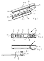
- a special feature of the fitting according to the invention is that the coupling element or the coupling or connecting rod in the upper, i. first guide or in which this guide forming guide rail is received, and connects the two first guide elements together. This makes it possible to provide the coupling element optically not or hardly visible without a cover profile. Furthermore omitted in this training, additional joints between the coupling element and the upper Ausstellarmen.
- the fitting according to the invention represents a particularly cost-effective solution, namely by the saving of the cover profile and by avoiding additional joints for the coupling rod.
- the fitting according to the invention fulfills the requirements of a modern window and door design with the objective that as little as possible of the fitting used in each case is visible.
- 1 is a building window with a floor or frame 2, with a provided in the frame 2, the fixed-field glazing 3 having fixed field and a wing 4.
- the substantially consisting of the sash 5 with the glazing 6 wings is provided by means of a Parallelschiebekipp fitting on the frame 2 such that the wing 4 from its closed position shown in Figure 1, in which it closes the laterally formed by the fixed field in the frame window opening, by moving perpendicular to the window and wing level (Ausstell Gay) in a Ausstelllage ( Figure 3) and then by moving parallel to the window plane in an open position is movable, in which the wing 5 is seen from the inside of the building ago in front of the fixed-field glazing 3.
- the wing 4 is tiltable, for example, for venting from its closed position, as shown in Figure 2.
- Parallelschiebekipp fitting includes u.a. a carriage assembly, which is provided in the region of the underside of the lower horizontal Holmes 5.1 of the sash 5 and consists essentially of two spaced-apart carriage 8.
- Each carriage 8 has a carriage element 9, which is guided with carriage rollers in a lower, horizontal running or guide rail 10 at the lower, horizontal portion 2.1 of the frame 2 and hinged at one end of a lower extension arm 11.
- the other end of each stay arm 11 is pivotally connected to a bearing element 12, with which the respective carriage 8 is attached to the spar 5.1.
- the two carriage elements 9 are connected to each other via a lower coupling rod 13, so that the two extension arms 11, the coupling rod 13, the bearing elements 12 and the joints at the ends of the extension arms 11 form a lower articulated parallelogram. About this is always guaranteed a parallel position of the lower portion of the wing 5 with the plane of the frame in the wing movement perpendicular to the window plane.
- each bearing element 14 is fastened to the sash frame 5 using suitable fastening means, eg screws on its leg 14.
- each Ausstellarms 16 is provided with a pivot pin 17 which engages with ready mounted Parallelschiebekipp fitting in a bearing or joint opening 18 of a slider 19 and there about the longitudinal axis of the pivot pin 17 and also within certain limits about axes radially to this Longitudinal axis is tilted.
- the pivot pin 17 is releasably retained in the hinge opening 18, in the illustrated embodiment, characterized in that the pivot pin 17 at its reaching into the hinge opening 18 end has an annular groove 17.1, which is engaged behind in the joint opening 18 locked pivot pin 17 provided by a slider 19 and actuated by an eccentric 20 locking slide 21, as is also indicated in the figure 7 with broken lines.
- the locking slide 21 has a keyhole-shaped opening 21.1, whose area of greater width corresponds to the outer diameter of the pivot pin 17 and whose area of smaller width corresponds to the diameter of the pivot pin 17 in the region of the annular groove 17.1.
- the slider 19 designed as a narrow cuboid is formed in two parts in the illustrated embodiment, namely consisting of the one shown in FIGS and 7 lower, elongated and on the outer contour approximately parallelepiped sliding part 19.1, in which also the joint opening 18, the eccentric 20 and the locking slide 21 are provided, and from the upper sliding part 19.2 in Figures 5 and 7, which is designed like a strip and mounted slider 19 engages with integrally formed, preferably also designed as detents projections or pins 22 in openings 23 of the slider part 19.1.
- the openings 23 are each provided in pairs at the two ends of the slide part 19.1 and serve, inter alia, to form on the underside of the slide part 19.1 at the two ends of this slider part in each case two spring-like, rounded tongues 24, which will be described in more detail below Way forms a resilient investment or leadership for the respective slider 19 on the two slider longitudinal sides.
- the slide part 19.2 After the attachment of the slide part 19.2 at the top of the slide part 19.1 u.a. also closed the locking slide 21 and for the most part also the eccentric 20 receiving interior of the slide part 19.1.
- the slide part 19.2 is then adjacent to one end of one end of the slide part 19.1.
- the slide part 19.2 protrudes beyond the relevant end of the slide part 19.1 and is there provided with an integrally formed, block-like connecting piece 25 which is located at mounted slide part 19.2 in front of the relevant end or in front of the relevant end face of the slide part 19.1.
- the connector 25 is shaped so that it forms at least on the two longitudinal sides of this slider with respect to the outer contour of the continuation or approximately the continuation of the slider part 19.1 at fully assembled slider 19.
- a bore 26 is provided, which is arranged with its axis parallel to the longitudinal axis of the slider 19 and in the illustrated embodiment, both on the sliding part 19.1 side facing, and on the side facing away from the slider part of the attachment piece 25 is open.
- a clamping screw 27 extending into the bore 26 is furthermore provided.
- the two sliders 19 are slidably received in a common horizontal guide rail 28 in the longitudinal direction of this rail.
- the guide rail 28 is attached to the upper, horizontal part or spar 2.2 of the frame 2 resting, on the building interior facing surface.
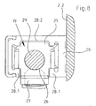
- the guide rail is formed by a C-profile, which is open at its underside of the building window 1 facing bottom.
- the two sliders 19 are each received in this guide rail so that the underside of the slide part 19.1 is located on the lower open side of the guide rail 28 and the four tongues 24 each resiliently abut the slot-shaped opening of the guide rail 28 bounding edges 28.1 of this rail , with which among others a noise-free sliding of the slider 19 is ensured in the guide rail 28.
- the two sliders 19 are further arranged in the guide rail 28 that they included completely including their attachment pieces 25 in the guide rail 28 and their provided with the mounting pieces 25 ends facing each other.
- the slider 19 are connected to each other at these ends, and in fact that the connecting rod 29 engages with one end in a bore 26 of a slider 19 and anchored in this bore 26 with the clamping screw 27 by clamping is.
- the clamping screws 27 on the underside of the guide rail 28 in the region of the local slot-shaped opening of the guide rail are accessible.
- the connecting rod 29 is completely received in the guide rail 28. Between the two ends of the connecting rod 29 is still on the connecting rod 29 an additional, also guided in the guide rail 28 guide piece 30, which in particular prevents rattling by hitting the connecting rod 29 on the guide rail 28.
- the two upper extension arms 16 When the wing 4 is closed, the two upper extension arms 16 are oriented with their longitudinal extent parallel or approximately parallel to the longitudinal axis of the guide rail 28 and are located directly below this guide rail. When tilted or flared window, the two extension arms 16 are each oriented with their longitudinal extent obliquely to the longitudinal axis of the guide rail 28, i. the extension arms 16 close with the longitudinal axis of the guide rail 28 an angle less than 90 °.
- the effective length of the extension arms 16, i. the distance between the two hinges on each extension arm 16 is equal to the effective length of the extension arms 11, i. equal to the distance between the two joints on each stay 11.
- the guide rail 28 is, for example, of a length of a metal profile, e.g. formed of an aluminum profile.
- the sliders 19 and their parts 19.1 and 19.2 consisting of a lubricious material, such as a sliding plastic, but with the exception of the eccentric 20 and locking slide 21, which are made of metal.
- the additional guide piece 30 is made of a lubricious material, for example made of plastic and attached, for example by clamping on the connecting rods 29.
- the two-part slider 19 fills the entire cross section of the guide rail 28, so that the slide part 19.1 at the opening edge 28.1 of the guide rail and the slide part 19.2 supported on the bottom 28.2 of the guide rail 28 and thereby an undesirable separation over the pins 22 and openings 23 with each other connected parts 19.1 and 19.2 is prevented.
- the other elements of the Parallelschiebekipp fitting are made of metal, for example made of steel, namely the two upper Ausstellarme 16 and the associated bearing elements 14 of a metal sheet, such as steel.
- the connecting or coupling rod 29 is not optically disturbing visible.
- An additional long cover for the connecting rod 29 is not required. This results for the building window not only a visually appealing appearance in which as little as possible of the Parallelschiebekipp fitting can be seen, but also an overall very inexpensive solution in particular by saving material.
- cover elements or caps not shown, made of a suitable material, for example of plastic.
- the two-part design of the slider 19 has the advantage that such fittings, which have only the slider part 19.1 corresponding slider can be rebuilt using the slider parts 19.2 and the coupling rod 29 in the context of the invention.
Landscapes
- Engineering & Computer Science (AREA)
- Mechanical Engineering (AREA)
- Wing Frames And Configurations (AREA)
- Window Of Vehicle (AREA)
- Support Devices For Sliding Doors (AREA)
- Door And Window Frames Mounted To Openings (AREA)
Claims (12)
- Ferrure pour un mouvement de projection et de basculement d'un battant d'une fenêtre de bâtiment ou d'une porte de bâtiment, en particulier, d'une fenêtre coulissante/basculante à glissement parallèle ou d'une porte coulissante/basculante à glissement parallèle, avec au moins deux premiers bras de projection (16) pouvant être articulés à respectivement une extrémité dans la zone du côté supérieur d'un cadre de battant (5) et qui sont articulés, par leur autre extrémité, respectivement, sur un élément de guidage (19), qui est aménagé de manière à pouvoir coulisser dans une première glissière (28) qui peut être fixée sur un dormant (2) de la fenêtre ou de la porte, caractérisée en ce que les deux éléments de guidage (19) sont raccordés l'un à l'autre par un élément de couplage (29) reçu dans la première glissière (28) de sorte que, lorsque la ferrure est montée, les articulations des premiers bras de projection (16) forment les sommets d'un quadrilatère articulé ou d'un parallélogramme articulé.
- Ferrure selon la revendication 1, caractérisée en ce que l'élément de couplage est une barre de couplage ou de raccordement (29) logée dans la première glissière (28) et/ou
les premiers éléments de guidage sont des coulisses ou des pièces coulissantes (19) qui sont logées mécaniquement dans la première glissière (28), mais de manière à pouvoir coulisser dans la direction longitudinale de cette glissière. - Ferrure selon la revendication 1 ou 2, caractérisée en ce que
la première glissière (28) peut être fixée en appui sur le côté du dormant (2) tourné vers une face interne du bâtiment; et/ou
la première glissière est un rail de guidage (28), par exemple, un rail de guidage (28) dont la section transversale présente un profil en C. - Ferrure selon l'une quelconque des revendications précédentes, caractérisée en ce que le premier élément de guidage respectif (19) est fabriqué dans un matériau lubrifiant, par exemple, un matériau synthétique.
- Ferrure selon l'une quelconque des revendications précédentes, caractérisée en ce que le raccord articulé est formé de manière amovible entre le premier bras de projection respectif (16) et l'élément de guidage correspondant (19),
dans laquelle il est prévu, par exemple, pour le raccord amovible entre le premier bras de projection (16) et l'élément de guidage correspondant (19), dans l'élément de guidage, un palier (18) avec un dispositif de verrouillage actionnable manuellement (20, 21, 21') pour un pivot (17) situé sur le premier bras de projection (16). - Ferrure selon l'une quelconque des revendications précédentes, caractérisée en ce que les éléments de guidage (19) sont respectivement formés en deux parties, et en ce que le premier élément de couplage (29) est fixé ou peut être fixé sur une première partie (19.2) de chaque élément de guidage (19),
dans laquelle il est prévu, par exemple, sur la première partie de chaque élément de guidage (19), des moyens (25, 26, 27) pour fixer de manière amovible le premier élément de couplage (29), et ces moyens de fixation sont, par exemple, constitués d'un perçage (26) muni de moyens de serrage, par exemple, une vis de serrage (27). - Ferrure selon l'une quelconque des revendications précédentes, caractérisée en ce que l'on prévoit dans la seconde partie (19.1) de l'élément de guidage (19) ou dans un évidement ménagé dans cette partie, les dispositifs de verrouillage (20, 21, 21') destinés au pivot (17) sur le premier bras de projection (16).
- Ferrure selon l'une quelconque des revendications précédentes, caractérisée par des moyens (22, 23) par lesquels les deux parties (19.1, 19.2) de l'élément de guidage en deux parties (19) sont raccordées mécaniquement l'une à l'autre par emboîtement dans une direction axiale perpendiculaire à l'axe longitudinal de la première glissière (28), et en ce que chaque élément de guidage (19) est logé mécaniquement via la première glissière (28), de sorte que celle-ci empêche le raccordement par emboîtement entre les deux parties (19.1, 19.2) de l'élément de guidage en deux parties (19) de se défaire,
dans laquelle, par exemple, les moyens sont constitués de saillies et/ou de tenons (22) ainsi que d'évidements et/ou d'ouvertures (23) recevant ces saillies et/ou tenons (22) sur les parties (19.1, 19.2). - Ferrure selon l'une quelconque des revendications précédentes, caractérisée en ce que l'élément de guidage respectif (19) présente des faces d'appui élastiques qui sont, de préférence, formées par des sections ou languettes moulées (24).
- Ferrure selon l'une quelconque des revendications précédentes, caractérisée en ce qu'elle fait partie d'une ferrure coulissante/basculante glissement parallèle, qui présente également un aménagement de coulisseaux à monter sur une face inférieure du battant (4) ou du cadre (5) du battant, avec au moins deux coulisseaux guidés dans une deuxième glissière inférieure (10) et, articulés respectivement sur une extrémité d'un second bras de projection inférieur (11), qui sont raccordés l'un à l'autre via un second élément de couplage inférieur (13),
dans laquelle, par exemple, la longueur efficace des premiers bras de projection supérieurs (16) est égale à la longueur efficace des seconds bras de projection inférieurs (11). - Ferrure selon l'une quelconque des revendications précédentes, caractérisée en ce que l'on prévoit sur le premier élément de couplage (29), entre les deux éléments de guidage (19), un élément de guidage supplémentaire (30) guidé dans la première glissière (28),
dans laquelle, par exemple, l'élément de guidage supplémentaire (30) est une pièce coulissante ou un corps coulissant composé d'un matériau lubrifiante, par exemple, un matériau synthétique. - Fenêtre ou porte coulissante/basculante à glissement parallèle avec au moins un battant (4) aménagé dans un châssis ou un dormant (2) et doté d'une ferrure coulissante/basculante à glissement parallèle prévue entre le battant (4) ou son châssis (5) de battant et le dormant (2), caractérisée en ce que la ferrure est formée selon l'une des revendications précédentes.
Applications Claiming Priority (2)
| Application Number | Priority Date | Filing Date | Title |
|---|---|---|---|
| DE202004000610U DE202004000610U1 (de) | 2004-01-15 | 2004-01-15 | Beschlag für eine Ausstell- und Kippbewegung eines Flügels eines Gebäudefensters oder einer Gebäudetür sowie Parallelschiebekipp-Fenster oder -Tür mit einem solchen Beschlag |
| DE202004000610U | 2004-01-15 |
Publications (2)
| Publication Number | Publication Date |
|---|---|
| EP1555368A1 EP1555368A1 (fr) | 2005-07-20 |
| EP1555368B1 true EP1555368B1 (fr) | 2006-12-27 |
Family
ID=32240765
Family Applications (1)
| Application Number | Title | Priority Date | Filing Date |
|---|---|---|---|
| EP04014217A Revoked EP1555368B1 (fr) | 2004-01-15 | 2004-06-17 | Ferrure pour un mouvement d'inclinaison d'une aile d'un fenêtre de bâtiment ou d'une porte de bâtiment aussi bien une fenêtre ou une porte parallèle glissant et de type oscillo-battant avec un tel ferrure |
Country Status (3)
| Country | Link |
|---|---|
| EP (1) | EP1555368B1 (fr) |
| AT (1) | ATE349593T1 (fr) |
| DE (2) | DE202004000610U1 (fr) |
Cited By (2)
| Publication number | Priority date | Publication date | Assignee | Title |
|---|---|---|---|---|
| DE202008004292U1 (de) | 2008-03-27 | 2009-08-06 | Siegenia-Aubi Kg | Beschlag für eine Ausstell- und Kippbewegung eines Flügels eines Gebäudefensters oder einer Gebäudetür |
| EP1997989B2 (fr) † | 2007-05-10 | 2015-08-26 | HAUTAU GmbH | Elément de glissement pour un guide de porte coulisante |
Families Citing this family (5)
| Publication number | Priority date | Publication date | Assignee | Title |
|---|---|---|---|---|
| PL1876319T3 (pl) * | 2006-07-06 | 2015-04-30 | Hautau Gmbh | Prowadnica ślizgowa dla skrzydeł przesuwnych albo skrzydeł przesuwnych z równoległym odstawieniem |
| HUE036727T2 (hu) | 2007-02-15 | 2018-07-30 | Hautau Gmbh | Vasalat ablak vagy ajtó tolószárnyához |
| DE102007022398B3 (de) | 2007-05-10 | 2008-09-11 | Hautau Gmbh | Ohne Werkzeug montierfähiges Gleiterbauteil |
| EP2546441B1 (fr) * | 2011-07-14 | 2017-01-04 | Sunflex Aluminiumsysteme GmbH | Système de battant coulissant et rotatif |
| DE102011053809A1 (de) | 2011-09-20 | 2013-03-21 | Hautau Gmbh | Leicht zugänglicher Beschlag zur Einstellung der Sperrkraft |
Family Cites Families (4)
| Publication number | Priority date | Publication date | Assignee | Title |
|---|---|---|---|---|
| DE8603031U1 (de) * | 1986-02-06 | 1986-03-27 | Gretsch-Unitas GmbH Baubeschläge, 7257 Ditzingen | Beschlag für einen wenigstens kippbaren Flügel eines Fensters, einer Tür od. dgl. |
| DE19837193A1 (de) * | 1998-08-17 | 2000-03-02 | Weidtmann Wilhelm Kg | Abstell-Schiebebeschlag für Fenster, Türen o. dgl. |
| EP1170448B1 (fr) * | 2000-07-04 | 2005-04-27 | Gretsch-Unitas GmbH Baubeschläge | Chariot pour ferrure de coulissement parallèle et de basculement d'une fenêtre de bâtiment ou porte de bâtiment ainsi que fenêtre de bâtiment ou porte de bâtiment avec une telle ferrure |
| DE10037409A1 (de) * | 2000-08-01 | 2002-02-21 | Weidtmann Wilhelm Kg | Schiebebeschlag für Fenster, Türen oder dgl. |
-
2004
- 2004-01-15 DE DE202004000610U patent/DE202004000610U1/de not_active Expired - Lifetime
- 2004-06-17 AT AT04014217T patent/ATE349593T1/de not_active IP Right Cessation
- 2004-06-17 EP EP04014217A patent/EP1555368B1/fr not_active Revoked
- 2004-06-17 DE DE502004002437T patent/DE502004002437D1/de not_active Expired - Fee Related
Cited By (3)
| Publication number | Priority date | Publication date | Assignee | Title |
|---|---|---|---|---|
| EP1997989B2 (fr) † | 2007-05-10 | 2015-08-26 | HAUTAU GmbH | Elément de glissement pour un guide de porte coulisante |
| DE202008004292U1 (de) | 2008-03-27 | 2009-08-06 | Siegenia-Aubi Kg | Beschlag für eine Ausstell- und Kippbewegung eines Flügels eines Gebäudefensters oder einer Gebäudetür |
| EP2105564A2 (fr) | 2008-03-27 | 2009-09-30 | Siegenia-Aubi Kg | Ferrure pour manoeuvre de déflecteur ou du soufflet d'un ouvrant de fenêtre ou de porte de bâtiment |
Also Published As
| Publication number | Publication date |
|---|---|
| EP1555368A1 (fr) | 2005-07-20 |
| DE202004000610U1 (de) | 2004-04-29 |
| ATE349593T1 (de) | 2007-01-15 |
| DE502004002437D1 (de) | 2007-02-08 |
Similar Documents
| Publication | Publication Date | Title |
|---|---|---|
| EP0955436A2 (fr) | Meuble avec une partie d'un corps à fermeture par porte pliante et coulissante à double battant | |
| DE19733367A1 (de) | Flügel für eine Tür, ein Fenster oder dergleichen | |
| DE3601278C2 (de) | Verdeckt im Falz angeordneter Beschlag für Schwenklager, insb. für Kipp-Schwenk-Flügel von Fenster oder Türen | |
| EP2540941A2 (fr) | Articulation cachée pour une porte ou des composants similaires | |
| EP2108073A1 (fr) | Ferrure non apparente pour une fenêtre ou une porte | |
| DE20108229U1 (de) | Führungseinrichtung für eine Faltschiebetür | |
| EP2105564A2 (fr) | Ferrure pour manoeuvre de déflecteur ou du soufflet d'un ouvrant de fenêtre ou de porte de bâtiment | |
| DE3033751C2 (de) | Beschlag für den Schiebeflügel von Fenstern, Türen oder dgl. aus Holz- oder Kunststoffprofilen | |
| EP1555368A1 (fr) | Ferrure pour un mouvement d'inclinaison d'une aile d'un fenêtre de bâtiment ou d'une porte de bâtiment aussi bien une fenêtre ou une porte parallèle glissant et de type oscillo-battant avec un tel ferrure | |
| EP0531626B1 (fr) | Ferrure, en particulier pour des battants étant basculés et déplacés d'un plan vers un deuxième plan parallèle | |
| EP0487825B1 (fr) | Ferrure arrangée en feuillure pour aile pivotante, en particulier pour aile oscillo-battante, de fenêtre ou portes | |
| EP3480407A1 (fr) | Élément coulissant vertical | |
| EP1243212B1 (fr) | Cloison de douche | |
| EP1234942B1 (fr) | Ferrure pour une porte, une fenêtre ou similaire | |
| EP1813751A1 (fr) | Charnière cachée | |
| DE3939127C2 (fr) | ||
| DE8709299U1 (de) | Verstärkungsteil für den den Schwenkzapfen eines Ausstellarmes tragenden gehäuseartigen Tragteil des unteren Beschlages eines .... | |
| DE102017100495A1 (de) | Kippbeschlag für einen Fensterflügel | |
| DE2637027A1 (de) | Schraegdachfenster | |
| EP0874102A2 (fr) | Fenêtre de toit, en particulier fenêtre basculante | |
| DE3722094C2 (de) | Leicht montierbarer Beschlag mit Sicherheit gegen Einsteigen | |
| EP1700554B1 (fr) | Cloison de séparation | |
| DE19801280A1 (de) | Führungs- und Laufschienenanordnung eines Schwingtors, Decken- oder Seiten-Sektionaltors oder Rundlauftors | |
| DE3031361A1 (de) | Dachfenster, bei dem fluegel und futterkasten ueber einen hilfsrahmen gelenkig verbunden sind | |
| DE1708176B2 (de) | Ausstellvorrichtung für Kippoder Klapp-, Schwing- oder Wendeflügel |
Legal Events
| Date | Code | Title | Description |
|---|---|---|---|
| PUAI | Public reference made under article 153(3) epc to a published international application that has entered the european phase |
Free format text: ORIGINAL CODE: 0009012 |
|
| AK | Designated contracting states |
Kind code of ref document: A1 Designated state(s): AT BE BG CH CY CZ DE DK EE ES FI FR GB GR HU IE IT LI LU MC NL PL PT RO SE SI SK TR |
|
| AX | Request for extension of the european patent |
Extension state: AL HR LT LV MK |
|
| 17P | Request for examination filed |
Effective date: 20050923 |
|
| GRAP | Despatch of communication of intention to grant a patent |
Free format text: ORIGINAL CODE: EPIDOSNIGR1 |
|
| AKX | Designation fees paid |
Designated state(s): AT DE IT TR |
|
| GRAS | Grant fee paid |
Free format text: ORIGINAL CODE: EPIDOSNIGR3 |
|
| GRAA | (expected) grant |
Free format text: ORIGINAL CODE: 0009210 |
|
| AK | Designated contracting states |
Kind code of ref document: B1 Designated state(s): AT DE IT TR |
|
| REF | Corresponds to: |
Ref document number: 502004002437 Country of ref document: DE Date of ref document: 20070208 Kind code of ref document: P |
|
| PLBI | Opposition filed |
Free format text: ORIGINAL CODE: 0009260 |
|
| PLAX | Notice of opposition and request to file observation + time limit sent |
Free format text: ORIGINAL CODE: EPIDOSNOBS2 |
|
| 26 | Opposition filed |
Opponent name: HAUTAU GMBH Effective date: 20070927 |
|
| PLAF | Information modified related to communication of a notice of opposition and request to file observations + time limit |
Free format text: ORIGINAL CODE: EPIDOSCOBS2 |
|
| PLBB | Reply of patent proprietor to notice(s) of opposition received |
Free format text: ORIGINAL CODE: EPIDOSNOBS3 |
|
| PGFP | Annual fee paid to national office [announced via postgrant information from national office to epo] |
Ref country code: AT Payment date: 20090615 Year of fee payment: 6 Ref country code: IT Payment date: 20090620 Year of fee payment: 6 Ref country code: TR Payment date: 20090528 Year of fee payment: 6 |
|
| PGFP | Annual fee paid to national office [announced via postgrant information from national office to epo] |
Ref country code: DE Payment date: 20090622 Year of fee payment: 6 |
|
| PG25 | Lapsed in a contracting state [announced via postgrant information from national office to epo] |
Ref country code: IT Free format text: LAPSE BECAUSE OF NON-PAYMENT OF DUE FEES Effective date: 20100617 |
|
| PG25 | Lapsed in a contracting state [announced via postgrant information from national office to epo] |
Ref country code: DE Free format text: LAPSE BECAUSE OF NON-PAYMENT OF DUE FEES Effective date: 20110101 |
|
| PG25 | Lapsed in a contracting state [announced via postgrant information from national office to epo] |
Ref country code: AT Free format text: LAPSE BECAUSE OF NON-PAYMENT OF DUE FEES Effective date: 20100617 |
|
| RDAF | Communication despatched that patent is revoked |
Free format text: ORIGINAL CODE: EPIDOSNREV1 |
|
| RDAG | Patent revoked |
Free format text: ORIGINAL CODE: 0009271 |
|
| STAA | Information on the status of an ep patent application or granted ep patent |
Free format text: STATUS: PATENT REVOKED |
|
| 27W | Patent revoked |
Effective date: 20110708 |