EP1555472A1 - Procédé et appareil pour la surveillance du fonctionnement de soupapes - Google Patents
Procédé et appareil pour la surveillance du fonctionnement de soupapes Download PDFInfo
- Publication number
- EP1555472A1 EP1555472A1 EP04029305A EP04029305A EP1555472A1 EP 1555472 A1 EP1555472 A1 EP 1555472A1 EP 04029305 A EP04029305 A EP 04029305A EP 04029305 A EP04029305 A EP 04029305A EP 1555472 A1 EP1555472 A1 EP 1555472A1
- Authority
- EP
- European Patent Office
- Prior art keywords
- valve
- pressure
- signal
- change
- operating state
- Prior art date
- Legal status (The legal status is an assumption and is not a legal conclusion. Google has not performed a legal analysis and makes no representation as to the accuracy of the status listed.)
- Granted
Links
- 238000000034 method Methods 0.000 title claims abstract description 22
- 238000012544 monitoring process Methods 0.000 title claims abstract description 11
- 230000001419 dependent effect Effects 0.000 claims abstract description 30
- 230000003287 optical effect Effects 0.000 claims abstract description 24
- 238000001514 detection method Methods 0.000 claims abstract description 20
- 239000012530 fluid Substances 0.000 claims abstract description 9
- 238000012545 processing Methods 0.000 claims description 21
- 230000001133 acceleration Effects 0.000 claims description 14
- 239000004065 semiconductor Substances 0.000 claims description 5
- 230000007257 malfunction Effects 0.000 claims description 3
- 230000035945 sensitivity Effects 0.000 claims 2
- 230000005540 biological transmission Effects 0.000 claims 1
- 238000005259 measurement Methods 0.000 description 6
- 230000005284 excitation Effects 0.000 description 3
- 238000011161 development Methods 0.000 description 2
- 230000018109 developmental process Effects 0.000 description 2
- 230000006266 hibernation Effects 0.000 description 2
- 238000011065 in-situ storage Methods 0.000 description 2
- 238000001802 infusion Methods 0.000 description 2
- 230000007958 sleep Effects 0.000 description 2
- 238000012790 confirmation Methods 0.000 description 1
- 238000007796 conventional method Methods 0.000 description 1
- 230000003247 decreasing effect Effects 0.000 description 1
- 238000003745 diagnosis Methods 0.000 description 1
- 238000010586 diagram Methods 0.000 description 1
- 230000003862 health status Effects 0.000 description 1
- 238000005286 illumination Methods 0.000 description 1
- 238000009434 installation Methods 0.000 description 1
- 235000015097 nutrients Nutrition 0.000 description 1
- 238000013022 venting Methods 0.000 description 1
Images
Classifications
-
- F—MECHANICAL ENGINEERING; LIGHTING; HEATING; WEAPONS; BLASTING
- F15—FLUID-PRESSURE ACTUATORS; HYDRAULICS OR PNEUMATICS IN GENERAL
- F15B—SYSTEMS ACTING BY MEANS OF FLUIDS IN GENERAL; FLUID-PRESSURE ACTUATORS, e.g. SERVOMOTORS; DETAILS OF FLUID-PRESSURE SYSTEMS, NOT OTHERWISE PROVIDED FOR
- F15B19/00—Testing; Calibrating; Fault detection or monitoring; Simulation or modelling of fluid-pressure systems or apparatus not otherwise provided for
- F15B19/005—Fault detection or monitoring
-
- F—MECHANICAL ENGINEERING; LIGHTING; HEATING; WEAPONS; BLASTING
- F16—ENGINEERING ELEMENTS AND UNITS; GENERAL MEASURES FOR PRODUCING AND MAINTAINING EFFECTIVE FUNCTIONING OF MACHINES OR INSTALLATIONS; THERMAL INSULATION IN GENERAL
- F16K—VALVES; TAPS; COCKS; ACTUATING-FLOATS; DEVICES FOR VENTING OR AERATING
- F16K37/00—Special means in or on valves or other cut-off apparatus for indicating or recording operation thereof, or for enabling an alarm to be given
- F16K37/0058—Optical means, e.g. light transmission, observation ports
-
- F—MECHANICAL ENGINEERING; LIGHTING; HEATING; WEAPONS; BLASTING
- F16—ENGINEERING ELEMENTS AND UNITS; GENERAL MEASURES FOR PRODUCING AND MAINTAINING EFFECTIVE FUNCTIONING OF MACHINES OR INSTALLATIONS; THERMAL INSULATION IN GENERAL
- F16K—VALVES; TAPS; COCKS; ACTUATING-FLOATS; DEVICES FOR VENTING OR AERATING
- F16K37/00—Special means in or on valves or other cut-off apparatus for indicating or recording operation thereof, or for enabling an alarm to be given
- F16K37/0075—For recording or indicating the functioning of a valve in combination with test equipment
- F16K37/0091—For recording or indicating the functioning of a valve in combination with test equipment by measuring fluid parameters
Definitions
- the invention relates to a method and a device for Function monitoring in the fluid control valves, the at least one electrical actuator for Have valve actuation, with an operating status indicator for displaying the current operating state of the actuator is coupled.
- EP 0 962 685 A1 discloses a valve arrangement, which has a fluid-throughflowable opening in which a rotatably mounted closing means is arranged, in turn has a passageway. Depending on the rotational position of Closing means the passage is either parallel to Directed flow direction, whereby fluid through the opening can get and the valve is open or substantially aligned right-angled to the flow direction, thereby shut off the opening and the valve is closed.
- a sensor device is provided, one on the one Side of the opening arranged light source in the form of an LED and a detector disposed on the other side of the opening has. Now get light from the light source via the passage to the detector and is detected there, this means that the valve is open while, if no light arrives, the valve is closed.
- EP 0 844 425 A1 describes a device for position determination a valve piston. Located at the end of the piston sections of different diameters with an infrared light emitting detector device correspond, where, depending on whether a smaller diameter or larger diameter section in the beam path of the Infrared light is reflected more or less light is what can be stated about which section with Infrared light is irradiated and above it the position of the Valve piston can be determined.
- the object of the invention is a method and a device for monitoring the function of valves according to the preamble to create the kind mentioned, compared to conventional methods and devices easier and faster to handle and thus are cheaper.
- the inventive method is characterized in that a change of the displayed operating state of the actuator by means of an optical sensor is detected optically and the operating state change is set as the start time t 0 .
- a pressure change is measured as a result of the operating state change by means of a detection device from the start time t 0 and generates a signal associated with the pressure change.
- the switching state of the valve is verified, it is checked whether after a certain time from the start time t 0, a certain pressure-dependent signal is present.
- the switching function of the valve to be examined can be checked without going into the "inner life" of the valve itself to intervene so that such measurements in a simple Way with a service employment or also in the constant Operation can be performed as ongoing diagnosis.
- the switching state of the valve can be qualitative or quantitative be determined, with a qualitative determination a presence of a certain pressure-dependent signal Switching or a switching operation of the valve and a non-presence a particular pressure dependent signal a Malfunction can be assigned.
- Qualitatively can be checked be whether a certain pressure-dependent signal is present or not. Is not a specific pressure-dependent, in particular no signal at all, this can have several causes, For example, it may be because the valve not switched. However, it is also possible that the relevant Valve channel is clogged or that pressure medium or Fluid does not get into the relevant valve channel, but flows into other channels or possibly out of the valve escapes. In any case, the non-existence of a particular pressure-dependent signal an indication that Check the valve to be examined more accurately and if necessary must be replaced.
- an actual switching time of the valve can be determined from the time between the start time t 0 and the presence of a specific pressure-dependent signal, which is compared with a predetermined target switching time.
- an actual switching time which is less than or equal to the desired switching time, associated with a correct switching operation of the valve.
- the qualitative determination of the switching state of the valve is followed by the quantitative in the manner that is checked in the presence of a certain pressure-dependent signal in a next step, whether this signal within the predetermined time window, ie within the predetermined target Switching time, is.
- a pressure-dependent reference signal for example a background noise determined. This can be judged that a incoming certain pressure dependent signal not to Noise is heard, but already represents a measurement signal.
- the operating status display can be a light-emitting indicator act, preferably by lighting a Function state and in the dark state, a sleep state of Actuator indicates.
- a light-emitting indicator act preferably by lighting a Function state and in the dark state, a sleep state of Actuator indicates.
- the Functional status via switched off indicator and the Sleep mode are displayed by the illuminated indicator.
- the decisive factor is that a change in operating state can be detected by the optical sensor. That's the way it is in principle also possible the functional state by a brighter Lights and hibernation by a weaker Illuminate the light display or vice versa.
- the illuminated display is at at least one light source, for example at least one LED.
- a light source in Shape of a light bulb possible.
- optical sensor in the optical sensor around an optically sensitive semiconductor element, for example, a photodiode and / or a phototransistor.
- the optical sensor can be coupled to a signal processing device which processes a signal initiated by the optical sensor as a result of the operating state change of the actuator and determines this signal as start time t 0 .
- the pressure-dependent signal transmitted by the detection device can be processed in the signal processing device.
- a signal processing device a computer with a micro-controller is preferably provided.
- the microcontroller can be designed so that a specific pressure-dependent signal generated during the measurement is distinguished independently from the particular previously stored reference signal or from the background noise.
- the signal processing device has an analysis unit by means of which the measurement results can be evaluated. For example, a display may be provided on which the pressure-dependent signals are to be seen as "peaks".
- the detection device at the Valve periphery of the valve to be examined removably attached be, especially at one with the valve outlet or Working connection connected pressure hose. That's it possible an expected pressure change in the hose "in situ" or during valve operation.
- a pressure change is preferably in the form of an acceleration signal by means of an acceleration sensor assigned to the detection device detected.
- the acceleration sensor Part of the detection device for example such that a hose clamp is used in which usually capacitive acceleration sensor integrated is.
- a pressure sensor to measure, for example, such that the pressure sensor in the working channel or pressure hose is integrated.
- the Pressure sensor can be installed in a tee, for example, which is subsequently attached to the working channel.
- the T-piece already be at the working channel, whereby only the pressure sensor is to be installed.
- a confirmation in the form of an optical and / or acoustic Signal takes place, for example by flashing a Illuminated display and / or by sounding a beep or Whistle.
- the invention further comprises a device for monitoring the operation of the fluid control valves, which is characterized in that an optical sensor for optically detecting a change in the displayed operating state of the actuator is provided with a signal processing means for processing the signal transmitted from the optical sensor and the Determining the operating state change is coupled as start time t 0 .
- a detection device for measuring a pressure change at the valve outlet as a result of the operating state change, which transmits a pressure-dependent signal, which is associated with the pressure change, to the signal processing device.
- the signal processing device has an analysis unit to verify the switching state of the valve, wherein it is checked whether a certain pressure-dependent signal from the start time t 0 is present.
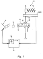
- Figure 1 shows a preferred embodiment of the invention Device 11 for monitoring the function of the Fluid control valves 12, by way of example a 3/2-way valve is shown.
- the valve 12 is with a actuated actuator or actuator coupled to the by way of example in the form of a single-acting pneumatic cylinder 13 is shown with return spring.
- actuated actuator or actuator coupled to the by way of example in the form of a single-acting pneumatic cylinder 13 is shown with return spring.
- return spring can be various types of actuators by means of the valve 12 are operated.
- the valve 12 has an electrical actuator 14 for valve actuation, the example in the form of an electromagnet is shown. In principle, other types are used by electrical actuators, for example Piezoelectric elements o. The like.
- the electromagnet is used according to preferred Embodiment for actuating a pilot valve 15, which in turn for pneumatic actuation of actual main valve 30 is used, for example such that a drive piston of the main valve 30 by means of Pressurized brought in different positions can be, so that thereby different valve channels with each other connected or can be separated from each other.
- a pilot valve 15 On the structure of the pilot and the main valve 15, 30th will not be discussed in detail below.
- the electric actuator 14 is provided with an operating status indicator 16 coupled, the example using an LED is shown.
- the operating status display 16 is used for display the current operating state of the electrical actuator 14, for example in the form that in a Excitation of the solenoid located in the electromagnet the LED lights up and thus indicates a functional status, while the LED is dark in the de-energized state of the solenoid remains.
- the device 11 for monitoring the operation of the valve 12 comprises an optical sensor 17, which by way of example with reference a photodiode is shown.
- the photodiode is the operating status indicator 16 faces and serves for optical Detecting a change in operating state of the electrical actuator 14.
- the optical sensor 17 is provided with a signal processing device 18 coupled in the following closer to be ceremoniesnden way to signal processing of the optical sensor 17 transmitted signals is used.
- the signal processing device 18 has an analysis unit 19 For example, a display on which different signals in Form of "peaks" can be displayed.
- a detection device 20 is provided which at a pressure hose connecting the valve outlet and the actuator 40 is attached.
- a detection device 20 includes the detection device 20 a mounting clamp 21, which can be attached to the pressure hose 40.
- the mounting clamp 21 in turn has two clamping legs 22a, 22 b, which can be clamped on the pressure hose 40, wherein on an clamping leg 22b, an acceleration sensor 23, which is a pressure change in the hose, with a Diameter change of the hose goes along, measures and in the form of an acceleration signal to the signal processing device 18 transmitted.
- the method according to the invention becomes exemplary described by a function monitoring of a 3/2-way valve, for fluid control of a single-acting Compressed air cylinder 13 is used.
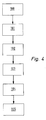
- step 100 represents the pressurizable piston chamber 24 of the air cylinder 13 by interconnection of the working connection "A" with the venting connection "R” vented.
- the solenoid of the electromagnet is in the unexposed Status.
- the LED is dark.
- the detection device 20, in particular their mounting clamp 21 is on Pressure hose 40 attached.
- the optical sensor 17 is, for example with a clip or plasticine in the area of the LED established.
- step 101 an operating state change is now made the solenoid is brought about, for example the solenoid of the electromagnet energized.
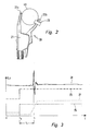
- the voltage curve of the magnet coil voltage 25 over the Time is shown in FIG. 3 by way of example with reference to the dashed line shown.
- the illumination of the LED which signals the operating state change of the electromagnet, is detected via the optical sensor 16 and converted into a signal, which is transmitted to the signal processing device 18 according to step 102.
- this signal is set as the start time t 0 .
- the acceleration sensor 23 measures one by the pressure change caused diameter change of the pressure hose 40th over a certain time window. In the concrete case will be the hose thus widen as a result of the pressure increase. It An acceleration signal is generated which is sent to the signal processing device 18 is transmitted, where, for example read on the analysis unit 19 in the form of a "peak" can be. According to step 104, the switching state is now of the valve 12 verified. If there is no such "peak", this is an indication that a malfunction of the Valve 12 is present, for example, that the valve 12 despite Excitation of the solenoid does not switch correctly. Come in "Peak” on, which is different from the noise floor, so is this is an indication that the valve 12 has switched.
Landscapes
- Engineering & Computer Science (AREA)
- General Engineering & Computer Science (AREA)
- Mechanical Engineering (AREA)
- Physics & Mathematics (AREA)
- Fluid Mechanics (AREA)
- Indication Of The Valve Opening Or Closing Status (AREA)
- Fluid-Pressure Circuits (AREA)
- Measuring Fluid Pressure (AREA)
Applications Claiming Priority (2)
| Application Number | Priority Date | Filing Date | Title |
|---|---|---|---|
| DE102004001915A DE102004001915B3 (de) | 2004-01-14 | 2004-01-14 | Verfahren und Vorrichtung zur Funktionsüberwachung bei Ventilen |
| DE102004001915 | 2004-01-14 |
Publications (2)
| Publication Number | Publication Date |
|---|---|
| EP1555472A1 true EP1555472A1 (fr) | 2005-07-20 |
| EP1555472B1 EP1555472B1 (fr) | 2007-12-19 |
Family
ID=34609534
Family Applications (1)
| Application Number | Title | Priority Date | Filing Date |
|---|---|---|---|
| EP04029305A Expired - Lifetime EP1555472B1 (fr) | 2004-01-14 | 2004-12-10 | Procédé et appareil pour la surveillance du fonctionnement de soupapes |
Country Status (3)
| Country | Link |
|---|---|
| EP (1) | EP1555472B1 (fr) |
| AT (1) | ATE381691T1 (fr) |
| DE (2) | DE102004001915B3 (fr) |
Cited By (4)
| Publication number | Priority date | Publication date | Assignee | Title |
|---|---|---|---|---|
| EP3501927A1 (fr) * | 2017-12-22 | 2019-06-26 | Goodrich Corporation | Systèmes et procédés de surveillance de l'état de santé d'une servovalve |
| WO2020035175A1 (fr) * | 2018-08-15 | 2020-02-20 | Fogtec Brandschutz Gmbh & Co. Kg | Procédé de surveillance de vannes |
| DE102019135575A1 (de) * | 2019-12-20 | 2021-06-24 | Bürkert Werke GmbH & Co. KG | Ventilinsel mit Diagnosemodul |
| DE102020114408A1 (de) | 2020-05-28 | 2021-12-02 | Bürkert Werke GmbH & Co. KG | Diagnoseverfahren für ein Prozessventil, Diagnosemodul und Prozessventil |
Families Citing this family (2)
| Publication number | Priority date | Publication date | Assignee | Title |
|---|---|---|---|---|
| DE102020201300B4 (de) | 2020-02-04 | 2022-06-02 | Festo Se & Co. Kg | Pneumatiksystem |
| DE102022213928A1 (de) * | 2022-12-19 | 2024-06-20 | Robert Bosch Gesellschaft mit beschränkter Haftung | Verfahren zum Betrieb einer Stelleinrichtung |
Citations (6)
| Publication number | Priority date | Publication date | Assignee | Title |
|---|---|---|---|---|
| EP0287299A2 (fr) * | 1987-04-13 | 1988-10-19 | Electric Power Research Institute, Inc | Système de contrôle et de diagnostic pour vanne à commande motorisée, sur base de microprocesseur |
| US4896101A (en) * | 1986-12-03 | 1990-01-23 | Cobb Harold R W | Method for monitoring, recording, and evaluating valve operating trends |
| US5202673A (en) * | 1989-09-19 | 1993-04-13 | Valve Security Systems, Inc. | Security method and apparatus |
| DE4439230A1 (de) * | 1994-11-03 | 1996-05-09 | Ingenieure Prof Sturm & Partne | Vorrichtung und Verfahren zur Zustandsbestimmung von Armaturen |
| EP0962685A1 (fr) * | 1998-06-03 | 1999-12-08 | Siemens-Elema AB | Système de soupapes |
| WO2002063192A1 (fr) * | 2001-02-07 | 2002-08-15 | Drallim Industries Limited | Appareil de test du fonctionnement d'une vanne de secours |
Family Cites Families (2)
| Publication number | Priority date | Publication date | Assignee | Title |
|---|---|---|---|---|
| US5826616A (en) * | 1996-11-19 | 1998-10-27 | Isi Norgren, Inc. | Valve spool position detector apparatus |
| US6523414B1 (en) * | 2001-04-16 | 2003-02-25 | Zevex, Inc. | Optical pressure monitoring system |
-
2004
- 2004-01-14 DE DE102004001915A patent/DE102004001915B3/de not_active Expired - Fee Related
- 2004-12-10 AT AT04029305T patent/ATE381691T1/de not_active IP Right Cessation
- 2004-12-10 DE DE502004005747T patent/DE502004005747D1/de not_active Expired - Lifetime
- 2004-12-10 EP EP04029305A patent/EP1555472B1/fr not_active Expired - Lifetime
Patent Citations (6)
| Publication number | Priority date | Publication date | Assignee | Title |
|---|---|---|---|---|
| US4896101A (en) * | 1986-12-03 | 1990-01-23 | Cobb Harold R W | Method for monitoring, recording, and evaluating valve operating trends |
| EP0287299A2 (fr) * | 1987-04-13 | 1988-10-19 | Electric Power Research Institute, Inc | Système de contrôle et de diagnostic pour vanne à commande motorisée, sur base de microprocesseur |
| US5202673A (en) * | 1989-09-19 | 1993-04-13 | Valve Security Systems, Inc. | Security method and apparatus |
| DE4439230A1 (de) * | 1994-11-03 | 1996-05-09 | Ingenieure Prof Sturm & Partne | Vorrichtung und Verfahren zur Zustandsbestimmung von Armaturen |
| EP0962685A1 (fr) * | 1998-06-03 | 1999-12-08 | Siemens-Elema AB | Système de soupapes |
| WO2002063192A1 (fr) * | 2001-02-07 | 2002-08-15 | Drallim Industries Limited | Appareil de test du fonctionnement d'une vanne de secours |
Cited By (7)
| Publication number | Priority date | Publication date | Assignee | Title |
|---|---|---|---|---|
| EP3501927A1 (fr) * | 2017-12-22 | 2019-06-26 | Goodrich Corporation | Systèmes et procédés de surveillance de l'état de santé d'une servovalve |
| US10442422B2 (en) | 2017-12-22 | 2019-10-15 | Goodrich Corporation | Systems and methods for monitoring a health status of a servo valve |
| WO2020035175A1 (fr) * | 2018-08-15 | 2020-02-20 | Fogtec Brandschutz Gmbh & Co. Kg | Procédé de surveillance de vannes |
| US12044332B2 (en) | 2018-08-15 | 2024-07-23 | Fogtec Brandschutz Gmbh | Method for monitoring fire-fighting system valve with sensor arranged outside the valve |
| DE102019135575A1 (de) * | 2019-12-20 | 2021-06-24 | Bürkert Werke GmbH & Co. KG | Ventilinsel mit Diagnosemodul |
| DE102020114408A1 (de) | 2020-05-28 | 2021-12-02 | Bürkert Werke GmbH & Co. KG | Diagnoseverfahren für ein Prozessventil, Diagnosemodul und Prozessventil |
| US12429396B2 (en) | 2020-05-28 | 2025-09-30 | Buerkert Werke Gmbh & Co. Kg | Diagnosis method for a process valve, diagnosis module and process valve |
Also Published As
| Publication number | Publication date |
|---|---|
| DE502004005747D1 (de) | 2008-01-31 |
| DE102004001915B3 (de) | 2005-11-03 |
| ATE381691T1 (de) | 2008-01-15 |
| EP1555472B1 (fr) | 2007-12-19 |
Similar Documents
| Publication | Publication Date | Title |
|---|---|---|
| DE60211325T2 (de) | Verfahren zur erfassung des gebrochenen ventilschafts | |
| DE102011075935B4 (de) | Ermittlung von Funktionszuständen eines elektromagnetischen Aktors | |
| EP0643814B1 (fr) | Procede et dispositif visant a verifier une garniture actionnee par un milieu | |
| DE102012016295B4 (de) | Vorrichtung und Verfahren zum Quantifizieren eines Leckagedurchflusses an einem Stellgerät | |
| DE10142790A1 (de) | Bremsdiagnose für Schienen- und Straßenfahrzeuge | |
| EP3546763B1 (fr) | Détection des états de maintenance de vannes | |
| DE102007016817A1 (de) | Verfahren zur Überprüfung der Funktionsfähigkeit eines Stellgerätes | |
| DE102005060862B3 (de) | Verfahren und Vorrichtung zur Beurteilung eines Dosiervorgangs | |
| DE102005004477A1 (de) | Verfahren zur Überprüfung einer Funktionsfähigkeit eines Stellgliedes, insbesondere für ein Sicherheitsventil | |
| EP1555472B1 (fr) | Procédé et appareil pour la surveillance du fonctionnement de soupapes | |
| EP1604120B1 (fr) | Procede pour l'essai de fonctionnement d'une soupape hydraulique | |
| US7210338B2 (en) | Valve testing device having integrated purge circuit and method of valve testing | |
| EP1338237B1 (fr) | Méthode et appareil pour tester l'ouverture des canaux d'un endoscope | |
| DE2544809C3 (de) | Einstecklehre zur Messung des Innendurchmessers einer Behälteröffnung | |
| EP3784937B1 (fr) | Procédé pour contrôler la fonction d'une vanne automatique, dispositif pour mettre en oeuvre un tel proccédé et vanne automatique comprenant un tel dispositif | |
| DE102016105881B4 (de) | Verfahren zur Ansteuerung und Überwachung eines Stellventils | |
| WO2011104039A1 (fr) | Procédé et dispositif pour déterminer la qualité des résultats de mesure d'un appareil de mesure de lumière diffusée | |
| JPH06294708A (ja) | 操作ペダルの耐久試験装置および耐久試験方法 | |
| DE102006059938B3 (de) | Verfahren zur Diagnose eines mit einer Hilfsenergie angetriebenen Stellorgans | |
| EP1086761B1 (fr) | Procédé et dispositif pour contrôler l'usure de pinces à sertissage | |
| EP2432982B1 (fr) | Procédé de mesure de la levée d'armature d'un injecteur de carburant | |
| DE3839504A1 (de) | Verfahren und vorrichtung zum messen der leckage eines mit einem gasfoermigen medium betriebenen geraetes | |
| DE102004012802B4 (de) | Verfahren zur Prüfung von Fehlern einer Antriebseinheit einer Spritzgiessmaschine | |
| DE69823687T2 (de) | Verfahren und vorrichtung zur regelung eines pneumatisch betätigten ventils | |
| DE102007042757A1 (de) | Verfahren und Vorrichtung zur Stellungsanzeige von hydraulisch betätigten Armaturen |
Legal Events
| Date | Code | Title | Description |
|---|---|---|---|
| PUAI | Public reference made under article 153(3) epc to a published international application that has entered the european phase |
Free format text: ORIGINAL CODE: 0009012 |
|
| AK | Designated contracting states |
Kind code of ref document: A1 Designated state(s): AT BE BG CH CY CZ DE DK EE ES FI FR GB GR HU IE IS IT LI LT LU MC NL PL PT RO SE SI SK TR |
|
| AX | Request for extension of the european patent |
Extension state: AL BA HR LV MK YU |
|
| 17P | Request for examination filed |
Effective date: 20050603 |
|
| AKX | Designation fees paid |
Designated state(s): AT BE BG CH CY CZ DE DK EE ES FI FR GB GR HU IE IS IT LI LT LU MC NL PL PT RO SE SI SK TR |
|
| GRAP | Despatch of communication of intention to grant a patent |
Free format text: ORIGINAL CODE: EPIDOSNIGR1 |
|
| GRAS | Grant fee paid |
Free format text: ORIGINAL CODE: EPIDOSNIGR3 |
|
| GRAA | (expected) grant |
Free format text: ORIGINAL CODE: 0009210 |
|
| AK | Designated contracting states |
Kind code of ref document: B1 Designated state(s): AT BE BG CH CY CZ DE DK EE ES FI FR GB GR HU IE IS IT LI LT LU MC NL PL PT RO SE SI SK TR |
|
| REG | Reference to a national code |
Ref country code: GB Ref legal event code: FG4D Free format text: NOT ENGLISH |
|
| REG | Reference to a national code |
Ref country code: IE Ref legal event code: FG4D Free format text: LANGUAGE OF EP DOCUMENT: GERMAN |
|
| REG | Reference to a national code |
Ref country code: CH Ref legal event code: EP |
|
| REF | Corresponds to: |
Ref document number: 502004005747 Country of ref document: DE Date of ref document: 20080131 Kind code of ref document: P |
|
| PG25 | Lapsed in a contracting state [announced via postgrant information from national office to epo] |
Ref country code: SE Free format text: LAPSE BECAUSE OF FAILURE TO SUBMIT A TRANSLATION OF THE DESCRIPTION OR TO PAY THE FEE WITHIN THE PRESCRIBED TIME-LIMIT Effective date: 20080319 |
|
| PG25 | Lapsed in a contracting state [announced via postgrant information from national office to epo] |
Ref country code: LT Free format text: LAPSE BECAUSE OF FAILURE TO SUBMIT A TRANSLATION OF THE DESCRIPTION OR TO PAY THE FEE WITHIN THE PRESCRIBED TIME-LIMIT Effective date: 20071219 Ref country code: PL Free format text: LAPSE BECAUSE OF FAILURE TO SUBMIT A TRANSLATION OF THE DESCRIPTION OR TO PAY THE FEE WITHIN THE PRESCRIBED TIME-LIMIT Effective date: 20071219 Ref country code: NL Free format text: LAPSE BECAUSE OF FAILURE TO SUBMIT A TRANSLATION OF THE DESCRIPTION OR TO PAY THE FEE WITHIN THE PRESCRIBED TIME-LIMIT Effective date: 20071219 Ref country code: FI Free format text: LAPSE BECAUSE OF FAILURE TO SUBMIT A TRANSLATION OF THE DESCRIPTION OR TO PAY THE FEE WITHIN THE PRESCRIBED TIME-LIMIT Effective date: 20071219 Ref country code: SI Free format text: LAPSE BECAUSE OF FAILURE TO SUBMIT A TRANSLATION OF THE DESCRIPTION OR TO PAY THE FEE WITHIN THE PRESCRIBED TIME-LIMIT Effective date: 20071219 |
|
| NLV1 | Nl: lapsed or annulled due to failure to fulfill the requirements of art. 29p and 29m of the patents act | ||
| GBV | Gb: ep patent (uk) treated as always having been void in accordance with gb section 77(7)/1977 [no translation filed] | ||
| PG25 | Lapsed in a contracting state [announced via postgrant information from national office to epo] |
Ref country code: ES Free format text: LAPSE BECAUSE OF FAILURE TO SUBMIT A TRANSLATION OF THE DESCRIPTION OR TO PAY THE FEE WITHIN THE PRESCRIBED TIME-LIMIT Effective date: 20080330 Ref country code: IS Free format text: LAPSE BECAUSE OF FAILURE TO SUBMIT A TRANSLATION OF THE DESCRIPTION OR TO PAY THE FEE WITHIN THE PRESCRIBED TIME-LIMIT Effective date: 20080419 Ref country code: CZ Free format text: LAPSE BECAUSE OF FAILURE TO SUBMIT A TRANSLATION OF THE DESCRIPTION OR TO PAY THE FEE WITHIN THE PRESCRIBED TIME-LIMIT Effective date: 20071219 |
|
| PG25 | Lapsed in a contracting state [announced via postgrant information from national office to epo] |
Ref country code: RO Free format text: LAPSE BECAUSE OF FAILURE TO SUBMIT A TRANSLATION OF THE DESCRIPTION OR TO PAY THE FEE WITHIN THE PRESCRIBED TIME-LIMIT Effective date: 20071219 Ref country code: SK Free format text: LAPSE BECAUSE OF FAILURE TO SUBMIT A TRANSLATION OF THE DESCRIPTION OR TO PAY THE FEE WITHIN THE PRESCRIBED TIME-LIMIT Effective date: 20071219 |
|
| PG25 | Lapsed in a contracting state [announced via postgrant information from national office to epo] |
Ref country code: PT Free format text: LAPSE BECAUSE OF FAILURE TO SUBMIT A TRANSLATION OF THE DESCRIPTION OR TO PAY THE FEE WITHIN THE PRESCRIBED TIME-LIMIT Effective date: 20080519 |
|
| REG | Reference to a national code |
Ref country code: IE Ref legal event code: FD4D |
|
| EN | Fr: translation not filed | ||
| PLBE | No opposition filed within time limit |
Free format text: ORIGINAL CODE: 0009261 |
|
| STAA | Information on the status of an ep patent application or granted ep patent |
Free format text: STATUS: NO OPPOSITION FILED WITHIN TIME LIMIT |
|
| PG25 | Lapsed in a contracting state [announced via postgrant information from national office to epo] |
Ref country code: DK Free format text: LAPSE BECAUSE OF FAILURE TO SUBMIT A TRANSLATION OF THE DESCRIPTION OR TO PAY THE FEE WITHIN THE PRESCRIBED TIME-LIMIT Effective date: 20071219 Ref country code: IE Free format text: LAPSE BECAUSE OF FAILURE TO SUBMIT A TRANSLATION OF THE DESCRIPTION OR TO PAY THE FEE WITHIN THE PRESCRIBED TIME-LIMIT Effective date: 20071219 |
|
| 26N | No opposition filed |
Effective date: 20080922 |
|
| PG25 | Lapsed in a contracting state [announced via postgrant information from national office to epo] |
Ref country code: GB Free format text: LAPSE BECAUSE OF FAILURE TO SUBMIT A TRANSLATION OF THE DESCRIPTION OR TO PAY THE FEE WITHIN THE PRESCRIBED TIME-LIMIT Effective date: 20071219 |
|
| PG25 | Lapsed in a contracting state [announced via postgrant information from national office to epo] |
Ref country code: GR Free format text: LAPSE BECAUSE OF FAILURE TO SUBMIT A TRANSLATION OF THE DESCRIPTION OR TO PAY THE FEE WITHIN THE PRESCRIBED TIME-LIMIT Effective date: 20080320 |
|
| PG25 | Lapsed in a contracting state [announced via postgrant information from national office to epo] |
Ref country code: EE Free format text: LAPSE BECAUSE OF FAILURE TO SUBMIT A TRANSLATION OF THE DESCRIPTION OR TO PAY THE FEE WITHIN THE PRESCRIBED TIME-LIMIT Effective date: 20071219 Ref country code: FR Free format text: LAPSE BECAUSE OF FAILURE TO SUBMIT A TRANSLATION OF THE DESCRIPTION OR TO PAY THE FEE WITHIN THE PRESCRIBED TIME-LIMIT Effective date: 20081010 Ref country code: BG Free format text: LAPSE BECAUSE OF FAILURE TO SUBMIT A TRANSLATION OF THE DESCRIPTION OR TO PAY THE FEE WITHIN THE PRESCRIBED TIME-LIMIT Effective date: 20080319 |
|
| BERE | Be: lapsed |
Owner name: FESTO A.G. & CO. Effective date: 20081231 |
|
| PG25 | Lapsed in a contracting state [announced via postgrant information from national office to epo] |
Ref country code: CY Free format text: LAPSE BECAUSE OF FAILURE TO SUBMIT A TRANSLATION OF THE DESCRIPTION OR TO PAY THE FEE WITHIN THE PRESCRIBED TIME-LIMIT Effective date: 20071219 Ref country code: MC Free format text: LAPSE BECAUSE OF NON-PAYMENT OF DUE FEES Effective date: 20081231 |
|
| REG | Reference to a national code |
Ref country code: CH Ref legal event code: PL |
|
| PG25 | Lapsed in a contracting state [announced via postgrant information from national office to epo] |
Ref country code: BE Free format text: LAPSE BECAUSE OF NON-PAYMENT OF DUE FEES Effective date: 20081231 |
|
| PG25 | Lapsed in a contracting state [announced via postgrant information from national office to epo] |
Ref country code: LI Free format text: LAPSE BECAUSE OF NON-PAYMENT OF DUE FEES Effective date: 20081231 Ref country code: CH Free format text: LAPSE BECAUSE OF NON-PAYMENT OF DUE FEES Effective date: 20081231 |
|
| PG25 | Lapsed in a contracting state [announced via postgrant information from national office to epo] |
Ref country code: AT Free format text: LAPSE BECAUSE OF NON-PAYMENT OF DUE FEES Effective date: 20081210 |
|
| PG25 | Lapsed in a contracting state [announced via postgrant information from national office to epo] |
Ref country code: LU Free format text: LAPSE BECAUSE OF NON-PAYMENT OF DUE FEES Effective date: 20081210 Ref country code: HU Free format text: LAPSE BECAUSE OF FAILURE TO SUBMIT A TRANSLATION OF THE DESCRIPTION OR TO PAY THE FEE WITHIN THE PRESCRIBED TIME-LIMIT Effective date: 20080620 |
|
| PG25 | Lapsed in a contracting state [announced via postgrant information from national office to epo] |
Ref country code: TR Free format text: LAPSE BECAUSE OF FAILURE TO SUBMIT A TRANSLATION OF THE DESCRIPTION OR TO PAY THE FEE WITHIN THE PRESCRIBED TIME-LIMIT Effective date: 20071219 |
|
| PG25 | Lapsed in a contracting state [announced via postgrant information from national office to epo] |
Ref country code: IT Free format text: LAPSE BECAUSE OF NON-PAYMENT OF DUE FEES Effective date: 20081231 |
|
| PGFP | Annual fee paid to national office [announced via postgrant information from national office to epo] |
Ref country code: DE Payment date: 20121108 Year of fee payment: 9 |
|
| REG | Reference to a national code |
Ref country code: DE Ref legal event code: R119 Ref document number: 502004005747 Country of ref document: DE |
|
| REG | Reference to a national code |
Ref country code: DE Ref legal event code: R119 Ref document number: 502004005747 Country of ref document: DE Effective date: 20140701 |
|
| PG25 | Lapsed in a contracting state [announced via postgrant information from national office to epo] |
Ref country code: DE Free format text: LAPSE BECAUSE OF NON-PAYMENT OF DUE FEES Effective date: 20140701 |