EP1555578A2 - Dispositif de formation d'images dans lequel des feuilles à onglets sont utiliseés - Google Patents
Dispositif de formation d'images dans lequel des feuilles à onglets sont utiliseés Download PDFInfo
- Publication number
- EP1555578A2 EP1555578A2 EP04026183A EP04026183A EP1555578A2 EP 1555578 A2 EP1555578 A2 EP 1555578A2 EP 04026183 A EP04026183 A EP 04026183A EP 04026183 A EP04026183 A EP 04026183A EP 1555578 A2 EP1555578 A2 EP 1555578A2
- Authority
- EP
- European Patent Office
- Prior art keywords
- tab
- sheet
- image
- section
- image forming
- Prior art date
- Legal status (The legal status is an assumption and is not a legal conclusion. Google has not performed a legal analysis and makes no representation as to the accuracy of the status listed.)
- Withdrawn
Links
Images







Classifications
-
- G—PHYSICS
- G03—PHOTOGRAPHY; CINEMATOGRAPHY; ANALOGOUS TECHNIQUES USING WAVES OTHER THAN OPTICAL WAVES; ELECTROGRAPHY; HOLOGRAPHY
- G03G—ELECTROGRAPHY; ELECTROPHOTOGRAPHY; MAGNETOGRAPHY
- G03G15/00—Apparatus for electrographic processes using a charge pattern
- G03G15/65—Apparatus which relate to the handling of copy material
- G03G15/6588—Apparatus which relate to the handling of copy material characterised by the copy material, e.g. postcards, large copies, multi-layered materials, coloured sheet material
- G03G15/6594—Apparatus which relate to the handling of copy material characterised by the copy material, e.g. postcards, large copies, multi-layered materials, coloured sheet material characterised by the format or the thickness, e.g. endless forms
-
- G—PHYSICS
- G03—PHOTOGRAPHY; CINEMATOGRAPHY; ANALOGOUS TECHNIQUES USING WAVES OTHER THAN OPTICAL WAVES; ELECTROGRAPHY; HOLOGRAPHY
- G03G—ELECTROGRAPHY; ELECTROPHOTOGRAPHY; MAGNETOGRAPHY
- G03G2215/00—Apparatus for electrophotographic processes
- G03G2215/00362—Apparatus for electrophotographic processes relating to the copy medium handling
- G03G2215/00443—Copy medium
- G03G2215/00523—Other special types, e.g. tabbed
Definitions
- the present invention relates to an image forming apparatus such as copying machines or printers, particularly to an image forming apparatus that is able to print on sheets with tabs.
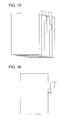
- Fig. 15 is an explanatory drawing showing sheets with tabs. Seven sheets of paper are shown in this drawing, and the third sheet from the top (X in Fig. 15) and the fifth sheet from the top (Y in Fig. 15) are "sheets with tabs.”
- the portion x protruding from the third sheet from the top is the tab
- the portion y protruding from the fifth sheet from the top is the tab
- L stands for the tab length
- W stands for the tab width.
- positions of the tabs x and y differ from each other in terms of the length-wise direction of the sheets, these positions are the specified tab positions.
- Fig. 17(a) through Fig. 17(d) are explanatory drawings each showing an example tab type.
- Tabs shown in Fig. 17(a) have the same width but different lengths (Type A), and the side of the sheet provided with a tab is divided into 3 (3 tabs). In other words, the division number in this case is 3.
- Tabs shown in Fig. 17(b) have the same width but different lengths (Type A), and the side of the sheet provided with a tab is divided into 4 (4 tabs). In other words, the division number in this case is 4.
- Tabs shown in Fig. 17(c) have the same width and length, but the positions in which they are provided (tab position) differ from each other (Type B), and the side of the sheet provided with a tab is divided into 3 (3 tabs). In other words, the division number in this case is 3.
- Tabs shown in Fig. 17(d) have the same width and length, but the positions that they are provided (tab position) differ from each other (Type B), and the side of the sheet provided with a tab is divided into 4 (4 tabs). In other words, the division number in this case is 4.
- sheets had to be set in the paper feed cassette with the tabs at correct positions so that the formed images on the tabs would not run off the edge. Furthermore, the finished images could only be checked after the images were actually formed on the tabs.
- sheets with tabs were usually inserted between other sheets of paper, and their tabs thus had to be arranged in the correct order for insertion when they were set in the paper feed cassette. In other words, when the order of the tabs was incorrectly arranged, sheets with tabs at the desired positions were not appropriately inserted.
- Patent Document 1 representing Official Gazette of Japanese Patent Tokkaihei 8-245003.
- sheets with tabs and regular sheets are fed and conveyed with intervals in between, and these intervals are calculated based on the order arrangement of sheets with tabs and sheets without tabs.
- this method has a problem in that, when a type of sheets with tabs that is not planned to be fed is actually fed, then image forming apparatuses are not able to appropriately conduct paper conveyance or image forming operation.
- image processing apparatuses in fact provided some extra room to be added to the already provided intervals before and after a sheet with a tab. For this reason, image forming apparatuses were not able to maximize its capability (productivity (the number of sheets that went through the apparatus per unit time)) when they used sheets with tabs.
- the first object of the present invention is to provide an image forming apparatus capable of ensuring the maximum productivity when a sheet with a tab is used.
- the second object of the present invention is to provide an image forming apparatus capable of preventing an unintended image from being formed or an image from being formed out of the sheet when a sheet with a tab is used.
- the third object of the present invention is to provide an image forming apparatus ensuring an intended image to be formed when a sheet with a tab is used.
- the inclination of the sheet is calculated according to the results of detection by a plurality of detectors of the tab detecting section, and the information on the image to be formed by the image forming section is corrected in response to the calculated inclination of the sheet.
- Control is provided in such a way that no inclination occurs to the sheet for the image to be formed thereon.
- FIG. 2 a mechanical configuration within the overall configuration of an apparatus, to which an image forming device of the embodiment is applied, is described.
- a mechanical configuration of the image forming apparatus is described with reference to Fig. 2.
- a copying machine that scans images from hard copies and conducts image formation is used as a specific example of the present embodiment.
- an image forming apparatus is used for the specific example as a copying machine employing an electrophotographic method.
- numeral 30 denotes a feeding section that feeds stacked sheets of paper
- numeral 40 denotes a writing section that generates light beams for exposure in accordance with image data
- numeral 50 denotes an image forming section that uses the electrostatic printing method to record image data onto recording medium p (generally referred to as recording paper or transfer paper, but referred to as a sheet in this document)
- numeral 60 denotes a conveying and driving means for conveying sheets
- numeral 70 denotes a finisher section that conducts post-processing such as sorting.
- numeral 81 denotes a tab detection sensor composed of a plurality of light receiving elements and light emitting elements arranged in the main scanning direction (direction perpendicular to Fig. 2, and perpendicular to conveyance direction) that detects tab positions, tab widths, tab types, and tab lengths.
- the sheet p is sent out from one of paper feed trays 30a to 30c, in which the sheet p is loaded, by one of the first paper feed rollers 31a to 31c, and is fed to the image forming section 50.
- paper feed trays 30a to 30c and the first paper feed rollers 31a to 31c constitute a paper feed means to feed the sheet p.
- three stories of sheet feed trays as plural sheet feed trays are provided as an example.
- the invention is not limited to the example.
- the sheet p to be fed to the image forming section 50 becomes synchronized with formation of a toner image on the photoreceptor drum 51 by a second paper feed roller (registration roller) 32 near the inlet of the section so that a distance between adjoining sheets is constant (Ti), and then comes close to a photoreceptor drum 51 as an image bearing body.
- the leading edge of the sheet P is detected by the leading edge detection sensor 82, and the irradiation timing of the laser beam, which will be described later, in the photoreceptor drum 51 is determined in response to the result of this detection.
- Image data is inputted to the writing section 40 by the recorded image processor, and a laser diode within the writing section 40 applies a laser beam to the photoreceptor drum 51 in accordance with the result of detection of the sheet P by the leading edge detection sensor 82 to form an electrostatic latent image.
- An image developing section 53 develops the electrostatic latent image, and a toner image is formed on the photoreceptor drum 51.
- the toner image is then transferred onto the sheet p by a transfer section 54 underneath the photoreceptor drum 51.
- the sheet p, pressed to the photoreceptor drum 51 by pressure, is then separated from the drum by a separation section 55.
- the sheet p separated from the photoreceptor drum 51 enters a fuser 59 via a conveyance mechanism, and then the toner image becomes fixed by heat and pressure. An image thus becomes formed onto the sheet p.
- the sheet p with fused toner image is conveyed into the lower part via a guide 61 and then enters a reverse conveyer section 63.
- the sheet p in the reverse conveyer section 63 is again conveyed by reverse rollers and enters again the image forming section 50 via a reverse conveyance route 64.
- the toner on the photoreceptor drum 51 is removed by a cleaner 56 and then the drum is electrically charged by a charger 52 to prepare for the next image forming session.
- the other side of the sheet p (the side with no image formed yet) becomes loaded into the image forming section 50, and an image is formed.
- the sheet p separated from the photoreceptor drum 51 by the separation section 55 again enters the fuser 59, via the conveyance mechanism 58, to be fixed with the image.
- the sheet p with images formed on both sides or the sheet p with images formed on one side then is sent to a finisher section 70.
- the finisher section 70 there are a designated tray 71 and an undesignated tray 72.
- the sheet is ejected to one of the trays depending on the result of detection by the tab detection sensor.
- the second rollers 32 and sections that convey the sheet after it is through the roller constitute a conveying and driving means 60, and in the present embodiment, specified control is executed to conveying operations by the conveying and driving means 60.
- both sheets without tabs and with tabs are fed by the feeding section 30, and before transferring, the tab detection sensor 81 determines whether the sheets have tabs or not, and also detects tab positions and tab directions for the fed sheets (without tabs or with tabs). Then images are formed by the image forming section 50 onto the sheets with tabs, including the tab as a target area for image formation.
- the tab detection sensor 81 be capable of detection prior to image formation, and is further preferred that the tab detection sensor 81 be capable of detection on each surface at the time of both-side image formation.
- a tab detection sensor 81 is arranged along the path to be followed in the case of reverse-side image formation.
- the finisher section 70 allows the sheet to be ejected into a tray other than the specified tray for normal use. This minimizes the confusion on the part of the user.
- Fig. 1 is a block drawing showing a detailed electric configuration within the image forming apparatus of the first embodiment.
- Numeral 100 denotes a type of an image forming apparatus that forms and outputs images onto sheets of paper including sheets with tabs.
- This image forming apparatus 100 is provided with: an overall control section 101 that executes controls that are related to sheets with tabs, in addition to controls for the overall apparatus; an operation and display section 110 that is used for making various operational inputs and for displaying apparatus status; an image processing section 120 that executes image processing for sheets with tabs, in addition to regular image processing; an image memory 130 that expands or holds image data to be processed by the image processing section 120 or other various types of data; and a print engine 140 that forms image data onto sheets.
- an overall control section 101 that executes controls that are related to sheets with tabs, in addition to controls for the overall apparatus
- an operation and display section 110 that is used for making various operational inputs and for displaying apparatus status
- an image processing section 120 that executes image processing for sheets with tabs, in addition to regular image processing
- an image memory 130 that expands or holds image data to be processed by the image processing section 120 or other various types of data
- a print engine 140 that forms image data onto sheets.
- the apparatus can be equipped with the finisher section 70 that sorts sheets with formed images.
- the overall control section 101 constitutes a control means for controlling image formation in the present embodiment.
- the operation and display section 110 is provided with: an operation section 111 as an information input section for receiving inputs of information on the tab of the tab-containing sheet (including the tab type, tab position (tab position in the sheet conveyance direction, tab position in the direction orthogonal to sheet conveyance direction)), tab width, tab length, number of divided tabs, tab direction (tab located at the leading edge or trailing edge in the sheet conveyance direction, or on the side orthogonal to the sheet conveyance direction), the leading edge of the sheet in the sheet conveyance direction when the tab is located at the leading edge (front end of the sheet) in the sheet conveyance direction, the trailing edge of the sheet in the sheet conveyance direction when the tab is located at the leading edge (rear end of the sheet) in the sheet conveyance direction, page to be inserted, presence or absence of tab image formation (image formed side), and contents of images to be formed on tab); and a display section 112 for displaying various types of information and statuses.
- an operation section 111 as an information input section for receiving inputs of information on the tab
- the display section 112 and a buzzer and a warning lamp which are not shown in the drawing, constitute a notification means for making notifications by outputting alarm displays, alarm sounds, alarm voice messages, or simultaneous output of any combinations of the above.
- the print engine 140 contains: a writing section 40 (Fig. 2) for writing in response to the image data processed by the image processing section 120; a tab detection sensor 81 as a tab detector; a leading edge detection sensor 82 (Fig. 2) for detecting the leading edge of the sheet during conveyance, for synchronizing the sheet conveyance timing with the image formation timing; and a drive section 141 for feeding and conveying various types of sheets.
- a writing section 40 for writing in response to the image data processed by the image processing section 120
- a tab detection sensor 81 as a tab detector
- a leading edge detection sensor 82 Fig. 2 for detecting the leading edge of the sheet during conveyance, for synchronizing the sheet conveyance timing with the image formation timing
- a drive section 141 for feeding and conveying various types of sheets.
- the tab detection sensor 81 checks whether the sheet has a tab or not. If it is a tab-containing sheet, the tab detection sensor 81 checks the tab type, tab position (tab position in the sheet conveyance direction, tab position in the direction orthogonal to the sheet conveyance direction), tab width, tab length, the number of divided tabs, tab direction (tab located at the leading edge or trailing edge in the sheet conveyance direction, or on the side orthogonal to the sheet conveyance direction), the leading edge of the sheet in the sheet conveyance direction when the tab is located at the leading edge (front end of the sheet) in the sheet conveyance direction, the trailing edge of the sheet in the sheet conveyance direction when the tab is located at the leading edge (rear end of the sheet) in the sheet conveyance direction, page to be inserted, presence or absence of tab image formation (image formed side), and contents of images to be formed on tab).
- This image forming apparatus 100 can be applied to various types of apparatus such as copying machines, facsimiles, and printers.
- the print engine 140 can be of an electrophotographic type that uses laser beams, an LED print head type, an ink jet type, a thermal type, or a die sublimation type.
- control section 101 controls or operations by sub-routines of the image formation control programs (computer program) will be simply referred to as control of the overall control section 101.
- the control section 101 displays a screen on the display section 112 to accept inputs of various types of information regarding the sheets with tabs, and receives various types of tab information as "Information on Tabs on Sheets with Tabs" from the user (S2), wherein this information includes the tab type, tab position (tab position in the sheet conveyance direction, tab position in the direction orthogonal to the sheet conveyance direction), tab width, tab length, the number of divided tabs, tab direction (tab located at the leading edge or trailing edge in the sheet conveyance direction, or on the side orthogonal to the sheet conveyance direction), the leading edge of the sheet in the sheet conveyance direction when the tab is located at the leading edge (front end of the sheet) in the sheet conveyance direction, the trailing edge of the sheet in the sheet conveyance direction when the tab is located at the leading edge (rear end of the sheet) in the sheet conveyance direction, page to be inserted, presence or absence of tab image formation (image formed side (single side-front side, single side-back side or both sides)).
- the control section 101 can be arranged in such a configuration that a communication means such as a network (not illustrated), a linkage means or a memory card is used to get various types of information on the tab-containing sheet, including the tab type, tab position (tab position in the sheet conveyance direction, tab position in the direction orthogonal to the sheet conveyance direction), tab width, tab length, the number of divided tabs, tab direction (tab located at the leading edge or trailing edge in the sheet conveyance direction, or on the side orthogonal to the sheet conveyance direction), the leading edge of the sheet in the sheet conveyance direction when the tab is located at the leading edge (front end of the sheet) in the sheet conveyance direction, the trailing edge of the sheet in the sheet conveyance direction when the tab is located at the leading edge (rear end of the sheet) in the sheet conveyance direction, page to be inserted, presence or absence of tab image formation (image formed side (single side-front side, single side-back side, or both sides)).
- a communication means such as a network (not illustrated
- the control section 101 receives via the operation section 111 inputs of letters and characters or symbols to be formed onto the tabs (S4).
- control section 101 When letters and characters or symbols to be formed onto the aforementioned tabs are accepted, the control section 101 creates a preview of how images will be formed onto the tabs and then displays it in the display section 112 (S5).
- control section 101 returns to the tab information input step (S2) so that various settings of the sheets with the tabs and also inputs of letters and characters and symbols to be formed onto the tabs will be made again.
- control section 101 If the user checks and approves the preview screen (Y in S6), the control section 101 enters copy start standby mode (S7). If the copy start key on the operation section 111 is pressed in this state, the control section 101 starts the image formation process based on the conditions set for the supplied image data (Y in S7).
- control section 101 feeds the sheets from the paper feed trays 30a to 30c (S8). Note that when images must be formed onto sheets without tabs for particular pages, sheets are fed from the feeding section in which sheets without tabs are stacked, and when images must be formed onto sheets with tabs for particular pages, sheets are fed from the feeding section in which sheets with tabs are stacked.
- the tab detection sensor 81 located at the position before image formation determines whether or not the fed sheets of paper have a tab or not and also detects position and direction of tabs on fed sheets with tabs (S9). Incidentally, specific example regarding tab detection will be explained later.
- Figs. 4(a) and 4(b) are explanatory drawings showing operation patterns of the tab detection sensor 81.
- the tab detection sensor 81 composed of a plurality of sensors A to J. It may is composed of a larger number of sensors in actual practice.
- drawings show examples of two cases: the case in which the tab on a sheet with a tab is located at the leading edge of the sheet (upstream) (Fig. 4(a)), and the case in which the tab on a sheet with a tab is located at the trailing edge of the sheet (downstream) (Fig. 4(b)).
- the sensor detects tab lengths, tab widths, tab positions (see Figs. 16 and 17), and tab directions (whether the tab is located upstream or downstream) based on timing differentials between the tab and the other part (non-tab portion) for passing the plurality of sensors.
- tab directions whether the tab is located upstream or downstream
- the sheet is conveyed from left to right, it means that the tab is located at the trailing edge of the sheet, and if the sheet is conveyed from right to left, it means that the tab is located at the leading edge of the sheet.
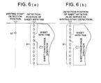
- Figs. 4(a) and 4(b), Figs. 5(a) through 5(d), and Figs. 6(a) and 6(b) show specific examples when a tab is present in the direction orthogonal to the sheet conveyance direction.
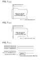
- Figs. 7(a) through 7(c) the present embodiment is also applicable to the case where a tab is present in the direction parallel to the sheet conveyance direction, i.e. where the sheet is fed in the longitudinal direction.
- a tab may be present on the right in the sheet conveyance direction, as shown in Fig. 7(a), or on the left, as shown in Fig. 7(b).
- the right or left position is determined, depending on whether the portion corresponding to the tab position range occurs on the right of the sheet or on the left, according to the results of detection by the tab detection sensors 81 (tab detection sensors 81A through 81N + 1) in the state shown in Fig. 7(b). Further, the tab position and tab length (tab position range) are calculated by measuring the signal range by a timer.
- a fed sheet is judged as being a sheet without a tab ("sheet without tab" in S11) as a result of detection of tab position and direction for a sheet with a tab (S9), then normal conveyance control is executed (S13).
- the normal conveyance control refers to conveyance control in which the distance between the position of the upstream leading edge in the sheet conveyance direction of a preceding sheet and the position of the upstream leading edge in the sheet conveyance direction of a succeeding sheet is kept constant.
- image write timing is calculated (S10).
- conveyance control specific to the present embodiment is performed (S12). The specific description of calculating the image write timing is given in the description of the second embodiment.
- conveyance control is provided in such a way as to keep constant the interval between the trailing edge of a tab-containing sheet and the leading edge of the succeeding sheet. If the tab is located at the leading edge of the sheet, conveyance control is provided in such a way as to keep constant the interval between the trailing edge of the sheet preceding the tab-containing sheet and the leading edge of the tab-containing sheet.
- Fig. 12(a) through 12(h) are explanatory diagrams showing the position of the tabs of two sheets fed in the sheet conveyance direction, and the concept of control of intervals between sheets.
- #1 (sheet #1) denotes a sheet being fed ahead of the other (a preceding sheet), and #2 (sheet #2) indicates a sheet succeeding the #1 (a succeeding sheet).
- Td shows the interval between sheets, Ti the interval between two sheets being fed where both of them have no tab, and ⁇ ts the length of the tab at the leading edge of the sheet #2 in the conveyance direction ⁇ te the trailing edge of the sheet #1 in the conveyance direction.
- conveyance control is provided in such a way that the interval Td between the sheets #1 and #2 will be Ti, as shown in Fig. 12(a).
- conveyance control is provided in such a way that the interval Td between the sheets #1 and #2 will be Ti, as shown in Fig. 12 (b).
- conveyance control is provided in such a way that the interval Td between the sheets #1 and #2 will be Ti + ⁇ ts, as shown in Figs. 12(d) and 12(e).
- conveyance control is provided in such a way that the interval Td between the sheets #1 and #2 will be Ti + ⁇ te, as shown in Fig. 12(f).
- the tab detection sensor 81 determines whether a tab is located at the leading edge of the sheet #2 (Y in S12-1). If it has been determined that a tab is located at the leading edge of the sheet #2 (Y in S12-1), the length of the tab of the sheet #2 in the sheet conveyance direction is measured by the tab detection sensor 81. The result of the measurement is assumed as the tab size dt1 at the leading edge (S12-2). If it has been determined that there is no at the leading edge of the sheet #2 (N in S12-1), the tab size dt1 at the leading edge is assumed as 0 (S12-3).
- Such conveyance control removes the possibility of collision between a tab-containing sheet and a sheet preceding or succeeding the same, even when sheets are conveyed by reducing the interval between sheets in order to improve productivity, and eliminates the need of providing a margin of safety in sheet-to-sheet intervals.
- the control section 101 activates an alarm (S21) to notify that the sheet with a tab that has been specified does not agree with the sheet with a tab that has actually been fed, and temporarily stops the operation of the image forming apparatus (S22).
- the disagreement warning alarm can be the alarm display on the display section 112 by the control 101, outputs of buzzer sounds not shown in the drawing, outputs of voice messages also not shown in the drawing, or simultaneous use of the above.
- control section 101 refers to various types of information, including the content of images to be formed inputted by the operation section 111 and the result of detection by the tab detection sensor 81, and the image processing section 120 processes images so that the writing section 40 forms images onto the tab part of a sheet with a tab. Also in the present embodiment, the images to be formed onto the tab part are displayed in the display section 112 beforehand. For the above reasons, accurate image formation onto the sheet including the tab part can be carried out.
- the tab detection in the aforementioned operation and sheet conveyance control by the control section 101 in response to this tab detection are preferred to be carried out as described in any one of the following (a) through (p).
- the tab information input and tab detection in the aforementioned operation, and image formation operation control in response to this information input and tab detection are preferred to be carried out as described in any one of the following (A) through (L).
- the aforementioned configuration and operation provide an image forming apparatus that allows an image to be formed on one side or both sides, including the tab of a tab-containing sheet, using various types of tab-containing sheets, without complicated setting operations, wherein a tab-containing sheet at a desired position can be inserted into a desired page position.
- the aforementioned configuration and operation ensure the maximum use of productivity when an image is to be formed on one side or both sides, including the tab of a tab-containing sheet, using various types of tab-containing sheets, without complicated setting operations.
- Figs. 8(a) to 8(d) are explanatory drawings that illustrate operations in the second embodiment of the present invention.
- Fig. 9 is a flowchart illustrating operation in the second embodiment of the present invention, and the operations are basically the same as that of the flowchart in Fig. 3. The redundant explanations on the common items will be omitted, and only differences will be described.
- control section 101 is able to detect based on the result of detection provided by the tab detection sensor 81 as shown in Fig. 8(b) that, as a result of tab positions and directions detection (S49), the sheet with a tab fed by the feeding section 30 is inclined as shown in Fig. 8(a).
- control section 101 is able to detect based on the result of detection provided by the tab detection sensor 81 as shown in Fig. 8(d) that, as a result of tab positions and directions detection (S49 in Fig. 9), the sheet with a tab fed by the feeding section 30 is inclined as shown in Fig. 8(c).
- control section 101 processes calculation for correction of image write timing, based on the tab position detected by the tab detection sensor 81 and the result of detecting the size (S50 in Fig. 9), and calculates the inclination angle of the sheet by referencing the result of detecting the sheet skew in the next step, whereby the image to be formed is rotated on the image memory in response to the inclination angle (S51).
- the "conveyance control for keeping constant the interval between the trailing edge of a sheet and the leading edge of the succeeding sheet" in S53 of Fig. 9 denotes conveyance control for keeping constant the interval between the trailing edge of the tab-containing sheet and the leading edge of the succeeding sheet, if the tab is located at the trailing edge of the sheet.
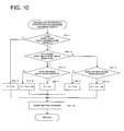
- Fig. 10 shows the details of the procedures of image write timing control (S50 in Fig. 9) in the aforementioned flowchart.
- Image write timing control is represented in the function block diagrams of the Figs. 11 (a) and 11 (b).
- the control section 101 having received the result of detection by the tab detection sensor 81 corrects the preadjusted image write timing data Tvd, according to the correction data ⁇ ts of the tab size calculated from the result of tab detection. Then the corrected image write timing Tv is set on the count setting register of the image write start counter 101c.
- the image write start counter 101c uses the detection signal of the leading edge detection sensor 82 as a trigger to determine the image write start timing.
- the image write start signal is then transmitted to the image processing section 120, whereby image writing starts.
- the control section 101 in response to the result of detection by the tab detection sensor 81 sets the corrected image write timing data Tv on the count setting register of the image write start counter 101c, as described above with reference to Fig. 11(b).
- the pseudo-leading edge signal generation circuit 101a Based on the detection signal of the leading edge detection sensor 82, the pseudo-leading edge signal generation circuit 101a generates a pseudo-leading edge signal, which is delayed a predetermined time by the signal delay circuit 101b.
- the delayed pseudo-leading edge signal is used as a trigger to cause the image write start counter 101c to count up to the timing data Tv.
- the image write start timing is determined and image write start timing signal is transmitted to the image processing section 120, whereby image writing starts.
- the time delayed by the signal delay circuit 101b is equivalent to the time required for the sheet to be conveyed over the distance between the position of the tab detection sensor 81 and the position where the leading edge detection sensor 82 is assumed to be located.
- the control section 101 determines that the tab is located at the position of the leading edge detection sensor 82 (image write start sensor) (Y in S10-2). If no tab is found at the position of the leading edge detection sensor 82 (image write start sensor) (N in S10-2), a check is made to see if an image is formed (printed) on the tab or not (S10-4).
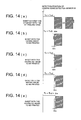
- Tv Tvd is assumed, as shown in Fig. 14(c), and the control section 101 does not correct the tab portion (S10-8).
- the control section 101 corrects the tab portion (S10-6). To put it another way, in this case, Tv is corrected by the tab length ⁇ ts in the sheet conveyance direction, as shown in Fig. 14(e), and the timing data Tv (data to be set on the count setting register of the image write start counter 101c) is set to Tvd + ⁇ ts.
- the signal formed by delaying of the pseudo-leading edge signal generated as a result of detection by the tab detection sensor 81 should be used on behalf of the result of detecting the leading edge of the sheet.
- the image write start timing calculation and control in conformity to the tab in the aforementioned operation are preferred to be carried out as described in any one of the following (1) through (7).
- a modification is possible such as in the case in which if a sheet with a tab having a tab larger than the specified tab is fed but image forming operation to the tab is still executable with no problems, image formation operation will continue although a warning is issued.
- image formation operation it is desirable that image formation operation be stopped whether there is a possibility of images being formed outside the tab or image formation is definitely impossible.
- control section 101 first issues an alarm (S21 in Fig. 3, and S23 in Fig. 10) to notify that the sheet with a tab that is specified does not agree with the actually fed sheet with a tab, and temporarily stops the operation of the image forming apparatus (S22 in Fig. 3, and S23 in Fig. 10), control can be executed so as to stop the image forming operation without issuing an alarm.
- an alarm S21 in Fig. 3, and S23 in Fig. 10
Landscapes
- Physics & Mathematics (AREA)
- General Physics & Mathematics (AREA)
- Controlling Sheets Or Webs (AREA)
- Sheets, Magazines, And Separation Thereof (AREA)
- Paper Feeding For Electrophotography (AREA)
Applications Claiming Priority (2)
| Application Number | Priority Date | Filing Date | Title |
|---|---|---|---|
| JP2004007803 | 2004-01-15 | ||
| JP2004007803 | 2004-01-15 |
Publications (2)
| Publication Number | Publication Date |
|---|---|
| EP1555578A2 true EP1555578A2 (fr) | 2005-07-20 |
| EP1555578A3 EP1555578A3 (fr) | 2010-01-13 |
Family
ID=34616883
Family Applications (1)
| Application Number | Title | Priority Date | Filing Date |
|---|---|---|---|
| EP04026183A Withdrawn EP1555578A3 (fr) | 2004-01-15 | 2004-11-04 | Dispositif de formation d'images dans lequel des feuilles à onglets sont utiliseés |
Country Status (2)
| Country | Link |
|---|---|
| US (1) | US20050158093A1 (fr) |
| EP (1) | EP1555578A3 (fr) |
Families Citing this family (6)
| Publication number | Priority date | Publication date | Assignee | Title |
|---|---|---|---|---|
| JP5095085B2 (ja) * | 2005-02-23 | 2012-12-12 | 理想科学工業株式会社 | 画像記録装置及びその画像記録方法 |
| JP4458101B2 (ja) | 2007-02-21 | 2010-04-28 | コニカミノルタビジネステクノロジーズ株式会社 | 画像形成装置、画像形成装置で実行される方法、画像形成装置を制御する制御プログラム、及びタブ紙挿入装置 |
| JP5627222B2 (ja) * | 2009-12-02 | 2014-11-19 | キヤノン株式会社 | 印刷装置、印刷装置の制御方法、及びプログラム |
| JP5721461B2 (ja) * | 2010-02-15 | 2015-05-20 | キヤノン株式会社 | 画像形成装置及びその制御方法 |
| JP5693418B2 (ja) * | 2011-08-29 | 2015-04-01 | 株式会社Pfu | 画像処理装置、画像処理方法、画像処理プログラム及び画像処理システム |
| JP2016114817A (ja) * | 2014-12-16 | 2016-06-23 | 株式会社リコー | 画像形成装置 |
Family Cites Families (5)
| Publication number | Priority date | Publication date | Assignee | Title |
|---|---|---|---|---|
| US4511242A (en) * | 1982-12-22 | 1985-04-16 | International Business Machines Corporation | Electronic alignment for a paper processing machine |
| JP3167878B2 (ja) * | 1995-03-07 | 2001-05-21 | 京セラミタ株式会社 | 画像形成装置の給紙タイミング制御装置 |
| JPH11188863A (ja) * | 1997-12-26 | 1999-07-13 | Canon Inc | 印字装置 |
| JP2003248410A (ja) * | 2001-12-18 | 2003-09-05 | Canon Inc | 画像形成装置および画像形成制御方法 |
| JP3941552B2 (ja) * | 2002-03-12 | 2007-07-04 | 富士ゼロックス株式会社 | 用紙搬送制御装置 |
-
2004
- 2004-11-03 US US10/981,208 patent/US20050158093A1/en not_active Abandoned
- 2004-11-04 EP EP04026183A patent/EP1555578A3/fr not_active Withdrawn
Also Published As
| Publication number | Publication date |
|---|---|
| US20050158093A1 (en) | 2005-07-21 |
| EP1555578A3 (fr) | 2010-01-13 |
Similar Documents
| Publication | Publication Date | Title |
|---|---|---|
| JP4795578B2 (ja) | シートに多数の画像を印刷するデジタルプリンタ用位置合わせシステム | |
| US5725211A (en) | Method and apparatus for registering images on the front and the back of a single sheet of paper | |
| JP3941552B2 (ja) | 用紙搬送制御装置 | |
| JP2008013369A (ja) | 画像形成装置および搬送不良判定方法 | |
| JP2003330334A (ja) | 画像形成装置および画像形成制御方法 | |
| JPH05124753A (ja) | 用紙搬送装置 | |
| US12026564B2 (en) | Image forming apparatus and image processing apparatus | |
| US7650108B2 (en) | Image forming apparatus | |
| EP1555578A2 (fr) | Dispositif de formation d'images dans lequel des feuilles à onglets sont utiliseés | |
| JP2009035347A (ja) | 用紙幅合わせ装置及び用紙搬送装置 | |
| JPH05178469A (ja) | 画像形成装置 | |
| JP5505125B2 (ja) | 画像形成装置 | |
| JP4605267B2 (ja) | 画像形成装置 | |
| JP2003327345A (ja) | 画像形成装置および画像形成制御方法 | |
| JP2005225673A (ja) | 画像形成装置 | |
| JP2000007170A (ja) | 画像形成装置 | |
| JP2007076782A (ja) | 手差し給紙装置,画像形成装置,手差し給紙方法および画像形成方法 | |
| JP4533301B2 (ja) | シート搬送装置、その制御方法および画像形成装置 | |
| JPH07287425A (ja) | 画像形成装置 | |
| JP3147963B2 (ja) | 画像形成装置 | |
| JPH10265088A (ja) | 画像形成装置 | |
| JP2002333797A (ja) | 画像形成装置及び画像形成方法 | |
| WO2024024558A1 (fr) | Dispositif de formation d'images | |
| JP2002193455A (ja) | シートサイズ検出装置及び画像形成装置 | |
| JP2002274697A (ja) | 画像形成装置 |
Legal Events
| Date | Code | Title | Description |
|---|---|---|---|
| PUAI | Public reference made under article 153(3) epc to a published international application that has entered the european phase |
Free format text: ORIGINAL CODE: 0009012 |
|
| AK | Designated contracting states |
Kind code of ref document: A2 Designated state(s): AT BE BG CH CY CZ DE DK EE ES FI FR GB GR HU IE IS IT LI LU MC NL PL PT RO SE SI SK TR |
|
| AX | Request for extension of the european patent |
Extension state: AL HR LT LV MK YU |
|
| PUAL | Search report despatched |
Free format text: ORIGINAL CODE: 0009013 |
|
| AK | Designated contracting states |
Kind code of ref document: A3 Designated state(s): AT BE BG CH CY CZ DE DK EE ES FI FR GB GR HU IE IS IT LI LU MC NL PL PT RO SE SI SK TR |
|
| AX | Request for extension of the european patent |
Extension state: AL HR LT LV MK YU |
|
| 17P | Request for examination filed |
Effective date: 20100713 |
|
| AKX | Designation fees paid |
Designated state(s): DE FR GB |
|
| 17Q | First examination report despatched |
Effective date: 20110812 |
|
| STAA | Information on the status of an ep patent application or granted ep patent |
Free format text: STATUS: THE APPLICATION IS DEEMED TO BE WITHDRAWN |
|
| 18D | Application deemed to be withdrawn |
Effective date: 20111223 |