EP1555827A2 - Vorrichtung zur Konvertierung von Multiplexschemas - Google Patents
Vorrichtung zur Konvertierung von Multiplexschemas Download PDFInfo
- Publication number
- EP1555827A2 EP1555827A2 EP05000655A EP05000655A EP1555827A2 EP 1555827 A2 EP1555827 A2 EP 1555827A2 EP 05000655 A EP05000655 A EP 05000655A EP 05000655 A EP05000655 A EP 05000655A EP 1555827 A2 EP1555827 A2 EP 1555827A2
- Authority
- EP
- European Patent Office
- Prior art keywords
- data
- packet
- unit
- loss
- sample
- Prior art date
- Legal status (The legal status is an assumption and is not a legal conclusion. Google has not performed a legal analysis and makes no representation as to the accuracy of the status listed.)
- Withdrawn
Links
Images











Classifications
-
- H—ELECTRICITY
- H04—ELECTRIC COMMUNICATION TECHNIQUE
- H04N—PICTORIAL COMMUNICATION, e.g. TELEVISION
- H04N21/00—Selective content distribution, e.g. interactive television or video on demand [VOD]
- H04N21/20—Servers specifically adapted for the distribution of content, e.g. VOD servers; Operations thereof
- H04N21/23—Processing of content or additional data; Elementary server operations; Server middleware
- H04N21/24—Monitoring of processes or resources, e.g. monitoring of server load, available bandwidth, upstream requests
- H04N21/2404—Monitoring of server processing errors or hardware failure
-
- F—MECHANICAL ENGINEERING; LIGHTING; HEATING; WEAPONS; BLASTING
- F16—ENGINEERING ELEMENTS AND UNITS; GENERAL MEASURES FOR PRODUCING AND MAINTAINING EFFECTIVE FUNCTIONING OF MACHINES OR INSTALLATIONS; THERMAL INSULATION IN GENERAL
- F16L—PIPES; JOINTS OR FITTINGS FOR PIPES; SUPPORTS FOR PIPES, CABLES OR PROTECTIVE TUBING; MEANS FOR THERMAL INSULATION IN GENERAL
- F16L3/00—Supports for pipes, cables or protective tubing, e.g. hangers, holders, clamps, cleats, clips, brackets
- F16L3/16—Supports for pipes, cables or protective tubing, e.g. hangers, holders, clamps, cleats, clips, brackets with special provision allowing movement of the pipe
-
- F—MECHANICAL ENGINEERING; LIGHTING; HEATING; WEAPONS; BLASTING
- F16—ENGINEERING ELEMENTS AND UNITS; GENERAL MEASURES FOR PRODUCING AND MAINTAINING EFFECTIVE FUNCTIONING OF MACHINES OR INSTALLATIONS; THERMAL INSULATION IN GENERAL
- F16F—SPRINGS; SHOCK-ABSORBERS; MEANS FOR DAMPING VIBRATION
- F16F15/00—Suppression of vibrations in systems; Means or arrangements for avoiding or reducing out-of-balance forces, e.g. due to motion
- F16F15/02—Suppression of vibrations of non-rotating, e.g. reciprocating systems; Suppression of vibrations of rotating systems by use of members not moving with the rotating systems
- F16F15/04—Suppression of vibrations of non-rotating, e.g. reciprocating systems; Suppression of vibrations of rotating systems by use of members not moving with the rotating systems using elastic means
- F16F15/08—Suppression of vibrations of non-rotating, e.g. reciprocating systems; Suppression of vibrations of rotating systems by use of members not moving with the rotating systems using elastic means with rubber springs ; with springs made of rubber and metal
-
- H—ELECTRICITY
- H04—ELECTRIC COMMUNICATION TECHNIQUE
- H04N—PICTORIAL COMMUNICATION, e.g. TELEVISION
- H04N19/00—Methods or arrangements for coding, decoding, compressing or decompressing digital video signals
- H04N19/70—Methods or arrangements for coding, decoding, compressing or decompressing digital video signals characterised by syntax aspects related to video coding, e.g. related to compression standards
-
- H—ELECTRICITY
- H04—ELECTRIC COMMUNICATION TECHNIQUE
- H04N—PICTORIAL COMMUNICATION, e.g. TELEVISION
- H04N21/00—Selective content distribution, e.g. interactive television or video on demand [VOD]
- H04N21/20—Servers specifically adapted for the distribution of content, e.g. VOD servers; Operations thereof
- H04N21/23—Processing of content or additional data; Elementary server operations; Server middleware
- H04N21/235—Processing of additional data, e.g. scrambling of additional data or processing content descriptors
-
- H—ELECTRICITY
- H04—ELECTRIC COMMUNICATION TECHNIQUE
- H04N—PICTORIAL COMMUNICATION, e.g. TELEVISION
- H04N21/00—Selective content distribution, e.g. interactive television or video on demand [VOD]
- H04N21/20—Servers specifically adapted for the distribution of content, e.g. VOD servers; Operations thereof
- H04N21/23—Processing of content or additional data; Elementary server operations; Server middleware
- H04N21/236—Assembling of a multiplex stream, e.g. transport stream, by combining a video stream with other content or additional data, e.g. inserting a URL [Uniform Resource Locator] into a video stream, multiplexing software data into a video stream; Remultiplexing of multiplex streams; Insertion of stuffing bits into the multiplex stream, e.g. to obtain a constant bit-rate; Assembling of a packetised elementary stream
- H04N21/23608—Remultiplexing multiplex streams, e.g. involving modifying time stamps or remapping the packet identifiers
-
- H—ELECTRICITY
- H04—ELECTRIC COMMUNICATION TECHNIQUE
- H04N—PICTORIAL COMMUNICATION, e.g. TELEVISION
- H04N21/00—Selective content distribution, e.g. interactive television or video on demand [VOD]
- H04N21/40—Client devices specifically adapted for the reception of or interaction with content, e.g. set-top-box [STB]; Operations thereof
- H04N21/43—Processing of content or additional data, e.g. demultiplexing additional data from a digital video stream; Elementary client operations, e.g. monitoring of home network or synchronising decoder's clock; Client middleware
- H04N21/435—Processing of additional data, e.g. decrypting of additional data, reconstructing software from modules extracted from the transport stream
-
- H—ELECTRICITY
- H04—ELECTRIC COMMUNICATION TECHNIQUE
- H04N—PICTORIAL COMMUNICATION, e.g. TELEVISION
- H04N7/00—Television systems
- H04N7/24—Systems for the transmission of television signals using pulse code modulation
- H04N7/52—Systems for transmission of a pulse code modulated video signal with one or more other pulse code modulated signals, e.g. an audio signal or a synchronizing signal
Definitions
- the present invention relates to a multiplex scheme conversion apparatus for converting the multiplex scheme of the coded media data such as video and sound and outputting the converted coded media data.
- the header information and the media data necessary for reproducing media data are multiplexed.
- multiplexing a multiplex scheme is standardized respectively for broadcasting, storage apparatuses such as DVDs, and mobile apparatuses.
- MPEG-2 Moving picture expert group
- ISO/IEC JTC1/SC29/WG11 International standardization organization/international engineering consortium
- the MP4 file format standardized by the ISO/IEC JTC1/SC29/WG11 is employed in the Transparent end-to-end packet switched streaming service (TS26.234) prescribed, as a wireless video distribution standard, by the Third generation partnership project (3GPP) that is the international standardization group that is an establishment for standardizing the third generation mobile communication system.
- TS26.234 Transparent end-to-end packet switched streaming service
- 3GPP Third generation partnership project
- the MPEG-4 advanced video coding (AVC) is standardized as the standard that succeeds the MPEG-2 Visual or the MPEG-4 visual that are popular as a video coding method at present. Therefore, it is expected that coded video data of the MPEG-4 AVC is multiplexed, broadcast, stored or distributed using the MPEG-2 system standard or the MP4 file format (called MP4 from here).
- the outline of coded data multiplex scheme in the MPEG-2 system and the MP4 will be described below.
- the basic unit used in handling coded data is an access unit (AU), and the structure of an AU will be described first.
- An AU as a unit includes coded data for one picture, and the AU data in the MPEG-4 AVC has the structure shown in FIG. 1A to 1C.
- SEI Supplemental Enhancement Information
- All the data is stored in the network adaptation layer (NAL) unit.
- NAL unit type a NAL unit called access unit delimiter indicating the start of an AU is surely added to the top of the AU.
- the NAL unit is composed of a header and a payload as shown as FIG. 1A.
- the header size is 1 byte and the header includes a field indicating the type of data stored in the payload (called NAL unit type from here).
- NAL unit type values are defined based on the respective kinds of data such as a slice and a SEI, a NAL unit type is referred to when obtaining a data type stored in the NAL unit.
- a NAL unit such as a header information and a SEI are stored in an AU in addition to slice data for one picture as shown as FIG. 1B and 1C.
- boundary information can be added to the top of each NAL unit when an AU is stored.
- Boundary information is added using the following two types of addition methods: adding a start code prefix shown in 3 bytes of 0x000001 (called byte stream format from here) in FIG. 1B; and adding the size of NAL unit as shown in FIG. 1C (called NAL size format from here). Note that it is prescribed that at least one zero_byte whose value is 0x00 that is represented in 1 byte is added before the start code prefix of the leading NAL unit and a NAL unit having a specific NAL unit type value of an AU.
- the byte stream format is used in the MPEG-2 system, and the NAL size format is used in the MP4.
- IDR slices are roughly divided into two types: Instantaneous decoder refresh (IDR) slices; and the other type of slices.
- An IDR slice is slice data that is intra-coded, and header information such as later-described sequence parameter set (SPS) and the like can be switched only in such an IDR slice.
- SPS sequence parameter set
- an AU including IDR slices is called as an IDR AU from here.
- a unit composed of AUs from an IDR AU to the AU immediately before the next IDR AU is called sequence.
- SPS is header information that is fixed on a sequence-by-sequence basis
- PPS is header information that is switchable on a picture-by-picture basis.
- Header information can include several SPSs and PPSs, and these SPSs and PPSs are distinguished from each other based on index numbers.
- one SPS or PPS is stored in one NAL unit. Index numbers of an SPS and a PPS that are referred to by each picture are obtained in the following way.
- the index number of a PPS referred to by a picture is shown in the header part of slice data.
- the index number of an SPS referred to by the PPS is shown in the PPS
- the index number of the SPS referred to by the picture can be obtained by analyzing the PPS referred to by the picture.
- An SPS and PPS referred to by a picture is necessary in decoding the slice data of a picture.
- FIG. 2A shows the structure of a PES packet
- FIG. 2B shows the structure of a PES packet and a TS packet.
- access unit (AU) data is stored in the payload of a PES packet.
- FIG. 2A (1) to (3) show a storage example indicating how AU data is stored in the payload of a PES packet.
- 2A(1) and 2A(2) and AU data may be divided and stored as shown in FIG. 2A(3). Further, in the payload, staffing data can be included separately from the AU data.
- the header of the PES packet starts from a 4-byte start code composed of a start code prefix shown in 3 bytes of 0x000001 and a stream ID represented in 1 byte.
- the stream ID is an identification number indicating the type of a coded data included in the payload data of the PES packet, and the identification number may be an arbitrary value between 0xE0 and 0xEF inclusive in the MPEG-4 AVC.
- a TS packet is a packet having a fixed length of 188 bytes, and it is composed of a 4-byte header, an adaptation field and payload data. Note that an adaptation field is included only in the case where a specific flag is set in the header.
- an identification number called PID indicating the type of data transmitted by the TS packet and a counter called continuity_counter is included.
- the continuity_counter is a 4-bit field. In the case of TS packets having an identical PID, values are incremented one by one according to the sending order of such TS packets until values are incremented to be the maximum value and then re-counted from the starting value.
- the association between the PID of a TS packet and the type of data transmitted by the TS packet is separately provided in program information transmitted by the TS packet. Therefore, at the time of receiving TS packets, PIDs of TS packets are obtained first, and then these packets are divided depending on PID values. For example, in the case where the program information obtained at the starting time of receiving shows that the MPEG-4 AVC data is transmitted by the TS packet whose PID is 32, obtaining the TS packet whose PID is 32 makes it possible to obtain the AU data of the MPEG-4 AVC.
- a gap between continuity_counter values of the received TS packets indicates that a packet loss has occurred in a transmission path.
- a PES packet is separated from the payload data of a TS packet and the AU data is separated from the separated PES packet.
- AU data in the MP4 will be described.
- header information on a sample-by-sample basis or media data is managed on an object-by-object basis.
- the object is called Box.
- a sample is a basic unit in handling media data in the MP4, and one sample corresponds to 1 AU.
- a sample number is assigned to each sample in an ascending order of decoding time, and these sample numbers are incremented by one for each sample.
- 3A shows the structure of the Box composed of the following fields: ( i ) size that is the size of the whole Box including a size field; ( ii ) type that is a Box identifier, the identifier basically being four alphabets, the field length being 4 bytes, and the Box in the MP4 file being searched by judging whether the sequential 4-byte data matches the identifier of the type field; ( iii ) version that is the version number of the Box; ( iv ) flags that is the flag information set for each Box; and ( v ) data that is data such as header information or media data.
- Boxes do not include fields of version and flags because they are unnecessary. Identifiers of type fields are used in referring to Boxes in the following description, for example, the Box whose type is 'moov' is called 'moov'.
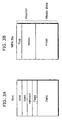
- the Box structure in the MP4 file is shown as FIG. 3B.
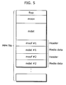
- the MP4 file is composed of 'fytp', 'moov' and, 'mdat' or 'moof', and 'fytp' is placed in the top of the MP4 file.
- Information for identifying an MP4 file is included in 'fytp', and media data is stored in 'mdat'.
- Each media data included in 'mdat' is called 'trak', and each 'trak' is identified by a 'trak' ID.
- header information on a sample included in each 'trak' of 'mdat' is stored in 'moov'.
- Boxes are hierarchically placed, and pieces of header information of audio media tracks and video media tracks are separately stored in a 'trak'.
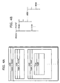
- a 'trak' Boxes are hierarchically placed, and the following information is stored in each Box in 'stbl': ( i ) sizes, decoding time and display starting time of samples; or ( ii ) information on randomly-accessible samples (FIG. 4B).
- Such randomly-accessible samples are called Sync samples, and a list of sample numbers of the Sync samples is shown by 'stss' in 'stbl'.
- the header information of all the samples in a 'trak' is stored in 'moov' in the above description, but it is possible to divide these 'trak's into fragments and store the header information on a fragment-by-fragment basis.
- the header information on each unit obtained by dividing the 'trak' is shown in 'moof'.
- the header information of samples to be stored in 'mdat' #1 can be stored in 'moof' #1.
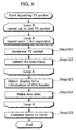
- step 101 the PES packet data is separated, from the payload of the inputted TS packet, by detecting the starting position of the PES packet.
- step 102 the starting position of an AU is detected from the payload of the separated PES packet.
- Step 101 and step 102 are repeated until the starting position of an AU is detected (Loop A), and the AU data for 1 AU is separated at the time of the detection.
- the display time information shown in the PES header is obtained in the step 103, and 'moov' and 'mdat' are made in the step 104.
- FIG. 7 is a flow chart showing the processing of step 104 in detail.
- the header information necessary for making Boxes in 'moov' is obtained by analyzing AU data.
- storage format of NAL units composing an AU is converted from a byte stream format to a NAL size format.
- step 203 Box data in 'moov' is made based on the header information of AUs obtained in the step 201.
- step 204 'mdat' data is made. Note that a Box for storing the header information, which includes the size and decoding time of a sample, for each sample is completed at the time when processing of all the AUs in a 'trak' is completed.
- a packet loss occurs at the time of receiving TS packets to be broadcast. Especially, in a case where they are received by a mobile terminal such as a mobile phone, packet losses frequently occur.
- TS packets it is possible to detect that AU data is lost because of a packet loss by checking whether continuity_counter value is discontinuous or not, but in the case of MP4, it is impossible to show that sample data is lost. This is the cause of the first problem that sample data cannot be correctly decoded because data is lost at the time of reproducing the MP4 file, resulting in video data with low picture quality being displayed.
- the storage format of the NAL unit must be converted from a byte stream format to a NAL size format.
- the boundary of the NAL units is detected by detecting a start code added to the top of the NAL unit.
- the boundary part is lost because of a packet loss, the boundary cannot be detected. This makes it impossible to separate the data of the NAL unit correctly.
- An object of this invention is to provide a multiplex scheme conversion apparatus that can avoid displaying the video data that cannot be correctly decoded to a user.
- the multiplex scheme conversion apparatus in the present invention ( i ) packet-multiplexes the coded media data using the second scheme which is different from the first scheme by which the coded media data has been packet-multiplexed and ( ii ) outputs the coded media data that is packet-multiplexed using the second scheme, and includes: a packet loss judgment unit that judges whether or not a packet loss has occurred in the coded media data that is packet-multiplexed using the first scheme; a loss information making unit that makes loss information concerning a loss of data, based on a position at which the data is lost in the coded media data, in the case where the packet loss judgment unit judges that a packet loss has occurred; and a multiplex unit that stores the loss information made by the loss information making unit in a packet that is multiplexed using the second scheme and to packet-multiplex the coded media data using the second scheme.
- this makes it possible to obtain information on the samples whose data is partly lost because of a packet loss of a TS packet that is multiplexed using the first scheme that is the MPEG-2 system TS without decoding the sample data, and therefore, it becomes possible to determine the operation of decoding or displaying samples in the system layer higher than, for example, the audio or video decode unit.
- the multiplex scheme conversion apparatus may further include a packet separation unit that separates a header from a payload of a packet of the coded media data that is packet-multiplexed using the first scheme.
- the multiplex scheme conversion apparatus may further include a frame separation unit that detects, in the payload separated by the packet separation unit, a boundary of frames in the coded media data and separate the frames, and in the multiplex scheme conversion apparatus, the loss information making unit makes loss information concerning a loss of data on a frame-by-frame basis based on a position at which the data is lost in the coded media data in the case where the packet loss judgment unit judges that a packet loss has occurred, and the multiplex unit stores loss information made, on a frame-by-frame basis, by the loss information making unit, in the packet that is multiplexed using the second scheme.
- the loss information making unit may make the information, as the loss information, indicating the area including frames ( i ) at which data necessary for decoding are not lost and ( ii ) that are placed continuously in a decoding order.
- this makes it possible to specify the area where samples can be correctly decoded. This can prevent samples whose data is lost from being decoded resulting in allowing a turbulent picture to be outputted, and thus it is possible to prevent the deterioration of reproduction quality.
- the multiplex scheme conversion apparatus may further include a table making unit that makes a table for registering a randomly-accessible frame, and in the multiplex scheme conversion apparatus, the multiplex unit judges whether or not data necessary for decoding a frame is lost in the frame, based on a position at which data is lost in the coded media data, at the time of registering, in the table, a randomly-accessible frame in the coded media data, and, in the case where data necessary for decoding a frame is lost in the frame, the multiplex unit does not register, in the table, the frame as a randomly-accessible frame.
- the multiplex scheme conversion apparatus may further include a conversion unit that converts a storage format of the coded media data.
- storage format has a narrower scope than “multiplex scheme” does. For example, it is a storage format of frame data.
- the frame is composed of a sub-frame unit
- the conversion unit ( i ) determines sub-frame data to be stored in the packet that is multiplexed using the second scheme and a size of the sub-frame data, based on the position at which data is lost in the coded media data, and ( ii ) converts the storage format by adding size information of the sub-frame unit to the top of each sub-frame unit.
- the frame may be composed of a sub-frame unit, and the conversion unit may insert such sub-frames indicating the presence of a packet loss into the position at which a packet loss has occurred in the coded media data and then packet-multiplex the coded media data using the second multiplex scheme.
- detecting a NAL unit for notifying packet loss information that is inserted in the sample data enables the decode unit to identify the position at which AU data is lost, and thus it becomes possible to perform appropriate error concealment processing.
- the loss information making unit may make information indicating whether or not data necessary for decoding a predetermined unit is lost, as the loss information.
- the demultiplexer in the present invention decodes packet-multiplexed data of coded media data and includes: a loss information extraction unit that extracts, from the multiplexed data, loss information concerning a loss of data; a loss information analysis unit that determines data to be decoded in the coded media data, based on the loss information extracted by the loss information extraction unit; and a decode unit that decodes the data to be decoded, determined by the loss information analysis unit.
- the demultiplexer may further include a loss information notification unit that makes a notification concerning reproduction quality to a user based on the loss information extracted by the loss information extraction unit.
- the present invention can be realized not only as ( i ) a multiplex scheme conversion apparatus and a demultiplexer like this, but also as ( ii ) a multiplex scheme conversion method and demultiplex scheme including steps that respectively correspond to the characteristic units of such a multiplex scheme conversion apparatus and a demultiplexer and as ( iii ) a program causing a computer to execute these steps.
- a program can be distributed via recording media such as CD-ROMs or communication media such as the Internet.
- the multiplex scheme conversion apparatus in the present invention can indicate the video data that cannot be correctly decoded, and thus it becomes possible to prevent the deterioration of reproduction quality.
- TS packets where coded video data of the MPEG-4 AVC are multiplexed are inputted, after that, AU data are separated from the TS packets, multiplexed into an MP4 and outputted.
- the coded data multiplexed into packets is not limited to the MPEG-4 AVC, video coded data such as the MPEG-4 visual and H. 263, the VC-1 that is on the stage of standardization by the Society of motion picture and television engineers (SMPTE), or audio coded data such as the MPEG-4 AAC and AMR may be used.
- TS packets that transmit video coded data but also audio or program information may be included in the TS packets to be inputted.
- TS packets including program information are obtained first, and then PIDs of TS packets that transmit video and audio coded data are determined. After that, TS packets are divided into video TS packets and audio TS packets based on PID values and then processed respectively.
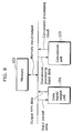
- FIG. 8 is a diagram showing the whole structure of a multiplex scheme conversion apparatus.
- the apparatus is composed of a data I/O unit 101 and a conversion unit 103.
- the data I/O unit 101 inputs TS packet data to store the data in a memory 102 and outputs the MP4 file for which multiplex scheme is converted, and the conversion unit 103 that obtains the TS packet data from the memory 102, separates and analyzes the AU data and the header of a PES packet, stores the analysis result in the memory 102, converts the separated AU data into an MP4 using the analysis result, and outputs the conversion processing result to the memory 102.
- the memory 102 includes a storage region of input and output data and a work region for temporally stores the conversion processing result or the AU data, and the sizes of the respective regions are changeable.
- the restructure unit 103 is a CPU here, but it can be exclusive hardware. Operations of the conversion unit 103 will be described in detail below.
- FIG. 9 is a block diagram showing the structure of the conversion unit 103.
- the conversion unit 103 includes a TS payload separation unit 201, a packet loss judgment unit 202, a PES separation analysis unit 203, an AU separation unit 204, a PES header analysis unit 205, a Box making unit 206 and a connection unit 207.
- the TS payload separation unit 201 separates the header of a TS packet and the payload and output them to the packet loss judgment unit 202.
- the packet loss judgment unit 202 judges a loss of a TS packet, performs error processing in the case where a packet loss is detected and outputs, to the PES separation analysis unit, the payload data on which error processing has already been performed.
- the procedure of the judgment on whether or not a packet loss has occurred is as follows: ( i ) obtaining continuity_counter value from the TS header; comparing the value with continuity_counter value of the TS packet inputted immediately before; and ( iii ) judging that a packet loss has occurred in the case where these values are discontinuous.
- the maximum value of continuity_counter is 15, and in the case where the continuity_counter value of a TS packet inputted immediately before is 15 and the continuity_counter value of current TS packet is 0, it is judged that continuity_counter values are cycled and there is no packet loss.
- a NAL unit whose NAL unit type is 25 and whose payload is vacant is inserted, as information for notifying the presence of a packet loss, in the top of the payload data of current TS packet employing a byte stream format.
- the NAL unit type of the NAL unit to be inserted can have an arbitrary value between 24 and 31 inclusive on condition that the NAL unit type is not used for other purposes.
- the NAL unit type of 0 and between 24 and 31 inclusive are defined as areas that can be arbitrary used by an application in the AVC standard.
- the PES separation analysis unit detects the starting position of the PES packet by searching the start code of the PES packet in the MPEG-4 AVC from the payload data of the TS packet into which the NAL unit for notifying the presence of a packet loss is inserted, the start code being between 0x000001EO to 0x000001EF inclusive.
- the payload may be separated using the size.
- the PES packet is divided into the header and the payload, and the header data is outputted to the PES header analysis unit 205 and the payload data is outputted to the AU separation unit 204.
- the stuffing data in the PES packet is not included in the payload data.
- the AU separation unit 204 the boundary of AUs is detected from the payload data of the PES packet and the AU data is separated, and the separated AU data is outputted to the Box making unit 206.
- a NAL unit for notifying the presence of a packet loss is also included in the AU data to be outputted to the Box making unit 206.
- the PES header analysis unit 205 judges whether the display time of the leading AU that starts in the PES payload is included in the data of the inputted PES header, and when included, the display time of AU is outputted to the Box generation unit 206.
- the Box making unit 206 makes 'moov' and 'mdat' including packet loss information based on the inputted AU data and the display time in the PES header, and outputs them to the connection unit 207.
- Box making unit 206 may make 'moof' or 'mfra' in addition to 'moov' and 'mdat'.
- connection unit 207 connects 'moov' with 'mdat' and outputs it as the data of the MP4 file.
- FIG. 10 is a flow chart showing the operation of the conversion unit 103.
- a loss of TS packet occurred is made in the step 301, and in the case where the occurrence of the packet loss is detected, a NAL unit for notifying the presence of a packet loss is inserted in the position at which a packet loss has been detected. Consequently, the header and the payload of the PES packet are separated from each other in the step 302, and the boundary of AUs is detected from the payload of the separated PES packet and the AU data is separated in the step 303. As shown in the Loop A of FIG. 10, the operation from step 301 to step 303 are repeated until the data for 1 AU can be separated.
- step 304 After the data for 1 AU is separated, in the step 304, the header of the PES packet is analyzed, judgment on whether the display time of the leading AU that starts in the PES payload is included is made, and when included, the display time of the AU is obtained. Note that the processing of step 304 may be performed in the processing of Loop A.
- step 305 the Box data in the MP4 file is made based on the AU data separated in the Loop A and the display time information obtained in the step 304.
- Loop B The processing of Loop B is repeated until the processing of all the AU data included in the TS packet to be inputted is completed, 'moov' and 'mdat' are completed at the time when the processing of all the AU data is completed, and in the step 306, 'moov' and 'mdat' are connected with each other, and the MP4 file is outputted.
- the Loop B includes processing of Loop A, step 304 and step 305. Note that 'fytp' is made, added to 'moov', and then outputted in the step 305 or added to 'moov' in the step 306. Note that an MP4 file where fragments are used may be outputted.
- step 305 at the time when 'moof' and 'mdat' for one fragment are determined, 'moof' and 'mdat' are outputted to finish Loop B, the outputted 'moof' and 'mdat' are sequentially connected with each other in the step 306.
- FIG. 11 is a block diagram showing the structure of the Box making unit 205.
- the Box making unit 205 includes an AU analysis unit 301, an error information making unit 302, an AU format conversion unit 303, and a Box data determination unit 304.
- the AU analysis unit 301 analyzes the AU data, obtains the information necessary for making a Box composing a conventional MP4 file, and outputs the analysis result to the Box data determination unit 304, such information being the display time of an AU, whether or not it is the AU IDR and the like.
- the analysis result outputted by the AU analysis unit 301 does not include the size of the AU.
- a Box indicating error information (loss information) or identification information for indicating the error information in 'mdat' is not included.
- the operation that is performed in the case where AU time information, an SPS or an PPS data that are referred to in decoding AU data is lost because of a packet loss will be described below.
- the data of AU is analyzed and then the time information is obtained.
- the parameter indicating the display order of pictures called Picture order count or SEI such as the Picture timing SEI and the Buffering period SEI are analyzed.
- the decoding time or display time of each AU is calculated according to a predetermined method.
- the decoding time or display time may be determined based on the frame rate.
- the descriptor is supplementary information of the coded media data that is described in the MPEG-2 system standard.
- a sample in the 'trak' of the MPEG- 4 AVC and ( ii - i ) each sample entry that stores an SPS and a PPS that are referred to by the sample or ( ii - ii ) each sample of the 'trak' in a parameter set are associated with each other one by one. Therefore, in the case where the data of an SPS or a PPS that is referred to in decoding a sample is lost, the same SPS or the PPS used in decoding the immediately-before-sample is referred to instead. Note that the default SPS or PPS that is previously set may be used.
- a NAL unit for notifying the presence of a packet loss is searched among AU data, and in the case where such NAL unit is detected, a Box data indicating error information is made. Further, the NAL unit data to be stored in 'mdat' is determined based on the presence or absence of the packet loss in the data of the NAL unit composing AUs, and it is determined that the size of AU data composed of NAL unit data is stored in 'mdat' as sample data. After that, those pieces of information are outputted to the Box data determination unit 304 together with the Box data indicating error information.
- the data of the NAL unit in the AU to be stored as sample data is converted from the byte stream format to the NAL size format, and the resulting AU data is outputted to the Box determination unit 304.
- the converted AU data outputted in the Box determination unit 304 becomes sample data in the MP4.
- FIG. 12 is a flow chart showing the operation of the Box making unit 205.
- the information necessary for making Boxes composing a conventional MP4 file is obtained from the inputted AU data.
- Box data indicating error information is made by detecting a NAL unit for notifying the presence of a packet loss from AU data.
- the NAL unit data to be stored as sample data in the MP4 file is determined.
- the NAL unit data which is determined as sample data is stored in the step 403 is converted to a NAL size format, and the converted NAL unit data composes a sample data is made. Consequently, in the step 405, the 'moov' data including the Box indicating error information is made.
- FIG. 13 is a flow chart showing the operation of step 405.
- Boxes composing a conventional MP4 file is made in the step 501 first, and next, a Box for storing error information is made in the step 502.
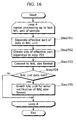
- FIG. 14 is a flow chart showing the operation of step 402.
- a technical word of sample is used for describing the Box data making method in the MP4 file, and one sample means 1 AU.
- search for judging whether a NAL unit for packet loss notification is included in AU data is performed.
- the starting position of a NAL unit is detected by checking starting from the leading data of an AU in order a start code prefix (0x000001, 3 bytes) of a byte stream format in a byte align position.
- the NAL unit type of the detected NAL unit is obtained, and in the case where the resulting value of the NAL unit type is a predetermined value, the NAL unit is judged as a NAL unit for notifying the presence of a packet loss.
- the NAL unit types of AUs are checked up to the last one in order, judgment on whether or not a NAL unit for notifying the presence of a packet loss is detected in a sample is made in the step 602.
- the processing of step 603 is performed in the case where a NAL unit for notifying the presence of a packet loss is detected, in contrast, in the case where a NAL unit for notifying the presence of a packet loss is not detected, the Box data making processing is completed.
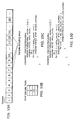
- FIG. 15A is the diagram of sample data in the coded data of AVC, in the diagram, the sample data are placed in a decoding order and, the numbers in the figure show sample numbers respectively.
- a NAL unit for notifying the presence of a packet loss is detected in the NAL unit data in the samples whose sample numbers are 7, 9 and 15.
- samples whose sample numbers are 1 to 15 the procedure taken at the time of making a Box indicating error information will be described below. Note that the name of the Box indicating error information is Error sample box.
- a NAL unit for notifying the presence of a packet loss is detected in the step 601 as to first to sixth samples, it is judged in the step 602 that a NAL unit for notifying the presence of a packet loss is present in a sample, and the processing is completed without updating the table data of Error sample box.
- a NAL unit for notifying a packet loss is detected in the seventh sample in the step 601, it is judged in the step 602 that the table data of Error sample box is updated, and the update processing is performed in the step 603.
- a sample number 7 is stored by adding the entry of a table in order to indicate that a packet loss is included in the seventh sample.
- FIG. 15C is a syntax example of Error sample box, and error_sample_number shows the sample number of a sample whose NAL unit data is partly lost because of a packet loss.
- the Error sample box is placed immediately below 'stbl' in trak in 'moov', and it is placed immediately below a track fragment run box ('traf') in 'moof', but it may be placed immediately below one of the other Boxes.
- an Error samle Bbx is made only in the case where a sample whose data is lost is present in a media track, but an Error sample box whose entry is vacant may be made even in the case where a sample whose data is lost is not present.
- these samples are given an error_sample_number obtained by counting these samples starting from the leading sample whose sample number is 1, the leading sample being included in 'traf'. For example, in the case indicating that ten samples are included in 'traf' and that the data of third and fifth samples are lost because of packet losses, two entries are made, one of which being assigned 3 and the other one of which being assigned 5 as its error_sample_number.
- tr_flags in a track fragment run box ('trun'), the tr_flags being a field indicating flag information concerning the header information of each sample.
- error_nal_unit_number is a number for identifying a NAL unit whose data is lost, and in the case where the second and the fourth NAL units in a sample are lost, two entries whose error_nal_unit_numbers are 2 and 4 respectively are assigned. In the entries, a NAL unit type may be shown. Further, an error_nal_unit_number is used for identifying a video packet in the MPEG-4 visual or a slice in H. 263.
- the information on not only a packet loss but also a bit error may be obtained, it is possible to store the information for identifying a sample or a NAL unit whose sample data includes a bit error.
- step 701 valid data in each NAL unit in an AU is determined and separated.
- valid data in the NAL unit whose starting position has already been detected immediately before is determined as the data up to immediately before the NAL unit for notifying the presence of a packet loss.
- the data of NAL units that follow the detected NAL unit for notifying the presence of a packet loss becomes invalid, in other words, the presence of NAL units placed before the next NAL unit whose starting position is to be detected becomes invalid.
- the NAL unit to which the data including an invalid part cannot be specified, or because, even if specified, the size of the lost data is unknown and the data cannot be used in decoding.
- all the NAL unit data is regarded as valid data. Note that zero_byte and a start code prefix are not included in the NAL unit data separated as valid data.
- the size of the valid data separated in the step 701 is obtained in the step 702.
- the NAL unit data including the valid data is converted to the NAL size format based on the size obtained in the step 702.
- the size of the field indicating the size of the NAL unit is variable within the range of 1 to 4 in the NAL size format, but the field size is regarded as given previously.
- a NAL unit for error notification is inserted as a NAL size format.
- the processing from the above step 701 to step 705 (Loop A) is repeated until the processing of the last NAL unit in a sample is completed. Note that the size of a sample is determined at the time when the size of the last NAL unit in the sample is determined.
- NAL unit data included in the payload of a TS packet may be stored without throwing away the data that has been judged as invalid.
- a specific NAL unit (called a NAL unit for complementing a packet loss from here) for stuffing the lost part may be inserted.
- the error information may be shown only in the NAL unit for error notification, and an Error sample box may not be made.
- the valid data in the NAL unit is determined based on the information separately shown in the step 701.
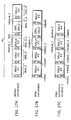
- FIG. 17 and FIG. 19 respectively show a concrete example of determining valid NAL unit data and converting it to the NAL size format.
- SCP, Nal_len, ERR_NALU is a start code prefix in a byte stream format, the size of a field showing the size of a NAL unit in the NAL size format, and a NAL unit for error notification respectively.
- FIG. 17 is an example where NAL unit data because of a packet loss occurs without crossing a NALU boundary.
- FIG. 17A shows before-conversion AU data. The AU is composed of four NAL units of NALU #1 to NALU #4, and a packet loss occurs in the third NAL unit.
- the NALU #3 is basically composed of data in the regions shown in the figure as “receive 1", “lost” and “receive 2", but ERR_NALU is inserted immediately after the data of the "receive 1" because a "lost” region is lost because of a packet loss.
- ERR_NALU is inserted immediately after the data of the "receive 1" because a "lost” region is lost because of a packet loss.
- the data of "receive 1" part is stored as the sample data of'mdat'.
- the NAL_len field value is size3_1 at the time when converting the data of NALU #3 to the NAL size format.
- FIG. 17B shows the structure of AU data outputted after conversion. Note that the data structure of AU at the time of storing all the NAL unit data included in the payload of a TS packet without inserting a NAL unit for error notification is shown as FIG. 17C, and the size of NALU #3 is the total of size3_1 and size3_2 (the size of "receive 2").
- FIG. 18 is an example where NAL unit data is lost because of a packet loss crossing the boundary of NAL units.
- FIG. 18A shows before-conversion AU data.
- the AU is composed of four NAL units of NALU #1 to NALU #4, and the data is lost crossing a NAL unit, more specifically, from the ending part of NALU #2 to the leading part of NALU #3 (the data of the region shown as "lost” in the figure).
- the data of "receive 1" part in the figure becomes valid in NALU #2.
- NALU #3 the data immediately after ERROR_NALU to the data up to the starting position of NALU #4 becomes invalid because the starting position of a NAL unit cannot be detected.
- the data of NALU #3 is not stored in the sample data.
- the data of "receive 2" part in the figure becomes invalid.
- FIG. 18B shows the structure of AU data outputted after conversion.
- FIG. 19 is an example where NAL unit data is lost because of a packet loss crossing the boundary of AUs.
- FIG. 19A shows before-conversion AU data.
- Three AU data from AU #1 to AU #3 are composed of NALU #1 to NALU #4, NALU #5 to NALU #8 and NALU #9 to NALU #12 respectively.
- data from the middle of NALU #4 to the leading part of NALU #9 is lost crossing AU #2 (the data of a region shown as "lost" in the figure).
- the valid data in AU #1 to AU #3 is described below.
- AU #1 all the data from NALU #1 to NALU #3 and the data of nal4_size obtained in NALU #4 become valid. As all the AU #2 data is lost, there is no valid data.
- a sample for storing AU #3 will be stored next to the sample for storing AU #1.
- the total of reproduction duration of AU #1 and AU #2 is stored.
- the data from NALU #10 to NALU #12 become valid.
- ERR_NALU may be inserted into the leading part of NALU #10 in the case where it is possible to determine that NALU #10 is not the leading NAL unit in AU #3.
- FIG. 19B shows the structure of AU data outputted after conversion.
- FIG. 19C shows the structural example of AU data outputted at the time of using a NAL unit for complementing a packet loss.
- the data of AU #1 and AU #3 are the same as the data shown as FIG. 19B, but in this example, the data of AU #2 is also outputted.
- the output data of AU #2 includes only the NAL unit for complementing a packet loss, and the size of the NAL unit for complementing a packet loss can be estimated based on the information on whether it is the coded bit rate of the MPEG-4 AVC data and a fixed frame rate. In this way, inserting a NAL unit for complementing a packet loss makes it possible to store the sample data in the MP4 by holding the original fixed bit rate as much as possible also in the case where the data is lost because of a packet loss while video data is being coded in a fixed bit rate.
- the slice data of an AU is lost, the same data as the data of the AU that is placed immediately before in a decoding or displaying order is stored. In other words, it is possible to reconstruct and record the AU data by performing error concealment processing on a slice-by-slice basis. Further, it is also possible to present the information indicating that the AU data is reconstructed.
- SEI Supplemental enhancement information
- error information may be stored in the payload or the Error sample box of the NAL unit for error notification, such error information being the rate of data that is lost because of a packet loss, the rate of slices whose data are lost in an AU or the frequency of bit errors.
- error information being the rate of data that is lost because of a packet loss, the rate of slices whose data are lost in an AU or the frequency of bit errors.
- a Box for indicating the type of error information to be described may be stored in 'moov' or 'moof'.
- the method of making a Box for error notification or inserting a NAL unit for error notification in sample data is applicable also in the case of converting, to an MP4 file, the coded media data multiplexed by a Real-time transmission protocol (RTP) packet.
- RTP Real-time transmission protocol
- judgment on whether a packet loss occurred or not can be made by checking the continuity of sequence numbers added to the headers of the RTP packets.
- error information such as an Error sample box is added to each 'trak', but the unit for adding error information is not limited to this.
- error information can be added on an MP4 file-by-MP4 file basis.
- error information can be placed immediately below 'moov'.
- at the time of using a fragment it may be placed in the 'moof' of the last fragment or in the Box of 'mfra' and so on. This enables notifying a user of information such as a loss rate (lost data/all data) of sample data and the rate of duration to the whole reproduction duration during which audio and video can be reproduced concurrently.
- the multiplex scheme conversion apparatus concerning the second embodiment of the present invention will be described with reference to FIG. 20 and FIG. 21.
- the structure of the multiplex scheme conversion apparatus is approximately the same as the multiplex scheme conversion apparatus in the first embodiment, but it differs in its operation performed by the Box data determination unit 304 when making 'stss' that is the table of a Sync sample. Therefore, only the 'stss' making method will be described below.
- an IDR AU is a Sync sample regardless of whether data in a sample is lost or not.
- the Sync sample becomes the sample from which decoding is started at the time of random access processing, the Sync sample that cannot be correctly decoded may cause a problem that samples following the Sync sample in a sequence cannot be decoded correctly. Therefore, only an IDR AU whose data is not lost is made to be a Sync sample in the multiplex scheme conversion apparatus of this embodiment. This makes it possible to obtain at least a non-turbulent Sync sample at the time of starting decoding from the Sync sample.
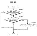
- FIG. 20 is a flow chart showing the operation at the time of making 'stss' in the Box data determination unit 304.
- step 801 judgment on whether the NAL unit of an IDR slice is included in a sample data or not is made. Here, whether it is the NAL unit of the IDR slice or not is identified by its NAL unit type. Current processing is completed in the case where a NAL unit of the IDR slice is not included, but in the case where such a NAL unit is included, the processing of step 802 is performed. Also, in the step 802, judgment on whether a NAL unit whose data is lost because of a packet loss is included in a sample data is made based on the error information for each sample obtained in the error information making unit 302.
- Sync samples samples whose data are not lost in the slice, the SPS or the NAL unit of a PPS in an AU including an IDR slice.
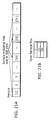
- FIG. 21 shows a concrete example at the time of making 'stss' by the operation shown in the flow chart as FIG. 20.
- FIG. 21A shows samples aligned in the ascending order of sample numbers.
- the samples whose sample numbers are 1, 11, 21 and 31 include a NAL unit of an IDR slice, but the data in the sample data of the twenty-first sample is lost.
- the first, eleventh, twenty-first and thirty-first samples are considered as candidate Sync samples in the step 801, but in the step 802, it is determined that the twenty-first sample is not made to be a Sync sample.
- the first, eleventh and thirty-first samples are added to the table of 'stss' (FIG. 21B).
- samples to be recorded in 'mfra' as randomly-accessible samples can be determined in a similar way.
- making 'stss' using the above-mentioned method and making Error sample box can be selected independently. For example, it is possible to make 'stss' using the above-mentioned method but not to make Error sample box.
- the multiplex scheme conversion apparatus concerning the third embodiment of the present invention will be described with reference to FIG. 22 to FIG. 24.
- the structure of the multiplex scheme conversion apparatus is approximately the same as the structure of the multiplex scheme conversion apparatus in the first embodiment, but it differs in its operation of step 402 in FIG. 12 performed by the error information making unit 302 when making a Box indicating error information of a sample. Therefore, only this operation will be described below.
- a Box indicating whether up to which sample, among samples that follows the Sync sample, can be correctly decoded is made at the time when decoding is started from the Sync sample in the multiplex scheme conversion apparatus. At the time of reproducing an MP4 file made in the multiplex scheme conversion apparatus referring to this Box makes it possible to determine the sample to be displayed after the samples guaranteed as correctly decodable are specified.
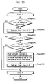
- FIG. 22 is a flow chart showing the operation performed at the time of making a Box indicating error information.
- err_free_flag is a flag indicating that data loss has not occurred in samples placed between the sample from which a sequence is started to the current sample, and its initial value is 0.
- step 901 judgment on whether or not the NAL unit of an IDR slice is included in a sample is made, and if included, err_free_flag is set to 1 in the step 902.
- step 903 whether err_free_flag is 1 or not is judged as follows: the processing of step 904 is performed in the case where the value is 1; or in the case where the value is 0, the following steps are skipped and the processing of the next sample is started.
- step 904 judgment on whether or not the data of the NAL unit that composes a sample is lost is made. Furthermore, it is possible to judge that data is not lost in the step 904 in the case where NAL unit data of an SPS or a PPS is not lost. In the case where a NAL unit whose data is lost is included, the sample number of the immediately-before sample is added to the table showing the list of last samples of the respectively corresponding error free areas in the step 905.
- error-free area means the area of samples that are placed in a decoding order and guaranteed as free from a data loss.
- step 905 is skipped. In this way, the processing from step 901 to step 905 is repeated until the processing of the last sample in a 'trak' is completed.
- guaranteeing that a data loss has not occurred indicates that an error is not detected judging from the continuity_counter value of a TS packet, but does not always guarantee that no data loss has occurred. Note that, in the case where packet losses can be detected more correctly based on packet loss information except continuity_counter, an error may be detected using the information.
- FIG. 23 shows a concrete example at the time of making a Box for storing error information using the operation shown in the flow chart as FIG. 22.
- FIG. 23A shows two continuous sequences, each of which being composed of ten pieces of samples. In the sequence #1, starting from the first sample, the data of the seventh and ninth samples are lost, and in the sequence #2, starting from the eleventh sample, the data of the sixteenth sample is lost. The procedure taken at the time of determining an error-free area will be described below. First, the err_free_flag is set at 1 for the first sample. As it is judged that the data of samples up to the sixth sample are not lost in the step 904, processing of steps 905 and 906 are skipped and the value of err_free_flag is held at 1.
- FIG. 23B shows a Sync sample table.
- FIG. 23B shows the table of the last sample of an error-free area.
- FIG. 23C show that samples whose sample numbers are one to six are included in the error-free area in the sequence #1, and that samples whose sample numbers are eleven to fifteen are included in the error-free area in the sequence #2.
- FIG. 23D is an example syntax of Error free end sample box that is a Box indicating a list of last samples of the respectively corresponding error-free areas, and end_sample_number shows the sample numbers of the last samples of the respectively corresponding error-free areas.
- An Error free end sample box is placed immediately below 'stbl' in the 'trak' in 'moov', or immediately below a track fragment run box ('traf') in 'moof', but it may be placed immediately below another Box.
- the Gradual decoder refresh point indicates the sample having the following features: It cannot be decoded correctly; It enables decoding the following samples correctly under the condition that the specified number of following samples are decoded in a decoding order; and It enables indicating the sample from which decoding is started in the case where there is a need for starting decoding from the sample placed earlier by the specified number in the decoding order in the interest of decoding a sample correctly.
- FIG. 24A shows six continuous sequences, each of which being composed of ten samples. Here, all the sample data are completely available in the four sequences of #1, #3, #4 and #6, but in contrast, a sample whose data is lost is included in the sequences of #2 and #5.
- FIG. 24C is a list of leading samples in the corresponding sequences where sample data in a sequence are completely available.
- FIG. 24B is a list of Sync samples in the case where leading samples of the respectively corresponding sequences are made to be Sync samples.
- FIG. 24D is an example syntax of the Error free sequence box indicating the list of the leading sample of the sequence where a data loss does not occur.
- sequence_start_sample_number in the syntax shows the sample number of the leading sample of the sequence.
- an index such as good, medium and bad as a parameter indicating the quality of the reproduction video obtained at the time of reproducing a sequence depending on the data loss rate in a sequence in addition to the leading sample numbers of a sequence. For example, it is possible to determine the quality depending on the data loss rate, the appearance frequency of intra-coded AUs and the rate of intra-macroblocks. Further, it is possible to store the information indicating the samples that can be decoded correctly in the sequence.
- SPSs or PPSs in each sample makes it possible to know whether or not the data of the reference-destination sample is lost at the time of decoding the sample.
- Error free sequence box is placed immediately below 'stbl' in the 'trak' in 'moov', and immediately below a track fragment run box ('traf') in 'moof', but it may be placed immediately below another Box.
- Error sample boxes In combination, Error sample boxes, Error free end sample boxes and Error free sequence boxes that have already been described in the first to third embodiments.
- using an Error sample box in combination with an Error free end sample box makes it possible to identify the sample whose data is lost, among samples outside the error-free area, and determine samples to be decoded.
- the part to be converted from a byte stream format to a NAL size format and the part to which the information indicating a data loss is added.
- data loss information to the NAL unit data transmitted in a form of a NAL size format or a format used in video distribution on the Internet such as Real time transmission protocol (RTP).
- RTP Real time transmission protocol
- AU format conversion unit 303 can be used. Note that it is possible to convert the format of the coded data into a byte stream format in order to simplify the coding processing of the MPEG-4 AVC, and for example, it is possible to apply the processing of the AU format conversion unit 303 at the time of multiplexing the coded data outputted from the coding unit using a multiplex scheme such as a TS and an MP4 whose storage format of coded data is different.
- processing for complementing data loss can be omitted because an error is not present in a stream at the time of coding.
- the byte stream format is converted to the NAL size format in the AU format conversion unit 303, but it is possible to convert the NAL size format to the byte stream format at the time when the format of the output data at the time of coding is converted into the NAL size format.
- the demultiplexer concerning the fourth embodiment of the present invention will be described with reference to FIG. 25 to FIG. 27.
- the demultiplexer inputs the MP4 file made by the multiplex scheme conversion apparatus in the first to third embodiments, demultiplexes, decodes and displays the AU data.
- This demultiplexer determines decoding and displaying operations by referring to error information shown in an Error sample box and the like. Therefore, it can determine the operation of skipping to the next sequence and the like based on file-format-level information in the case where a lot of samples that cannot be decoded correctly are included in a sequence, and as a result, it can prevent the deterioration of reproduction quality caused by decoding and displaying samples that cannot be decoded correctly.
- a decode unit or a display unit that performs different error concealment processing can obtain the same output result also in the case where a decode unit or a display unit that performs different error concealment processing by determining decoding and displaying operations based on the file-format-level information.
- a Box indicating error information (loss information) is added.
- the operation performed at the time of reproducing a 'trak' of the MPEG-4 AVC will be described below.
- a 'trak' to be reproduced is not limited to the MPEG-4 AVC, it may be coded video data such as H. 263 or the MPEG-4 visual, coded audio data such as the MPEG-4 AAC or AMR or the coded data that concurrently reproduces a 'trak' composed of video and audio data.
- FIG. 25 is a block diagram showing the structure of the demultiplexer.
- the demultiplexer includes a header demultiplex unit 401, a header memory 402, a 'mdat' memory 403, a sample obtainment unit 404, an error information analysis unit 405, and a decoding and reproducing unit 406, and it starts reproduction processing triggered by reproduction starting time to be inputted from outside.
- the reproduction starting time becomes zero second at the time of starting reproduction processing from the top of a file, or it becomes ten seconds at the time of starting reproduction processing from the position ten seconds later from the top. Note that there is a case where a Sync sample having reproduction starting time that matches the inputted reproduction starting time is not present at the time of starting decoding and reproduction from a Sync sample.
- decoding and reproduction is started from one of the immediately-before Sync sample and the immediately-after Sync sample that has reproduction starting time nearest to the inputted reproduction starting time. Note that it is also possible to start reproduction from not a Sync sample but the sample shown as a Gradual decoder refresh point.
- the header separation unit 401 separates a header part including 'moov' and 'moof' and a data part composed of 'mdat' from the MP4 file, outputs the data of the header part to a header memory 402 and outputs the data of 'mdat' to a 'mdat' memory 403.
- the sample obtainment unit 404 determines a Sync sample from which decoding is started based on the reproduction starting time information inputted from outside. As to the following samples, the sample number of the Sync sample is outputted to an error information analysis unit 405 at the time of obtaining the header information of the Sync sample.
- the error information analysis unit 405 obtains and analyzes error information in the sequence that starts from the Sync sample number inputted by the sample obtainment unit 404 from an Error sample box, an Error free end sample box or an Error free sequence box, determines the sample to be decoded in a sequence, and after that, outputs the list of the samples to be decoded to the sample obtainment unit 404. Also, the error information analysis unit 405 outputs the obtained loss information to the loss information notification unit 406C of the decode and display unit 406. Also, in the case where data loss information for each NAL unit of a slice can be obtained, the information indicating a slice to be decoded in a sample may be outputted.
- samples to be decoded may be determined on the basis of predetermined number of samples instead of being determined on a Sync sample-by-Sync sample basis.
- the sample obtainment unit 404 analyzes 'moov' or 'moof', obtains the data and the display time of the samples to be decoded, the samples being determined by the error information analysis unit, and outputs them to the decode and display unit 406.
- 'moov' or 'moof' are obtained from the header memory 402 and the data of samples are obtained from the 'mdat' memory 403. Note that, in the case where decoding time is different from display time, both of them may be outputted to the decode and display unit 406.
- the decode and display unit 406 includes a decode unit 406a, a sample display unit 406b and a loss information notification unit 406c.
- the decode unit 406a decodes sample data.
- the sample display unit 406b displays the decoded sample data according to their display time.
- the loss information notification unit 406c notifies a user of the information such as the loss rate (lost data/all data) of sample data based on the loss information, and makes an inquiry as to whether the MP4 file should be reproduced or not.
- the sample obtainment unit 404 outputs the reproduction indication signal to the sample obtainment unit 404.
- the error information analysis unit 405 may not determine samples to be decoded but output the error information, to the decode and display unit 406, such as the information of samples whose data are lost or an error-free area including such samples.
- the decode and display unit 406 may determine samples or slice data to be decoded based on the inputted error information or the information shown by the NAL unit for error notification inserted into the sample data. At this time, a list of decoded samples is not outputted to the sample obtainment unit 404.
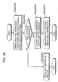
- FIG. 26 is a flow chart showing the operation performed at the time of reproducing the MP4 file.
- the loss information notification unit 406c notifies a user of the MP4 file or loss information for each 'trak' that are obtained from the header information ('moov') by the error information analysis unit 405 and inquires the user of whether the user should reproduce the MP4 file or not (step 1001). Next, whether or not the user indicated reproduction in reply to this inquiry is judged (step 1002). In the case where the indication is that reproduction should be performed (Yes in the step 1002) as a result of the inquiry, the loss information notification unit 406c orders reproduction by outputting a reproduction indication signal to the sample obtainment unit 404 (step 1004). It starts reproduction from the inputted reproduction starting time, decodes samples until the last sample is decoded or the user indicates the completion of the reproduction (step 1005). On the other hand, in the case where the indication is that reproduction should not be performed (No in the step 1002) as a result of the inquiry, the user is notified that the MP4 file should not be reproduced (step 1003).
- FIG. 27 is a flow chart showing the operation performed in the step 1005.
- a Sync sample from which decoding is started is determined based on the inputted reproduction starting time in the step 1101.
- the processing of Loop B is performed.
- the Loop B indicates repeating the processing of step 1102 to 1106, and it is repeated every time a new Sync sample is decoded in decoding.
- error information as to whether data is lost or not is obtained in the samples between ( i ) an Error sample box, an Error free end sample box or an Error free sequence box and ( ii ) the next Sync sample.
- samples to be decoded in the sequence are determined based on the error information obtained in the step 1102, and a list of sample numbers of samples to be decoded is stored in a table.
- samples to be decoded based on the table made in the step 1103 are decoded and displayed in order in the processing of Loop A.
- the Loop A is composed of the processing from step 1104 to step 1106, and it is repeated until the processing of the last sample to be decoded at the time of reproduction is completed.
- sample data and sample display time are obtained by analyzing 'moov' or 'moof'.
- sample data obtained in the step 1104 are decoded, and in the step 1106, sample data decoded in the step 1105 are displayed based on the display time obtained in the step 1104.
- a coding type of slice NAL units composing each sample periodically changes to another coding type
- the coded type of the slice NAL unit in each of samples in a period is IBBPBBPBBPBBPBB in a decoding order.
- I shows an intra slice or a sample composed of IDR slices
- B shows a sample composed of bi-directionally-predictive slices
- P shows a sample composed of one-directionally-predictive slices.
- the loss information notification unit 406c inquires the user of whether or not the MP4 file should be reproduced, but another or no inquiry may be made. For example, the loss information notification unit 406c may simply notify the user of the information such as loss rate of sample data instead of inquiring the user of whether the MP4 file is reproduced or not. Also, the loss information notification unit 406c may judge the information such as loss rate of sample data using a predetermined threshold and, in the case where the condition is satisfied, output reproduction indication signal to the sample obtainment unit 404. Further, the loss information notification unit 406c may judge the information such as loss rate of sample data using a predetermined threshold and, in the case where the condition is not satisfied, inquire the user of whether the MP4 file is reproduced or not.
- the multiplex scheme conversion apparatus can also reproduce a conventional MP4 file.
- the demultiplexer concerning the fifth embodiment of the present invention will be described with reference to FIG. 28.
- the demultiplexer inputs the MP4 file made by the multiplex scheme conversion apparatus in the first to third embodiments, multiplexes, decodes and displays the AU data.
- the demultiplexer determines decoding or displaying operations by referring to the error information shown in the NAL unit for error notification inserted into the sample data. Note that a Box indicating error information does not need to be added to the MP4 file to be inputted to the demultiplexer.
- the operation performed at the time of reproducing a 'trak' of the MPEG-4 AVC will be described below, but a 'trak' to be reproduced is not limited to the MPEG-4 AVC. It may be the video coded data such as H. 263 or the MPEG-4 visual, audio coded data such as the MPEG-4 AAC or AMR or coded data that reproduces 'trak's composed of video and audio data concurrently.
- FIG. 28 is a flow chart showing the operation of this demultiplexer.
- the Sync sample from which decoding is started is determined based on the reproduction starting time inputted in the step 1101.
- the processing of Loop A is performed after the processing of step 1101 is completed.
- the Loop A indicates repeating the processing of step 1102 to 1105, and it is repeated until the processing of the last sample to be decoded in reproduction is completed.
- the data of samples to be decoded is obtained.
- the following processing of step 1103 to step 1105 is performed by the decode and display unit 406.
- a NAL unit for error notification and a sample is identified in a sample data obtained in the step 1102 and in the case where it is shown that the sample is not correctly decoded, the sample is not decoded. Consequently, the data of the slice NAL unit to be decoded, such slice NAL data being determined in the step 1103, is decoded in the step 1104, and in the step 1105, the decoded sample data is displayed based on the display time.
- FIG. 29 is a block diagram showing the whole structure of the system for realizing a content distribution service through broadcasting and communication.
- a mobile phone ex105 or a disc recorder ex104 such as a DVD recorder receives a TS packet sequence where coded digital media data is multiplexed.
- the mobile phone ex105 converts the received TS packet sequence into an MP4 by using its internal multiplex scheme conversion apparatus in the present invention and then records it in an SD card ex106.
- the recorded MP4 file can be viewed or listened to by a mobile phone ex105 having a demultiplexer in the present invention, a disc recorder ex104 or a personal computer that is not shown.
- the MP4 file it is possible to view and listen to the MP4 file by attaching it to electric mail and, via the mobile phone ex105 to the wireless base station ex107, sending it to another mobile phone ex108 having a demultiplexer in this invention. Furthermore, it may be downloaded from the mobile phone ex105 to the mobile phone ex108 or distributed in pseudo-streaming by using a protocol such as the Hyper text transport protocol (HTTP) and the Transmission control protocol (TCP) instead of attaching it to electric mail.
- HTTP Hyper text transport protocol
- TCP Transmission control protocol
- the disc recorder ex104 can make its internal multiplex scheme conversion apparatus in the present invention to convert the received TS packet sequence to the MP4 and record it in an SD card, an optical disc such as a DVD and a hard disc. Also, it may distribute, in download or in pseudo-streaming, the recorded MP4 file to a mobile phone or a personal computer that is not shown in any figure. Note that it is also possible to record a TS packet sequence in an SD card and convert it to an MP4 file in distribution.
- the MP4 file like in the case where the above-mentioned broadcasting data is received, also in the case where the TS packet sequence distributed from the content server ex102 via the Internet are received by the mobile phone ex105, or the disc recorder ex104.
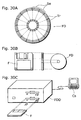
- FIG. 30A to 30C are an illustration of the case where the multiplex scheme conversion method in the multiplex scheme conversion apparatus and the demultiplex scheme in the demultiplexer in the respective embodiments are performed in a computer system using a program recorded in a recording medium such as a flexible disc.
- FIG. 30A shows an example of the physical format of a flexible disc as a recording medium body.
- FIG. 30B shows a flexible disc and the front view and the cross-sectional view of the appearance of the flexible disc.
- a flexible disc (FD) is contained in a case F, a plurality of traks (Tr) are formed concentrically on the surface of the disc from the periphery into the inner radius of the disc, and each trak is divided into 16 sectors (Se) in the angular direction. Therefore, in the case of the flexible disc storing the above-mentioned program, the program is recorded in an area allocated for it on the flexible disc (FD).
- FIG. 30C shows the structure for recording and reading out the program on the flexible disc (FD).
- the program for realizing the method for converting multiplex scheme in the multiplex scheme conversion apparatus and the demultiplex scheme performed in the demultiplex apparatus is recorded on the flexible disc (FD)
- the program is written on a flexible disc by the disc drive of the computer system (Cs).
- the multiplex scheme conversion method in the multiplex scheme conversion apparatus and the demultiplex method in the demultiplexer are configured in the computer system by the program on the flexible disc, the program is read out from the flexible disc through a flexible disc drive and transferred to the computer system.
- a flexible disc is described as a recording medium above, but the recording medium is not limited to a flexible disc, and an optical disc may be described as a recording medium in a similar way. More specifically, the recording medium is not limited to this, any recording medium such as IC cards and Rom cassettes are also available.
- the multiplex scheme conversion apparatus in the present invention is applicable for apparatuses that convert, to an MP4, the coded data such as the MPEG-4 AVC that is sent by the TS, and record or send it. Also, this multiplex scheme conversion apparatus is particularly effective for mobile phones that receive digital broadcasting.
Landscapes
- Engineering & Computer Science (AREA)
- Multimedia (AREA)
- Signal Processing (AREA)
- General Engineering & Computer Science (AREA)
- Mechanical Engineering (AREA)
- Chemical & Material Sciences (AREA)
- Combustion & Propulsion (AREA)
- Physics & Mathematics (AREA)
- Acoustics & Sound (AREA)
- Aviation & Aerospace Engineering (AREA)
- Compression Or Coding Systems Of Tv Signals (AREA)
- Time-Division Multiplex Systems (AREA)
Priority Applications (1)
| Application Number | Priority Date | Filing Date | Title |
|---|---|---|---|
| EP06110686A EP1670254A1 (de) | 2004-01-15 | 2005-01-14 | Vorrichtung zur Konvertierung von Multiplexschemas |
Applications Claiming Priority (2)
| Application Number | Priority Date | Filing Date | Title |
|---|---|---|---|
| JP2004007817 | 2004-01-15 | ||
| JP2004007817 | 2004-01-15 |
Related Child Applications (1)
| Application Number | Title | Priority Date | Filing Date |
|---|---|---|---|
| EP06110686A Division EP1670254A1 (de) | 2004-01-15 | 2005-01-14 | Vorrichtung zur Konvertierung von Multiplexschemas |
Publications (2)
| Publication Number | Publication Date |
|---|---|
| EP1555827A2 true EP1555827A2 (de) | 2005-07-20 |
| EP1555827A3 EP1555827A3 (de) | 2005-10-05 |
Family
ID=34616884
Family Applications (2)
| Application Number | Title | Priority Date | Filing Date |
|---|---|---|---|
| EP06110686A Ceased EP1670254A1 (de) | 2004-01-15 | 2005-01-14 | Vorrichtung zur Konvertierung von Multiplexschemas |
| EP05000655A Withdrawn EP1555827A3 (de) | 2004-01-15 | 2005-01-14 | Vorrichtung zur Konvertierung von Multiplexschemas |
Family Applications Before (1)
| Application Number | Title | Priority Date | Filing Date |
|---|---|---|---|
| EP06110686A Ceased EP1670254A1 (de) | 2004-01-15 | 2005-01-14 | Vorrichtung zur Konvertierung von Multiplexschemas |
Country Status (4)
| Country | Link |
|---|---|
| US (1) | US7567584B2 (de) |
| EP (2) | EP1670254A1 (de) |
| KR (1) | KR101073777B1 (de) |
| CN (1) | CN1642221A (de) |
Cited By (6)
| Publication number | Priority date | Publication date | Assignee | Title |
|---|---|---|---|---|
| EP3038369A1 (de) * | 2014-12-23 | 2016-06-29 | Imagination Technologies Limited | In-band-qualitätsdaten |
| CN107925781A (zh) * | 2015-08-03 | 2018-04-17 | 松下知识产权经营株式会社 | 发送方法、接收方法、发送装置以及接收装置 |
| US10433024B2 (en) * | 2011-03-16 | 2019-10-01 | Samsung Electronics Co., Ltd. | Method and apparatus for configuring content in a broadcast system |
| CN110662084A (zh) * | 2019-10-15 | 2020-01-07 | 北京齐尔布莱特科技有限公司 | 一种mp4文件流直播的方法、移动终端及存储介质 |
| CN111614976A (zh) * | 2014-09-12 | 2020-09-01 | 松下知识产权经营株式会社 | 发送装置、接收装置、发送方法以及接收方法 |
| WO2023100781A1 (en) * | 2021-12-03 | 2023-06-08 | Sharp Kabushiki Kaisha | Systems and methods for reducing latency in decoding of coded video data |
Families Citing this family (33)
| Publication number | Priority date | Publication date | Assignee | Title |
|---|---|---|---|---|
| US7483532B2 (en) * | 2003-07-03 | 2009-01-27 | Microsoft Corporation | RTP payload format |
| JP4372031B2 (ja) * | 2005-03-10 | 2009-11-25 | 株式会社東芝 | 信号処理装置及び信号処理方法 |
| JP4891898B2 (ja) * | 2005-03-22 | 2012-03-07 | パナソニック株式会社 | ストリームデータ記録装置、ストリームデータ記録再生装置、ストリームデータ再生装置、ストリームデータ編集装置、ストリーム記録方法、及びストリーム再生方法 |
| US7684566B2 (en) | 2005-05-27 | 2010-03-23 | Microsoft Corporation | Encryption scheme for streamed multimedia content protected by rights management system |
| US7769880B2 (en) * | 2005-07-07 | 2010-08-03 | Microsoft Corporation | Carrying protected content using a control protocol for streaming and a transport protocol |
| BRPI0613522B1 (pt) * | 2005-07-25 | 2019-09-17 | Interdigital Madison Patent Holdings | Método e aparelho para a detecção e ocultamento de quadros de vídeo de referência e de não-referência |
| US8321690B2 (en) | 2005-08-11 | 2012-11-27 | Microsoft Corporation | Protecting digital media of various content types |
| US7720096B2 (en) | 2005-10-13 | 2010-05-18 | Microsoft Corporation | RTP payload format for VC-1 |
| US8089987B2 (en) * | 2006-06-29 | 2012-01-03 | International Business Machines Corporation | Synchronizing in-memory caches while being updated by a high rate data stream |
| US20100135646A1 (en) * | 2007-04-04 | 2010-06-03 | Gun Bang | Storage/playback method and apparatus for mpeg-2 transport stream based on iso base media file format |
| US8010507B2 (en) * | 2007-05-24 | 2011-08-30 | Pado Metaware Ab | Method and system for harmonization of variants of a sequential file |
| CN101828351B (zh) * | 2007-09-19 | 2014-05-07 | 弗劳恩霍夫应用研究促进协会 | 存储和读取具有媒体数据容器和元数据容器的文件的设备和方法 |
| JP4327873B2 (ja) * | 2007-10-30 | 2009-09-09 | 株式会社東芝 | 放送受信装置、tsパケット再生装置、放送受信方法及びプログラム |
| WO2010036739A1 (en) * | 2008-09-26 | 2010-04-01 | Telegent Systems, Inc. | Devices and methods of digital video and/or audio reception and/or output having error detection and/or concealment circuitry and techniques |
| US8869290B2 (en) * | 2010-06-04 | 2014-10-21 | Broadcom Corporation | Method and system for secure content distribution by a broadband gateway |
| CN101651833B (zh) * | 2009-09-10 | 2012-01-11 | 中兴通讯股份有限公司 | 一种i帧检索方法及装置 |
| JP2011087103A (ja) * | 2009-10-15 | 2011-04-28 | Sony Corp | コンテンツ再生システム、コンテンツ再生装置、プログラム、コンテンツ再生方法、およびコンテンツサーバを提供 |
| CN102870424A (zh) * | 2010-03-03 | 2013-01-09 | 三星电子株式会社 | 用于记录和播放媒体文件的设备和方法及其记录介质 |
| US9813350B2 (en) | 2012-01-31 | 2017-11-07 | Sharp Kabushiki Kaisha | Generation device, reproduction device, data structure, generation method, reproduction method, control program, and recording medium |
| CN103152607B (zh) * | 2013-01-10 | 2016-10-12 | 上海思华科技股份有限公司 | 视频超快速粗编方法 |
| KR101484843B1 (ko) | 2013-04-19 | 2015-01-20 | 삼성전자주식회사 | 멀티미디어 전송 시스템에서 미디어 전송 패킷 전송 방법 및 장치 |
| JP2015173335A (ja) * | 2014-03-11 | 2015-10-01 | 株式会社リコー | 情報処理装置、情報処理システム及びプログラム |
| JP6500895B2 (ja) * | 2014-05-19 | 2019-04-17 | ソニー株式会社 | 情報処理装置、情報生成装置、情報記録媒体、および情報処理方法、並びにプログラム |
| JP6681580B2 (ja) * | 2014-08-04 | 2020-04-15 | パナソニックIpマネジメント株式会社 | 送信方法、受信方法、送信装置及び受信装置 |
| CN108141636B (zh) * | 2015-10-07 | 2021-03-23 | 松下知识产权经营株式会社 | 接收装置以及接收方法 |
| JP6986671B2 (ja) * | 2015-10-07 | 2021-12-22 | パナソニックIpマネジメント株式会社 | 受信装置及び受信方法 |
| KR102350570B1 (ko) * | 2016-01-11 | 2022-01-11 | 에스케이텔레콤 주식회사 | 영상프레임의 손실을 측정하기 위한 iptv 셋탑박스 및 그 동작방법 |
| CN105847724B (zh) * | 2016-04-12 | 2018-12-07 | 深圳市极酷威视科技有限公司 | 一种视频录制断电保护方法及装置 |
| US9998573B2 (en) * | 2016-08-02 | 2018-06-12 | Qualcomm Incorporated | Hardware-based packet processing circuitry |
| US9986269B1 (en) * | 2017-03-03 | 2018-05-29 | Akamai Technologies, Inc. | Maintaining stream continuity counter in a stateless multiplexing system |
| US11765316B2 (en) * | 2020-10-05 | 2023-09-19 | Microsoft Technology Licensing, Llc | Fast in-place FMP4 to MP4 conversion |
| US12346291B2 (en) * | 2021-11-03 | 2025-07-01 | Vimeo.Com, Inc. | On-the-fly/transparent fragmented ISOBMFF to progressive ISOBMFF transmultiplexing proxy |
| CN117041690B (zh) * | 2023-08-03 | 2025-11-11 | 广州市奥威亚电子科技有限公司 | mp4文件的切片方法及mp4文件的生成方法 |
Citations (1)
| Publication number | Priority date | Publication date | Assignee | Title |
|---|---|---|---|---|
| EP1328125A1 (de) * | 1997-10-23 | 2003-07-16 | Mitsubishi Denki Kabushiki Kaisha | Videodatenstromkonverter |
Family Cites Families (21)
| Publication number | Priority date | Publication date | Assignee | Title |
|---|---|---|---|---|
| US5610825A (en) | 1994-11-08 | 1997-03-11 | Johnson; William J. | Method and apparatus for the display of digitized analog signal loss |
| CA2168641C (en) * | 1995-02-03 | 2000-03-28 | Tetsuya Kitamura | Image information encoding/decoding system |
| US5920572A (en) * | 1995-06-30 | 1999-07-06 | Divicom Inc. | Transport stream decoder/demultiplexer for hierarchically organized audio-video streams |
| US5579317A (en) * | 1995-08-15 | 1996-11-26 | Lsi Logic Corporation | Packet error propagation for MPEG transport demultiplexers |
| KR100203262B1 (ko) * | 1996-06-11 | 1999-06-15 | 윤종용 | 픽춰단위 동기화를 위한 비디오디코더의 인터페이스장치 |
| JPH10136353A (ja) | 1996-10-30 | 1998-05-22 | Sharp Corp | 無線通信動画端末装置 |
| US6594287B1 (en) | 1996-11-08 | 2003-07-15 | Siemens Aktiengesellschaft | Apparatus and method for multiplexing digital data streams to form a composite data stream |
| JP3434653B2 (ja) | 1996-12-05 | 2003-08-11 | 富士通株式会社 | マルチメディアデータ蓄積伝送方法及び装置 |
| KR19980054368A (ko) * | 1996-12-27 | 1998-09-25 | 구자홍 | 트랜스포트 디코더의 데이터 입출력장치 |
| JP3965539B2 (ja) * | 1998-04-23 | 2007-08-29 | ソニー株式会社 | デジタル画像復号装置及び方法、並びに記録媒体 |
| FI105962B (fi) | 1998-06-30 | 2000-10-31 | Nokia Mobile Phones Ltd | Virheiden ilmaisu multipleksattuja signaaleja vastaanotettaessa |
| US6700888B1 (en) * | 1999-09-28 | 2004-03-02 | Telefonaktiebolaget Lm Ericsson (Publ) | Manipulating header fields for improved performance in packet communications |
| JP3449541B2 (ja) * | 1999-12-22 | 2003-09-22 | 日本電気株式会社 | データパケット転送網とデータパケット転送方法 |
| US6678746B1 (en) * | 2000-08-01 | 2004-01-13 | Hewlett-Packard Development Company, L.P. | Processing network packets |
| EP1340381A2 (de) * | 2000-10-27 | 2003-09-03 | Polycom Israel Ltd. | Vorrichtung und verfahren zur verbesserung der bildkommunikationsqualität über einem paketbasierten netzwerk |
| US7130316B2 (en) * | 2001-04-11 | 2006-10-31 | Ati Technologies, Inc. | System for frame based audio synchronization and method thereof |
| EP1274248A1 (de) * | 2001-06-29 | 2003-01-08 | Matsushita Electric Industrial Co., Ltd. | Datenwiedergabevorrichtung und -verfahren |
| JP3931595B2 (ja) * | 2001-07-10 | 2007-06-20 | 株式会社日立製作所 | データ修正装置及びデータ修正方法 |
| US20030044166A1 (en) * | 2001-08-31 | 2003-03-06 | Stmicroelectronics, Inc. | System for multiplexing video data streams in a digital video recorder and method of operating the same |
| JP2003114845A (ja) | 2001-10-03 | 2003-04-18 | Hitachi Ltd | メディア変換方法およびメディア変換装置 |
| US7203487B2 (en) | 2002-04-22 | 2007-04-10 | Intel Corporation | Pre-notification of potential connection loss in wireless local area network |
-
2005
- 2005-01-13 US US11/033,832 patent/US7567584B2/en not_active Expired - Fee Related
- 2005-01-14 EP EP06110686A patent/EP1670254A1/de not_active Ceased
- 2005-01-14 KR KR1020050003942A patent/KR101073777B1/ko not_active Expired - Fee Related
- 2005-01-14 EP EP05000655A patent/EP1555827A3/de not_active Withdrawn
- 2005-01-17 CN CNA2005100047278A patent/CN1642221A/zh active Pending
Patent Citations (1)
| Publication number | Priority date | Publication date | Assignee | Title |
|---|---|---|---|---|
| EP1328125A1 (de) * | 1997-10-23 | 2003-07-16 | Mitsubishi Denki Kabushiki Kaisha | Videodatenstromkonverter |
Non-Patent Citations (1)
| Title |
|---|
| DOGAN S ET AL: "Efficient MPEG-4/H.263 video transcoder for interoperability of heterogeneous multimedia networks", ELECTRONICS LETTERS, IEE STEVENAGE, GB, vol. 35, no. 11, 27 May 1999 (1999-05-27), pages 863 - 864, XP006012181, ISSN: 0013-5194, DOI: 10.1049/EL:19990594 * |
Cited By (14)
| Publication number | Priority date | Publication date | Assignee | Title |
|---|---|---|---|---|
| US10433024B2 (en) * | 2011-03-16 | 2019-10-01 | Samsung Electronics Co., Ltd. | Method and apparatus for configuring content in a broadcast system |
| CN111614976B (zh) * | 2014-09-12 | 2022-05-24 | 松下知识产权经营株式会社 | 发送装置、接收装置、发送方法以及接收方法 |
| CN111614976A (zh) * | 2014-09-12 | 2020-09-01 | 松下知识产权经营株式会社 | 发送装置、接收装置、发送方法以及接收方法 |
| GB2533775B (en) * | 2014-12-23 | 2019-01-16 | Imagination Tech Ltd | In-band quality data |
| US10367867B2 (en) | 2014-12-23 | 2019-07-30 | Imagination Technologies Limited | In-band quality data |
| EP3038369A1 (de) * | 2014-12-23 | 2016-06-29 | Imagination Technologies Limited | In-band-qualitätsdaten |
| EP3684060A1 (de) * | 2014-12-23 | 2020-07-22 | Imagination Technologies Limited | In-band-qualitätsdaten |
| US11363085B2 (en) | 2014-12-23 | 2022-06-14 | Imagination Technologies Limited | In-band quality data |
| US10455260B2 (en) | 2015-08-03 | 2019-10-22 | Panasonic Intellectual Property Management Co., Ltd. | Transmitting method, receiving method, transmitting device, and receiving device |
| EP3334167A4 (de) * | 2015-08-03 | 2018-06-13 | Panasonic Intellectual Property Management Co., Ltd. | Übertragungsverfahren, empfangsverfahren, übertragungsvorrichtung und empfangsvorrichtung |
| US10848796B2 (en) | 2015-08-03 | 2020-11-24 | Panasonic Intellectual Property Management Co., Ltd. | Transmitting method, receiving method, transmitting device, and receiving device |
| CN107925781A (zh) * | 2015-08-03 | 2018-04-17 | 松下知识产权经营株式会社 | 发送方法、接收方法、发送装置以及接收装置 |
| CN110662084A (zh) * | 2019-10-15 | 2020-01-07 | 北京齐尔布莱特科技有限公司 | 一种mp4文件流直播的方法、移动终端及存储介质 |
| WO2023100781A1 (en) * | 2021-12-03 | 2023-06-08 | Sharp Kabushiki Kaisha | Systems and methods for reducing latency in decoding of coded video data |
Also Published As
| Publication number | Publication date |
|---|---|
| CN1642221A (zh) | 2005-07-20 |
| EP1555827A3 (de) | 2005-10-05 |
| US7567584B2 (en) | 2009-07-28 |
| US20050169303A1 (en) | 2005-08-04 |
| KR101073777B1 (ko) | 2011-10-13 |
| KR20050075309A (ko) | 2005-07-20 |
| EP1670254A1 (de) | 2006-06-14 |
Similar Documents
| Publication | Publication Date | Title |
|---|---|---|
| US7567584B2 (en) | Multiplex scheme conversion apparatus | |
| CN101682718B (zh) | 基于iso基本媒体文件格式的mpeg-2传输流的存储/回放方法和设备 | |
| CN110266985B (zh) | 再现方法、内容传输方法、再现装置、内容传输装置 | |
| EP2207182B1 (de) | Stream-Erzeugungsvorrichtung für bewegliche Bilder, Kodierungsvorrichtung für bewegliche Bilder, Multiplex-Vorrichtung für bewegliche Bilder und Decodierungsvorrichtung für bewegliche Bilder | |
| KR101885852B1 (ko) | 컨텐트 전송 및 수신 방법 및 장치 | |
| JP2005229587A (ja) | 多重化方式変換装置 | |
| US7558296B2 (en) | Multiplexer and demultiplexer | |
| JP2012083767A (ja) | データ再生装置およびデータ再生方法 | |
| JP7031589B2 (ja) | 情報処理装置、および情報処理方法、並びにプログラム | |
| JP4541962B2 (ja) | 多重化装置、再生装置 | |
| JP2005123907A (ja) | データ再構成装置 | |
| KR102344751B1 (ko) | 정보 처리 장치, 정보 기록 매체 및 정보 처리 방법, 그리고 프로그램 | |
| JP7070432B2 (ja) | 情報処理装置、情報記録媒体、および情報処理方法、並びにプログラム | |
| JP2004282703A (ja) | データ処理装置 | |
| US20110206356A1 (en) | Method for embedding video annotation data into a coded video stream and video recording device | |
| JP2006238003A (ja) | 逆多重化装置 | |
| WO2008113241A1 (en) | Method of storing media data delivered through a network | |
| JP7070564B2 (ja) | 情報処理装置、情報記録媒体、および情報処理方法、並びにプログラム | |
| FR2862146A1 (fr) | Procede et systeme de surveillance de fichiers multimedia |
Legal Events
| Date | Code | Title | Description |
|---|---|---|---|
| PUAI | Public reference made under article 153(3) epc to a published international application that has entered the european phase |
Free format text: ORIGINAL CODE: 0009012 |
|
| AK | Designated contracting states |
Kind code of ref document: A2 Designated state(s): AT BE BG CH CY CZ DE DK EE ES FI FR GB GR HU IE IS IT LI LT LU MC NL PL PT RO SE SI SK TR |
|
| AX | Request for extension of the european patent |
Extension state: AL BA HR LV MK YU |
|
| PUAL | Search report despatched |
Free format text: ORIGINAL CODE: 0009013 |
|
| AK | Designated contracting states |
Kind code of ref document: A3 Designated state(s): AT BE BG CH CY CZ DE DK EE ES FI FR GB GR HU IE IS IT LI LT LU MC NL PL PT RO SE SI SK TR |
|
| AX | Request for extension of the european patent |
Extension state: AL BA HR LV MK YU |
|
| 17P | Request for examination filed |
Effective date: 20060323 |
|
| AKX | Designation fees paid |
Designated state(s): AT BE BG CH CY CZ DE DK EE ES FI FR GB GR HU IE IS IT LI LT LU MC NL PL PT RO SE SI SK TR |
|
| RAP1 | Party data changed (applicant data changed or rights of an application transferred) |
Owner name: PANASONIC CORPORATION |
|
| STAA | Information on the status of an ep patent application or granted ep patent |
Free format text: STATUS: THE APPLICATION IS DEEMED TO BE WITHDRAWN |
|
| 18D | Application deemed to be withdrawn |
Effective date: 20121115 |