EP1555860B1 - DC-versorgte Betriebsmittel-Module für Leuchtmittel - Google Patents
DC-versorgte Betriebsmittel-Module für Leuchtmittel Download PDFInfo
- Publication number
- EP1555860B1 EP1555860B1 EP04028344.2A EP04028344A EP1555860B1 EP 1555860 B1 EP1555860 B1 EP 1555860B1 EP 04028344 A EP04028344 A EP 04028344A EP 1555860 B1 EP1555860 B1 EP 1555860B1
- Authority
- EP
- European Patent Office
- Prior art keywords
- central unit
- operating means
- voltage
- module
- modules
- Prior art date
- Legal status (The legal status is an assumption and is not a legal conclusion. Google has not performed a legal analysis and makes no representation as to the accuracy of the status listed.)
- Expired - Lifetime
Links
- 238000012937 correction Methods 0.000 claims description 7
- 238000005516 engineering process Methods 0.000 claims description 2
- 239000003086 colorant Substances 0.000 description 2
- 230000006854 communication Effects 0.000 description 2
- 238000004891 communication Methods 0.000 description 2
- 238000013461 design Methods 0.000 description 2
- 230000007175 bidirectional communication Effects 0.000 description 1
- 230000005540 biological transmission Effects 0.000 description 1
- 239000003990 capacitor Substances 0.000 description 1
- 230000000694 effects Effects 0.000 description 1
- 239000003792 electrolyte Substances 0.000 description 1
- 238000005286 illumination Methods 0.000 description 1
- 238000004519 manufacturing process Methods 0.000 description 1
- 238000000034 method Methods 0.000 description 1
- 230000003071 parasitic effect Effects 0.000 description 1
- 238000012545 processing Methods 0.000 description 1
Images


Classifications
-
- H—ELECTRICITY
- H05—ELECTRIC TECHNIQUES NOT OTHERWISE PROVIDED FOR
- H05B—ELECTRIC HEATING; ELECTRIC LIGHT SOURCES NOT OTHERWISE PROVIDED FOR; CIRCUIT ARRANGEMENTS FOR ELECTRIC LIGHT SOURCES, IN GENERAL
- H05B41/00—Circuit arrangements or apparatus for igniting or operating discharge lamps
- H05B41/14—Circuit arrangements
- H05B41/24—Circuit arrangements in which the lamp is fed by high frequency AC, or with separate oscillator frequency
- H05B41/245—Circuit arrangements in which the lamp is fed by high frequency AC, or with separate oscillator frequency for a plurality of lamps
Definitions
- the present invention relates to the control of lamp operating devices from a central unit.
- the light source is a gas discharge lamp 5, which is controlled by an electric ballast (ECG) 1 as a control gear.
- ECG electric ballast
- this electronic ballast 1 has a rectifier with power factor correction circuit (PFC, Power Factor Correction) 2, an electrolyte storage capacitor 4 and an RF inverter 3, which in turn via its output circuit 6, the gas discharge lamp 5 drives.
- the DC voltage (bus voltage) is therefore only present within the ECG.
- an emergency lighting control 7 may be provided.
- the rectifier 2 in the electronic ballast 1 is usually supplied with alternating voltage 9, for example mains voltage.
- each lamp operating device ECG 1
- PFC circuit Such a PFC circuit is known to reduce spurious harmonics in the input current.
- these inverters with PFC 2 provided locally in each ECG 1 represent a considerable cost factor, which severely restricts the trend towards extremely cost-effectively manufactured electronic ballasts.
- a lighting system for garden applications which has a plurality of fluorescent lamps powered by a DC low voltage.
- DC / AC converters are provided, which generate a high-frequency high voltage to power the lamps.
- the starting point and object of the present invention is to propose a drive for light source operating devices, which enables a more cost-effective production of operating devices.
- the central point of the invention is that the unit rectifier / PFC is no longer provided locally in each operating device, but centrally for several operating devices.
- the connection between this center, and the individual operating devices is carried out according to the invention via a DC output circuit.
- a similar device is known from patent specification US 5,485,057 (smallwood) known.
- a system for driving lighting means comprising a central unit comprising at least one rectifier has, which converts a supplied AC voltage into a DC voltage and a subsequent PFC circuit supplies. Furthermore, at least one resource module is provided, which is detachably connectable to the central unit. In this case, in the course of a mechanical connection of the resource module with the central unit at the same time also the equipment is electrically connected to the DC output of the central unit.
- such a system is provided with a central unit and at least one resource module, wherein the resource module is designed such that, by further grinding, it provides a DC supply voltage supplied thereto to terminals for further resource modules ,
- the central unit can have a power factor correction circuit common to all connectable resource modules.
- command signals can be modulated according to a powerline technology.
- the central unit and / or the resource module in this case has a powerline demodulator for reading the Command signals modulated onto the DC supply voltage.
- a similar modulation technique is known from patent specification EP 1 220 587 A2 (Setech) known.
- a central unit comprising, for example, a rectifier 2 and possibly also a power factor correction circuit (PFC) 10, is provided in common for a plurality of lighting device operating devices 1, 1 ', 1''.
- the central unit 2 is supplied with (mains) AC voltage 9.
- the various lamps operating devices 1, 1 ', 1'' a variety of light sources, such as a gas discharge lamp 5, LEDs 5', etc. control.
- the lamps themselves can be operated with DC or with AC voltage, in the latter case, an inverter is provided in the associated operating device.
- a light sensor 5 '' or a motion detector may be connected to a DC output circuit 11 of the central unit.
- the operating devices 1, 1', 1" are designed differently.
- the corresponding operating device 3 is, for example, as an electronic ballast (EVG) u.a. formed with an inverter.
- EDG electronic ballast
- the operating devices can also be referred to as "output converters".
- Fig. 1 shown schematically may be configured by means of a pair of common bus lines, so that starting from this central common bus 11, the various operating devices 1, 1 ', 1''via stubs 13, 13', 13 '' are supplied , Alternatively or additionally, individual output circuits 12 may be provided for individual operating devices or jointly supplied groups of operating devices.
- This DC output circuit has the advantage of being less susceptible to parasitic effects than corresponding AC circuits.
- the central unit is provided for a plurality of operating devices in common, wherein the central unit is connected to the operating devices by means of at least one DC output circuit.
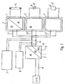
- Fig. 3 shows an embodiment of a control system according to the invention for a light-emitting device and provides a possible implementation of the circuit according to FIG. 1
- the system according to FIG. 3 In this case, a central unit 31 has, for example, a rectifier 32 for supplied AC line voltage 34 and a power factor correction circuit (PFC Power Factor Correction) 33 for reducing harmonics in the input current of the central unit 31.
- PFC Power Factor Correction power factor correction circuit
- the central unit provides a DC voltage on at least one connection on the output side.
- Over at least one DC output bus 37 are several operating device modules 40, 41, 42 connected to this DC output of the central unit 31.
- the operating device modules 40, 41 and 42 are configured in such a way that DC voltage is supplied to the input-side terminals by the central unit 31 or another operating device module and to output-side connections separated from the input-side connections to a further operating device, if applicable. Module loop the DC voltage.
- the operating device modules 40, 41, 42 to each other compatible inputs 43 and 44 outputs.
- these inputs and outputs are arranged on mutually applied sides of the housing of the modules and / or at a right angle to each other, but not on the same sides of the housing.
- the central unit can also control a plurality of output circuits in a star topology, to each of which several resource modules can be connected.
- a plurality of feeding central units control a common DC bus, whereby, for example, increases the interference and the load on a central unit is reduced.
- the operating device modules 40, 41, 42 may be provided for controlling different light sources. For this purpose, they also have a local control unit 35, 35 'or 35 "supplied by the DC output circuit 37.
- the resource module 40 supplies a gas discharge lamp 38 and the local control unit 35 is designed as an electronic ballast (ECG) with an inverter (DC / AC).
- ECG electronic ballast
- the electronic ballast can also control a group of parallel-connected gas discharge lamps together.
- the resource module 41 has a control unit 35 'which is designed to drive one or a group of light-emitting diodes 38'.
- the resource module 42 has a local control unit 35 '', which is suitable for driving a high-pressure lamp 38 ''.
- the local control units 35, 35 'and 35 "have the function of converting the supplied DC voltage from the bus 37 into an AC or DC voltage of predetermined amplitude, which is tuned to the needs of the respectively connected lighting means.
- the local control units 35, 35 'or 35' 'receive control commands via the bus 37 in the sense of a powerline system or else via further control inputs in order to bring the respectively connected lighting means into predetermined operating states or Queries status queries from the connected bulbs or their resources.
- the control commands, for example, from the central unit 31 can thus transmit predetermined input, output or dimming control values.
- the central processing unit or separate central controller comprises a poweline modulator and the resources corresponding to a powerline demodulator. If the communication is to take place bidirectionally via the bus 37, both mentioned communication partners have both a powerline modulator and a powerline demodulator.
- resource modules 40, 41 and 42 are connected to different types of light bulbs
- resource modules can be connected to the central unit 31, which supply at least partially bulbs of the same kind.
- a resource module with green bulbs, red bulbs and blue bulbs is connected to the central unit 31 for generating a colored light control.
- the bulbs are preferably LEDs.
- control commands for example from the central unit 31 to the local control units 35, 35 'or 35' ', it is thus possible to generate light mixing effects possibly also of a dynamic nature by corresponding transmission of dimming commands to the individual colors.
- the resource modules 40, 41 and 42 connected in the central unit 31 are electrically connected to the central unit 31 via the DC output bus 37.
- the resource modules 40, 41, 42 can also be connected mechanically, for example in the sense of a plug connection, either to the central unit 31 or to other similar equipment modules. It is advantageous that simultaneously with the plugging, ie the creation of the mechanical connection between a resource module and the central unit 31 and another resource module of the same type and the electrical contacting of the listed elements via the DC output bus 37 takes place.
- the electrical contact is preferably also via plug contacts, which can also be solved again.
- the housing of the resource modules on a surface male electrical connector elements and on a further surface corresponding male connector elements.
- the mechanical connection can also be created by other means, such as brackets, etc.
- the mechanical connections 39 are designed in particular as detachable mechanical connections in order to configure the illumination control system in a particularly flexible manner.
Landscapes
- Circuit Arrangement For Electric Light Sources In General (AREA)
Description
- Die vorliegende Erfindung bezieht sich auf die Steuerung von Leuchtmittel-Betriebsgeräten ausgehend von einer zentralen Einheit.
- Dabei geht die Erfindung von einem in
Fig. 2 schematisch dargestellten System aus. In diesem Beispiel ist das Leuchtmittel eine Gasentladungslampe 5, die von einem elektrischen Vorschaltgerät (EVG) 1 als Betriebsgerät angesteuert wird. In üblicher Weise weist dieses EVG 1 einen Gleichrichter mit Leistungsfaktor-Korrekturschaltung (PFC, Power Factor Correction) 2, einen Elektrolyt-Speicherkondensator 4 sowie einen HF-Wechselrichter 3 auf, der wiederum mittels über seinen Ausgangskreis 6 die Gasentladungslampe 5 ansteuert. Die Gleichspannung (Busspannung) liegt somit nur innerhalb des EVGs vor. - Zusätzlich kann eine Notbeleuchtungssteuerung 7 vorgesehen sein.
- Der Gleichrichter 2 in dem EVG 1 wird üblicherweise mit Wechselspannung 9, beispielsweise Netzspannung, versorgt.
- Gleichzeitig ist es bekannt, das EVG 1 über eine Digital-oder Analogbussteuerung 8 anzusteuern, um somit die Lampe 5 zu starten, zu dimmen oder auszuschalten. Festzuhalten ist, dass bei diesem Stand der Technik in jedem Lampenbetriebsgerät (EVG 1) ein eigener Gleichrichter 2 mit PFC-Schaltung vorgesehen ist. Eine derartige PFC-Schaltung verringert bekanntlich störende Oberwellen im Eingangsstrom. Andererseits stellen diese lokal in jedem EVG 1 vorgesehenen Wechselrichter mit PFC 2 einen beträchtlichen Kostenfaktor dar, der den Trend zu äußerst kostengünstig gefertigten EVG's stark eingrenzt.
- Aus der
GB 2 299 659 A - Ausgangspunkt und Aufgabe für die vorliegende Erfindung ist es dementsprechend, eine Ansteuerung für Leuchtmittel-Betriebsgeräte vorzuschlagen, die eine kostengünstigere Fertigung von Betriebsgeräten ermöglicht.
- Zentraler Punkt der Erfindung ist es dabei, dass die Einheit Gleichrichter/PFC nicht mehr lokal in jedem Betriebsgerät, sondern zentral für mehrere Betriebsgeräte vorgesehen ist. Die Verbindung zwischen dieser Zentrale, und den einzelnen Betriebsgeräten erfolgt erfindungsgemäß über einen DC-Ausgangskreis. Eine ähnliche Vorrichtung ist aus Patentschrift
US 5 485 057 (smallwood) bekannt. - Gleichzeitig soll trotz der zentralen Ausgestaltung eine flexible und auf die Bedürfnisse der angeschlossenen Betriebsgeräte angepasste Versorgung ermöglicht werden.
- Gemäß einem ersten Aspekt der vorliegenden Erfindung ist ein System zur Ansteuerung von Betriebsmitteln für Leuchtmittel vorgesehen, wobei das System eine Zentraleinheit aufweisend wenigstens einen Gleichrichter aufweist, der eine zugeführte Wechselspannung in eine Gleichspannung umsetzt und einer folgenden PFC-Schaltung zuführt. Weiterhin ist wenigstens ein Betriebsmittel-Modul vorgesehen, das mit der Zentraleinheit lösbar verbindbar ist. Dabei wird im Zuge einer mechanischen Verbindung des Betriebsmittel-Moduls mit der Zentraleinheit gleichzeitig auch das Betriebsmittel elektrisch mit dem Gleichspannungs-Ausgang der Zentraleinheit verbunden.
- Gemäß einem weiteren Aspekt der vorliegenden Erfindung ist ein derartiges System mit einer Zentraleinheit und wenigstens einem Betriebsmittel-Modul vorgesehen, wobei das Betriebsmittel-Modul derart ausgebildet ist, dass es durch Weiterschleifen eine ihm zugeführte DC-Versorgungsspannung wiederum an Anschlüssen für weitere Betriebsmittel-Module bereitstellt.
- Die Zentraleinheit kann dabei einen für sämtliche anschließbaren Betriebsmittel-Module gemeinsame Leistungsfaktor-Korrekturschaltung aufweisen.
- Betriebsmittel für unterschiedliche Typen an Leuchtmitteln können bereitgestellt werden, die sämtlich durch Weiterschleifen der DC-Versorgungsspannung versorgt werden. Betriebsmittel für LED Lampen ist aus Patentschrift
US 6 624 638 B2 (St-Germain) bekannt. - Andererseits können auch Betriebsmittel für Leuchtmittel gleichen Typs, aber unterschiedlicher Farbe bereitgestellt werden.
- Auf die DC-Versorgungsspannung können gemäß einer Powerline-Technik Befehlssignale aufmodulierbar sein. Die Zentraleinheit und/oder das Betriebsmittel-Modul weist in diesem Fall einen Powerline-Demodulator zum Auslesen der auf die DC-Versorgungsspannung aufmodulierten Befehlssignale auf. Eine ähnliche Modulations-Technik ist aus Patentschrift
EP 1 220 587 A2 (Setech) bekannt. - Weitere Merkmale, Vorteile und Eigenschaften der vorliegenden Erfindung sollen nunmehr unter Bezugnahme auf die Figuren der beigefügten Zeichnungen sowie die folgende detaillierte Beschreibung eines Ausführungsbeispieles näher erläutert werden.
- Fig. 1
- zeigt eine schematische Ansicht eines erfindungsgemäßen Steuersystems für Leuchtmittel-Betriebsgeräte mit zentraler Gleichrichter/PFC-Einheit und DC-Ausgangskreis,
- Fig. 2
- zeigt eine aus dem Stand der Technik bekannte Betriebsmittel-Ausgestaltung für Gasentladungslampen, und
- Fig. 3
- zeigt ein Ausführungsbeispiel der vorliegenden Erfindung, bei dem mehrere Leuchtmittel-Betriebsmodule auf eine zentrale Gleichrichter/PFC-Einheit aufgesetzt sind.
- Wie in
Fig. 1 gezeigt, ist eine Zentraleinheit, aufweisend beispielsweise einen Gleichrichter 2 sowie ggf. auch eine Leistungsfaktor-Korrekturschaltung (PFC) 10, gemeinsam für mehrere Leuchtmittel-Betriebsgeräte 1, 1', 1'' vorgesehen. Die Zentraleinheit 2 wird mit (Netz-) Wechselspannung 9 versorgt. - Wie in
Fig. 1 schematisch angedeutet, können die verschiedenen Leuchtmittel-Betriebsgeräte 1, 1', 1'' verschiedenste Leuchtmittel, wie beispielsweise eine Gasentladungslampe 5, Leuchtdioden 5', etc. ansteuern. Die Leuchtmittel selbst können dabei mit DC- oder mit AC-Spannung betrieben werden, wobei in letzerem Fall in dem zugehörigen Betriebsgerät ein Wechselrichter vorgesehen ist. - Weiterhin können an einen DC-Ausgangskreis 11 der Zentraleinheit auch andere (bspw. passive) lichttechnische oder gebäudetechnische Einrichtungen, wie beispielsweise ein Lichtsensor 5'' oder ein Bewegungsmelder (nicht dargestellt) angeschlossen sein.
- Je nach Natur der angeschlossenen Leuchtmittel 5, 5' bzw. Sensoren 5'' sind die Betriebsgeräte 1, 1', 1'' unterschiedlich ausgebildet. Für den Fall, dass eine Gasentladungslampe 5 angesteuert werden soll, ist das entsprechende Betriebsgerät 3 bspw. als elektronisches Vorschaltgerät (EVG) u.a. mit einem Wechselrichter ausgebildet. Die Betriebsgeräte können in diesem Fall auch als "Ausgangs-Konverter" bezeichnet werden.
- Die Spannungsversorgung der Betriebsgeräte und Leuchtmittel und optional auch die uni- oder bidirektionale Kommunikation zwischen der Zentraleinheit und den lokalen Betriebsgeräten 1, 1', 1'' erfolgt über wenigstens einen DC-Ausgangskreis 11, 12. Wie in
Fig. 1 schematisch dargestellt kann dabei ein Ausgangskreis 11 busartig bspw. mittels eines Paars gemeinsamer Busleitungen ausgestaltet sein, so dass ausgehend von diesem zentralen gemeinsamen Bus 11 die verschiedenen Betriebsgeräte 1, 1', 1'' über Stichleitungen 13, 13', 13'' versorgt werden. Alternativ oder zusätzlich können für einzelne Betriebsgeräte bzw. gemeinsam versorgte Gruppen an Betriebsgeräten individuelle Ausgangskreise 12 vorgesehen sein. - Dieser DC-Ausgangskreis hat den Vorteil, dass er im Vergleich zu entsprechenden AC-Kreisen weniger anfällig gegenüber parasitären Effekten ist.
- Festzuhalten ist, dass gemäß der vorliegenden Erfindung die Zentraleinheit für mehrere Betriebsgeräte gemeinsam vorgesehen ist, wobei die Zentraleinheit mit den Betriebsgeräten mittels wenigstens einem DC-Ausgangskreis verbunden ist.
-
Fig. 3 zeigt ein Ausführungsbeispiel eines erfindungsgemäßen Steuersystems für ein Leuchtmittel-Betriebsgerät und stellt eine mögliche Implementierung der Schaltung gemässFigur 1 dar. Das System gemässFigur 3 weist dabei eine Zentraleinheit 31 auf, die beispielsweise einen Gleichrichter 32 für zugeführte Netz-Wechselspannung 34 sowie eine Leistungsfaktor-Korrekturschaltung (PFC Power Factor Correction) 33 zur Verringerung von Oberwellen im Eingangsstrom der Zentraleinheit 31 aufweist. - Die Zentraleinheit stellt ausgangsseitig an wenigstens einem Anschluss eine DC-Spannung bereit. Über wenigstens einen DC-Ausgangsbus 37 sind mehrere Betriebsgerät-Module 40, 41, 42 mit diesem DC-Ausgang der Zentraleinheit 31 verbunden. Die Betriebsgerät-Module 40, 41 und 42 sind dabei derart ausgestaltet, dass an eingangsseitigen Anschlüssen DC-Spannung von der Zentraleinheit 31 bzw. einem weiteren Betriebsgerät-Modul zugeführt bekommen und an von den eingangsseitigen Anschlüssen getrennten ausgangsseitigen Anschlüssen an ein ggf. weiteres Betriebsgerät-Modul die DC-Spannung weiterschleifen. Im dargestellten Ausführungsbeispiel weisen die Betriebsgerät-Module 40, 41, 42 dazu miteinander kompatible Eingänge 43 bzw. Ausgänge 44 auf. Vorzugsweise sind diese Eingänge und Ausgänge an voneinander angewandten Seiten des Gehäuses der Module und/oder in einem rechten Winkel zueinander, aber nicht an gleichen Seiten des Gehäuses angeordnet.
- Die Zentraleinheit kann auch in eienr Sterntopologie mehrere Ausgangskreise ansteuern, an denen jeweils mehrere Betriebsmittel-Module angeschlossen werden können.
- Es kann auch vorgesehen sein, dass mehrere einspeisende Zentraleinheiten einen gemeinsamen DC-Bus ansteuern, wodurch bspw. die Störsicherheit erhöht und die Belastung einer Zentraleinheit verringert wird.
- Die Betriebsgerät-Module 40, 41, 42 können zur Ansteuerung unterschiedlicher Leuchtmittel vorgesehen sein. Dazu weisen sie entsprechend auch eine von dem DC-Ausgangskreis 37 her versorgte lokale Steuereinheit 35, 35' bzw. 35'' auf.
- Im dargestellten Beispiel versorgt das Betriebsmittel-Modul 40 eine Gasentladungslampe 38 und die lokale Steuereinheit 35 ist als elektronisches Vorschaltgerät (EVG) mit Wechselrichter (DC/AC) ausgebildet. Das EVG kann auch eine Gruppe parallel geschalteter Gasentladungslampen gemeinsam ansteuern.
- Das Betriebsmittel-Modul 41 weist eine Steuereinheit 35' auf, die zur Ansteuerung von einer bzw. einer Gruppe von Leuchtdioden 38' ausgebildet ist.
- Schließlich weist das Betriebsmittel-Modul 42 eine lokale Steuereinheit 35'' auf, die zur Ansteuerung einer Hochdrucklampe 38'' geeignet ist.
- Allgemein weisen die lokalen Steuereinheiten 35, 35' und 35'' die Funktion auf, die zugeführte DC-Spannung von dem Bus 37 in eine AC- oder DC-Spannung vorgegebener Amplitude umzusetzen, die auf die Bedürfnisse der jeweils angeschlossenen Leuchtmittel abgestimmt ist.
- Zusätzlich kann es vorgesehen sein, dass die lokalen Steuereinheiten 35, 35' bzw. 35'' über den Bus 37 im Sinne eines Powerline-Systems oder aber auch über weitere Steuereingänge Ansteuerbefehle entgegennehmen, um die jeweils angeschlossenen Leuchtmittel in vorbestimmte Betriebszustände zu bringen bzw. Statusabfragen von den angeschlossenen Leuchtmitteln bzw. deren Betriebsmitteln abzufragen. Die Ansteuerbefehle beispielsweise von der Zentraleinheit 31 können also vorbestimmte Ein-, Aus- oder Dimm-Stellwerte übermitteln.
- Wenn die Befehlre über den DC-Bus 37 übermittelt werden, weist die Zentraleinheit oder eine separate zentrale Steuerung einen Poweline-Modulator und die Betriebsmittel entsprechend einen Powerline-Demodulator auf. Fall die Kommunikation bidirektional über den Bus 37 erfolgen soll, weisen beide genannten Kommunikationspartner sowohl einen Powerline-Modulator wie auch einen Powerline-Demodulator auf.
- Auch wenn in dem Ausführungsbeispiel von
Fig. 3 dargestellt ist, dass an jedes der an der Zentraleinheit 31 angeschlossenen Betriebsmittel-Module 40, 41 bzw. 42 Leuchtmittel unterschiedlichen Typs angeschlossen sind, können natürlich auch Betriebsmittel-Module an die Zentraleinheit 31 angeschlossen werden, die zumindest teilweise Leuchtmittel gleicher Art versorgen. Vorstellbar ist z.B., dass an die Zentraleinheit 31 zur Erzeugung einer farbigen Lichtsteuerung je ein Betriebsmittel-Modul mit grünen Leuchtmitteln, roten Leuchtmitteln und blauen Leuchtmitteln angeschlossen ist. In diesem Fall sind die Leuchtmittel vorzugsweise LEDs. - Über die oben angeführten Steuerbefehle beispielsweise von der Zentraleinheit 31 an die lokalen Steuereinheiten 35, 35' bzw. 35'' können somit Lichtmischeffekte ggf. auch dynamischer Art durch entsprechende Übermittlung von Dimmbefehlen an die einzelnen Farben erzeugt werden.
- Wie im obigen Abschnitt ausgeführt, sind also die in der Zentraleinheit 31 angeschlossenen Betriebsmittelmodule 40, 41 bzw. 42 elektrisch mit der Zentraleinheit 31 über den DC-Ausgangsbus 37 verbunden.
- Wie schematisch durch das Bezugszeichen 39 dargestellt ist, können die Betriebsmittel-Module 40, 41, 42 auch mechanisch, beispielsweise im Sinne einer Steckverbindung entweder mit der Zentraleinheit 31 oder aber mit weiteren gleichartigen Betriebsmitteln-Modulen verbunden werden. Vorteilhaft ist dabei, dass gleichzeitig mit dem Aufstecken, d.h. dem Schaffen der mechanischen Verbindung zwischen einem Betriebsmittel-Modul und der Zentraleinheit 31 bzw. einem weiteren Betriebsmittel-Modul gleicher Art auch die elektrische Kontaktierung der angeführten Elemente über den DC-Ausgangsbus 37 erfolgt. Die elektrische Kontaktierung erfolgt dabei vorzugsweise ebenfalls über Steckkontakte, die auch wieder gelöst werden können. In diesem Fall weisen die Gehäuse der Betriebsmittel-Module auf einer Fläche männliche elektrische Steckerelemente und auf einer weiteren Fläche korrespondierende männliche Steckerelemente auf.
- Die mechanische Verbindung kann auch über andere Mittel, wie bspw. Klammern etc. geschaffen werden.
- Die mechanischen Verbindungen 39 sind insbesondere als lösbare mechanische Verbindungen ausgeführt, um das Beleuchtungs-Ansteuersystem besonders flexibel auszugestalten.
Claims (5)
- System zur Ansteuerung von Betriebsmitteln für Leuchtmittel, aufweisend:- eine Zentraleinheit (31) aufweisend wenigstens einen Gleichrichter (32), der eine zugeführte Wechselspannung (34) in eine Gleichspannung umsetzt, die einer folgenden Leistungsfaktor-Korrekturschaltung (PFC) zugeführt ist, der einen Gleichspannungs-Ausgang (36) der Zentraleinheit (31) versorgt, und- wenigstens ein Betriebsmittel-Modul (40, 41, 42), das mit der Zentraleinheit (31) lösbar verbindbar ist, wobei im Zuge einer mechanischen Verbindung des Betriebsmittel-Moduls (40, 41, 42) mit der Zentraleinheit (31) gleichzeitig auch das Betriebsmittel-Modul (40, 41, 42) elektrisch mit dem Gleichspannungs-Ausgang (36) der Zentraleinheit (31) verbindbar ist, dadurch gekennzeichnet dass wenigstens ein Betriebsmittel-Modul (40, 41, 42) ein Treibermodul für mindestens eine LED ist,wobei auf die DC-Versorgungsspannung gemäß einer Powerline-Technik Befehlssignale aufmodulierbar sind und die Zentraleinheit (31) und/oder das Betriebsmittel-Modul (40, 41, 42) einen Powerline-Demodulator zum Auslesen der auf die DC-Versorgungsspannung aufmodulierten Befehlssignale aufweist.
- System nach Anspruch 1,
wobei das Betriebsmittel-Modul (40, 41, 42) derart ausgebildet ist, dass es durch Weiterschleifen eine ihm zugeführte DC-Versorgungsspannung wiederum an Anschlüssen (44) für weitere Betriebsmittel-Module (41) bereitstellt. - System nach einem der vorhergehenden Ansprüche,
dadurch gekennzeichnet,
dass Betriebsmittel-Module (40, 41, 42) für unterschiedliche Typen an Leuchtmitteln (38, 38', 38'') bereitgestellt werden, die durch Weiterschleifen der DC-Versorgungsspannung versorgt werden. - System nach einem der vorhergehenden Ansprüche,
dadurch gekennzeichnet,
dass Betriebmittel-Module für Leuchtmittel gleichen Typs, aber unterschiedlicher Farbe bereitgestellt werden, die durch Weiterschleifen der DC-Versorgungsspannung versorgt werden. - System nach einem der vorhergehenden Anprüche,
dadurch gekennzeichnet,
dass die Betriebsmittel-Module (40, 41, 42) für Leuchtmittel (38, 38', 38'') unterschiedlicher Farbe ausgebildet sind.
Priority Applications (1)
| Application Number | Priority Date | Filing Date | Title |
|---|---|---|---|
| EP08155030.3A EP1947913B1 (de) | 2004-01-14 | 2004-11-30 | DC-versorgte Betriebsmittel-Module für Leuchtmittel |
Applications Claiming Priority (2)
| Application Number | Priority Date | Filing Date | Title |
|---|---|---|---|
| DE102004002018 | 2004-01-14 | ||
| DE200410002018 DE102004002018A1 (de) | 2004-01-14 | 2004-01-14 | DC-versorgte Betriebsmittel-Module für Leuchtmittel |
Related Child Applications (2)
| Application Number | Title | Priority Date | Filing Date |
|---|---|---|---|
| EP08155030.3A Division EP1947913B1 (de) | 2004-01-14 | 2004-11-30 | DC-versorgte Betriebsmittel-Module für Leuchtmittel |
| EP08155030.3A Division-Into EP1947913B1 (de) | 2004-01-14 | 2004-11-30 | DC-versorgte Betriebsmittel-Module für Leuchtmittel |
Publications (2)
| Publication Number | Publication Date |
|---|---|
| EP1555860A1 EP1555860A1 (de) | 2005-07-20 |
| EP1555860B1 true EP1555860B1 (de) | 2016-05-25 |
Family
ID=34609550
Family Applications (2)
| Application Number | Title | Priority Date | Filing Date |
|---|---|---|---|
| EP08155030.3A Expired - Lifetime EP1947913B1 (de) | 2004-01-14 | 2004-11-30 | DC-versorgte Betriebsmittel-Module für Leuchtmittel |
| EP04028344.2A Expired - Lifetime EP1555860B1 (de) | 2004-01-14 | 2004-11-30 | DC-versorgte Betriebsmittel-Module für Leuchtmittel |
Family Applications Before (1)
| Application Number | Title | Priority Date | Filing Date |
|---|---|---|---|
| EP08155030.3A Expired - Lifetime EP1947913B1 (de) | 2004-01-14 | 2004-11-30 | DC-versorgte Betriebsmittel-Module für Leuchtmittel |
Country Status (2)
| Country | Link |
|---|---|
| EP (2) | EP1947913B1 (de) |
| DE (1) | DE102004002018A1 (de) |
Families Citing this family (16)
| Publication number | Priority date | Publication date | Assignee | Title |
|---|---|---|---|---|
| US7746877B2 (en) * | 2007-04-26 | 2010-06-29 | 2Wire, Inc. | Method and apparatus for communicating loss of alternating current power supply |
| WO2011087685A1 (en) * | 2010-01-13 | 2011-07-21 | Masco Corporation | Low voltage control systems and associated methods |
| WO2011087684A1 (en) * | 2010-01-13 | 2011-07-21 | Masco Corporation | Low voltage control systems and associated methods |
| DE102010031247A1 (de) * | 2010-03-19 | 2011-09-22 | Tridonic Ag | Niedervolt-Spannungsversorgung für ein LED-Beleuchtungssystem |
| DE102010031230A1 (de) * | 2010-03-19 | 2011-09-22 | Tridonic Ag | Modulares LED-Beleuchtungssystem mit internem Bus |
| DE102010031244B4 (de) * | 2010-03-19 | 2023-01-12 | Tridonic Ag | Modulares LED-Beleuchtungssystem |
| DE102010003797A1 (de) * | 2010-04-09 | 2011-10-13 | Tridonic Ag | Modulares LED-Beleuchtungssystem mit Notlichtfunktion |
| DE102010003799A1 (de) * | 2010-04-09 | 2011-12-15 | Tridonic Ag | Modulares LED-Beleuchtungssystem mit Notlichtfunktion |
| CA2801924A1 (en) * | 2010-06-09 | 2011-12-15 | Clear-Vu Lighting Llc | Led task lighting system |
| DE102010046893A1 (de) * | 2010-09-29 | 2012-03-29 | E:Cue Control Gmbh | Bedienvorrichtung zur Ansteuerung einer mehrfarbigen Lichtquelle und Beleuchtungsvorrichtung |
| CN102612220A (zh) * | 2012-02-29 | 2012-07-25 | 浙江师范大学 | 一种复用总线式led照明系统控制方法 |
| WO2014147512A1 (en) | 2013-03-20 | 2014-09-25 | Koninklijke Philips N.V. | Dc power distribution system |
| WO2014174159A1 (fr) | 2013-04-24 | 2014-10-30 | Societe D'etudes Et D'economies En Eclairage, Se3 | Dispositif d'alimentation en courant continu d'un ensemble de dispositifs d'éclairage à leds utilisés dans l'éclairage industriel et l'éclairage tertiaire |
| DE102013220965A1 (de) * | 2013-10-16 | 2015-04-16 | Tridonic Gmbh & Co Kg | Verfahren und Vorrichtungen zur Kommunikation in einem Beleuchtungssystem |
| NL2021705B1 (en) | 2018-09-25 | 2020-05-07 | Schreder Sa | Multi-protocol luminaire system |
| EP3843240B2 (de) * | 2019-12-23 | 2026-04-29 | Zumtobel Lighting GmbH | Zentraleinheit zur versorgung von notbeleuchtungsmitteln auf einem gleichstrombus |
Citations (3)
| Publication number | Priority date | Publication date | Assignee | Title |
|---|---|---|---|---|
| US6510995B2 (en) * | 2001-03-16 | 2003-01-28 | Koninklijke Philips Electronics N.V. | RGB LED based light driver using microprocessor controlled AC distributed power system |
| US6570505B1 (en) * | 1997-12-30 | 2003-05-27 | Gelcore Llc | LED lamp with a fault-indicating impedance-changing circuit |
| US6624638B2 (en) * | 1999-11-19 | 2003-09-23 | Gelcore, Llc | Method and device for remote monitoring of LED lamps |
Family Cites Families (12)
| Publication number | Priority date | Publication date | Assignee | Title |
|---|---|---|---|---|
| US6144445A (en) * | 1980-08-14 | 2000-11-07 | Nilssen; Ole K. | Electronic ballast products and systems |
| DE3212339A1 (de) * | 1982-03-12 | 1983-09-22 | Manfred 4350 Recklinghausen Frankauer | Beleuchtungsanlage, insbesondere fuer den einsatz im bergbau untertage |
| US4751398A (en) * | 1986-03-18 | 1988-06-14 | The Bodine Company | Lighting system for normal and emergency operation of high intensity discharge lamps |
| US5367229A (en) * | 1991-03-28 | 1994-11-22 | Yang Thien S | Lamp ballasts |
| AU6908894A (en) * | 1993-05-13 | 1994-12-12 | Etta Industries, Inc. | System and method for distributing power to gas discharge lamps |
| US5485057A (en) * | 1993-09-02 | 1996-01-16 | Smallwood; Robert C. | Gas discharge lamp and power distribution system therefor |
| GB2299659A (en) * | 1995-04-03 | 1996-10-09 | Solar Wide Ind Ltd | Lighting systems |
| DE29622825U1 (de) * | 1996-03-29 | 1997-07-10 | Lohmann-Werke GmbH & Co, 33604 Bielefeld | Bestrahlungsgerät |
| FR2761564B1 (fr) * | 1997-03-27 | 2001-07-27 | Jacques Emile Boudan | Systeme et appareil d'alimentation des lampes a decharge d'un reseau d'eclairage |
| FR2804572B1 (fr) * | 2000-02-01 | 2002-04-19 | Dev Ind Et Commercial D Aldim | Dispositif generateur a moyenne frequence pour alimenter une lampe a decharge |
| TW473000U (en) * | 2000-09-21 | 2002-01-11 | Yung-Chiuan Lin | Circuit structure improvement of fluorescence lamp |
| IT1316561B1 (it) * | 2000-12-28 | 2003-04-22 | Setech S R L | Dispositivo di alimentazione di lampade a sarica a catodo freddo. |
-
2004
- 2004-01-14 DE DE200410002018 patent/DE102004002018A1/de not_active Withdrawn
- 2004-11-30 EP EP08155030.3A patent/EP1947913B1/de not_active Expired - Lifetime
- 2004-11-30 EP EP04028344.2A patent/EP1555860B1/de not_active Expired - Lifetime
Patent Citations (3)
| Publication number | Priority date | Publication date | Assignee | Title |
|---|---|---|---|---|
| US6570505B1 (en) * | 1997-12-30 | 2003-05-27 | Gelcore Llc | LED lamp with a fault-indicating impedance-changing circuit |
| US6624638B2 (en) * | 1999-11-19 | 2003-09-23 | Gelcore, Llc | Method and device for remote monitoring of LED lamps |
| US6510995B2 (en) * | 2001-03-16 | 2003-01-28 | Koninklijke Philips Electronics N.V. | RGB LED based light driver using microprocessor controlled AC distributed power system |
Also Published As
| Publication number | Publication date |
|---|---|
| EP1947913A1 (de) | 2008-07-23 |
| EP1555860A1 (de) | 2005-07-20 |
| EP1947913B1 (de) | 2017-05-24 |
| DE102004002018A1 (de) | 2005-08-04 |
Similar Documents
| Publication | Publication Date | Title |
|---|---|---|
| EP1555860B1 (de) | DC-versorgte Betriebsmittel-Module für Leuchtmittel | |
| EP1555859B1 (de) | Ansteuerung von Leuchtmittel-Betriebsgeräten über einen modulierten DC-Bus | |
| EP2510747B1 (de) | Steuerbare retrofit led-lampen und beleuchtungssystem mit led-lampe | |
| DE202008002883U1 (de) | Schaltung zur Ansteuerung mindestens einer Leuchteinheit und Leuchte | |
| EP1843641B1 (de) | Steuerung von Betriebsgeräten für Leuchtmittel mittels Schaltmodulation eines DC-Busses | |
| EP2280585B1 (de) | Verfahren zur Einstellung der Ansteuerung mehrerer Leuchten | |
| EP2319278A2 (de) | Verfahren zur ansteuerung für ein betriebsgerät für leuchtmittel, insbesondere led | |
| EP2629589A2 (de) | System zur Akzentbeleuchtung oder zur Erzeugung von Leuchteffekten sowie Verfahren zum Betreiben eines entsprechenden Systems | |
| EP2282610B1 (de) | Verfahren zur Ansteuerung einer Leuchte | |
| EP2278861B1 (de) | Zentrale Versorgung über mehrere DC-Ausgangskreise | |
| EP2365737B1 (de) | Zentraler PFC mit DC-Ausgangskreisregelung | |
| EP3031299A2 (de) | Dimmbare led-leuchtmittelstrecke | |
| WO2011041816A1 (de) | Schnittstelle für ein betriebsgerät für leuchtmittel | |
| DE19824756A1 (de) | Helligkeitssteuerung für Leuchtmittel | |
| EP2484181A1 (de) | Schnittstelle für ein betriebsgerät für leuchtmittel | |
| WO2011106814A2 (de) | Betriebsgerät für leuchtmittel | |
| EP1442635A1 (de) | Parallel zuschaltbare evgs aufgrund des lampentyps | |
| DE102009051738A1 (de) | Notbeleuchtungsgerät mit LED | |
| AT519952B1 (de) | Gegentaktwandler mit einem Spannungsausgang zur dimmbaren Versorgung eines LED-Moduls | |
| DE102024112096A1 (de) | Betriebsgerät für ein leuchtmittel, sensormodul für eine leuchte und leuchte | |
| EP2651191A1 (de) | Modul zum Ansteuern einer Leuchte |
Legal Events
| Date | Code | Title | Description |
|---|---|---|---|
| PUAI | Public reference made under article 153(3) epc to a published international application that has entered the european phase |
Free format text: ORIGINAL CODE: 0009012 |
|
| AK | Designated contracting states |
Kind code of ref document: A1 Designated state(s): AT BE BG CH CY CZ DE DK EE ES FI FR GB GR HU IE IS IT LI LU MC NL PL PT RO SE SI SK TR |
|
| AX | Request for extension of the european patent |
Extension state: AL HR LT LV MK YU |
|
| 17P | Request for examination filed |
Effective date: 20051019 |
|
| AKX | Designation fees paid |
Designated state(s): AT BE BG CH CY CZ DE DK EE ES FI FR GB GR HU IE IS IT LI LU MC NL PL PT RO SE SI SK TR |
|
| 17Q | First examination report despatched |
Effective date: 20070129 |
|
| RAP1 | Party data changed (applicant data changed or rights of an application transferred) |
Owner name: TRIDONIC GMBH & CO KG |
|
| GRAP | Despatch of communication of intention to grant a patent |
Free format text: ORIGINAL CODE: EPIDOSNIGR1 |
|
| INTG | Intention to grant announced |
Effective date: 20151223 |
|
| GRAS | Grant fee paid |
Free format text: ORIGINAL CODE: EPIDOSNIGR3 |
|
| GRAA | (expected) grant |
Free format text: ORIGINAL CODE: 0009210 |
|
| AK | Designated contracting states |
Kind code of ref document: B1 Designated state(s): AT BE BG CH CY CZ DE DK EE ES FI FR GB GR HU IE IS IT LI LU MC NL PL PT RO SE SI SK TR |
|
| REG | Reference to a national code |
Ref country code: GB Ref legal event code: FG4D Free format text: NOT ENGLISH |
|
| REG | Reference to a national code |
Ref country code: CH Ref legal event code: EP |
|
| REG | Reference to a national code |
Ref country code: IE Ref legal event code: FG4D Free format text: LANGUAGE OF EP DOCUMENT: GERMAN Ref country code: AT Ref legal event code: REF Ref document number: 803253 Country of ref document: AT Kind code of ref document: T Effective date: 20160615 |
|
| REG | Reference to a national code |
Ref country code: DE Ref legal event code: R096 Ref document number: 502004015203 Country of ref document: DE |
|
| REG | Reference to a national code |
Ref country code: NL Ref legal event code: MP Effective date: 20160525 |
|
| PG25 | Lapsed in a contracting state [announced via postgrant information from national office to epo] |
Ref country code: NL Free format text: LAPSE BECAUSE OF FAILURE TO SUBMIT A TRANSLATION OF THE DESCRIPTION OR TO PAY THE FEE WITHIN THE PRESCRIBED TIME-LIMIT Effective date: 20160525 Ref country code: FI Free format text: LAPSE BECAUSE OF FAILURE TO SUBMIT A TRANSLATION OF THE DESCRIPTION OR TO PAY THE FEE WITHIN THE PRESCRIBED TIME-LIMIT Effective date: 20160525 |
|
| REG | Reference to a national code |
Ref country code: FR Ref legal event code: PLFP Year of fee payment: 13 |
|
| PG25 | Lapsed in a contracting state [announced via postgrant information from national office to epo] |
Ref country code: GR Free format text: LAPSE BECAUSE OF FAILURE TO SUBMIT A TRANSLATION OF THE DESCRIPTION OR TO PAY THE FEE WITHIN THE PRESCRIBED TIME-LIMIT Effective date: 20160826 Ref country code: SE Free format text: LAPSE BECAUSE OF FAILURE TO SUBMIT A TRANSLATION OF THE DESCRIPTION OR TO PAY THE FEE WITHIN THE PRESCRIBED TIME-LIMIT Effective date: 20160525 Ref country code: PT Free format text: LAPSE BECAUSE OF FAILURE TO SUBMIT A TRANSLATION OF THE DESCRIPTION OR TO PAY THE FEE WITHIN THE PRESCRIBED TIME-LIMIT Effective date: 20160926 Ref country code: ES Free format text: LAPSE BECAUSE OF FAILURE TO SUBMIT A TRANSLATION OF THE DESCRIPTION OR TO PAY THE FEE WITHIN THE PRESCRIBED TIME-LIMIT Effective date: 20160525 |
|
| PG25 | Lapsed in a contracting state [announced via postgrant information from national office to epo] |
Ref country code: IT Free format text: LAPSE BECAUSE OF FAILURE TO SUBMIT A TRANSLATION OF THE DESCRIPTION OR TO PAY THE FEE WITHIN THE PRESCRIBED TIME-LIMIT Effective date: 20160525 |
|
| PG25 | Lapsed in a contracting state [announced via postgrant information from national office to epo] |
Ref country code: RO Free format text: LAPSE BECAUSE OF FAILURE TO SUBMIT A TRANSLATION OF THE DESCRIPTION OR TO PAY THE FEE WITHIN THE PRESCRIBED TIME-LIMIT Effective date: 20160525 Ref country code: EE Free format text: LAPSE BECAUSE OF FAILURE TO SUBMIT A TRANSLATION OF THE DESCRIPTION OR TO PAY THE FEE WITHIN THE PRESCRIBED TIME-LIMIT Effective date: 20160525 Ref country code: CZ Free format text: LAPSE BECAUSE OF FAILURE TO SUBMIT A TRANSLATION OF THE DESCRIPTION OR TO PAY THE FEE WITHIN THE PRESCRIBED TIME-LIMIT Effective date: 20160525 Ref country code: DK Free format text: LAPSE BECAUSE OF FAILURE TO SUBMIT A TRANSLATION OF THE DESCRIPTION OR TO PAY THE FEE WITHIN THE PRESCRIBED TIME-LIMIT Effective date: 20160525 Ref country code: SK Free format text: LAPSE BECAUSE OF FAILURE TO SUBMIT A TRANSLATION OF THE DESCRIPTION OR TO PAY THE FEE WITHIN THE PRESCRIBED TIME-LIMIT Effective date: 20160525 |
|
| PG25 | Lapsed in a contracting state [announced via postgrant information from national office to epo] |
Ref country code: PL Free format text: LAPSE BECAUSE OF FAILURE TO SUBMIT A TRANSLATION OF THE DESCRIPTION OR TO PAY THE FEE WITHIN THE PRESCRIBED TIME-LIMIT Effective date: 20160525 Ref country code: BE Free format text: LAPSE BECAUSE OF NON-PAYMENT OF DUE FEES Effective date: 20161130 |
|
| PGFP | Annual fee paid to national office [announced via postgrant information from national office to epo] |
Ref country code: AT Payment date: 20161125 Year of fee payment: 13 |
|
| REG | Reference to a national code |
Ref country code: DE Ref legal event code: R097 Ref document number: 502004015203 Country of ref document: DE |
|
| PLBE | No opposition filed within time limit |
Free format text: ORIGINAL CODE: 0009261 |
|
| STAA | Information on the status of an ep patent application or granted ep patent |
Free format text: STATUS: NO OPPOSITION FILED WITHIN TIME LIMIT |
|
| 26N | No opposition filed |
Effective date: 20170228 |
|
| PG25 | Lapsed in a contracting state [announced via postgrant information from national office to epo] |
Ref country code: SI Free format text: LAPSE BECAUSE OF FAILURE TO SUBMIT A TRANSLATION OF THE DESCRIPTION OR TO PAY THE FEE WITHIN THE PRESCRIBED TIME-LIMIT Effective date: 20160525 |
|
| REG | Reference to a national code |
Ref country code: CH Ref legal event code: PL |
|
| PG25 | Lapsed in a contracting state [announced via postgrant information from national office to epo] |
Ref country code: CH Free format text: LAPSE BECAUSE OF NON-PAYMENT OF DUE FEES Effective date: 20161130 Ref country code: LI Free format text: LAPSE BECAUSE OF NON-PAYMENT OF DUE FEES Effective date: 20161130 |
|
| REG | Reference to a national code |
Ref country code: IE Ref legal event code: MM4A |
|
| PG25 | Lapsed in a contracting state [announced via postgrant information from national office to epo] |
Ref country code: LU Free format text: LAPSE BECAUSE OF NON-PAYMENT OF DUE FEES Effective date: 20161130 |
|
| REG | Reference to a national code |
Ref country code: FR Ref legal event code: PLFP Year of fee payment: 14 |
|
| PG25 | Lapsed in a contracting state [announced via postgrant information from national office to epo] |
Ref country code: IE Free format text: LAPSE BECAUSE OF NON-PAYMENT OF DUE FEES Effective date: 20161130 |
|
| REG | Reference to a national code |
Ref country code: BE Ref legal event code: MM Effective date: 20161130 |
|
| PG25 | Lapsed in a contracting state [announced via postgrant information from national office to epo] |
Ref country code: CY Free format text: LAPSE BECAUSE OF FAILURE TO SUBMIT A TRANSLATION OF THE DESCRIPTION OR TO PAY THE FEE WITHIN THE PRESCRIBED TIME-LIMIT Effective date: 20160525 Ref country code: HU Free format text: LAPSE BECAUSE OF FAILURE TO SUBMIT A TRANSLATION OF THE DESCRIPTION OR TO PAY THE FEE WITHIN THE PRESCRIBED TIME-LIMIT; INVALID AB INITIO Effective date: 20041130 |
|
| PG25 | Lapsed in a contracting state [announced via postgrant information from national office to epo] |
Ref country code: IS Free format text: LAPSE BECAUSE OF FAILURE TO SUBMIT A TRANSLATION OF THE DESCRIPTION OR TO PAY THE FEE WITHIN THE PRESCRIBED TIME-LIMIT Effective date: 20160525 Ref country code: TR Free format text: LAPSE BECAUSE OF FAILURE TO SUBMIT A TRANSLATION OF THE DESCRIPTION OR TO PAY THE FEE WITHIN THE PRESCRIBED TIME-LIMIT Effective date: 20160525 Ref country code: MC Free format text: LAPSE BECAUSE OF FAILURE TO SUBMIT A TRANSLATION OF THE DESCRIPTION OR TO PAY THE FEE WITHIN THE PRESCRIBED TIME-LIMIT Effective date: 20160525 |
|
| REG | Reference to a national code |
Ref country code: AT Ref legal event code: MM01 Ref document number: 803253 Country of ref document: AT Kind code of ref document: T Effective date: 20171130 |
|
| PG25 | Lapsed in a contracting state [announced via postgrant information from national office to epo] |
Ref country code: BG Free format text: LAPSE BECAUSE OF FAILURE TO SUBMIT A TRANSLATION OF THE DESCRIPTION OR TO PAY THE FEE WITHIN THE PRESCRIBED TIME-LIMIT Effective date: 20160525 |
|
| PG25 | Lapsed in a contracting state [announced via postgrant information from national office to epo] |
Ref country code: AT Free format text: LAPSE BECAUSE OF NON-PAYMENT OF DUE FEES Effective date: 20171130 |
|
| REG | Reference to a national code |
Ref country code: DE Ref legal event code: R084 Ref document number: 502004015203 Country of ref document: DE |
|
| PGFP | Annual fee paid to national office [announced via postgrant information from national office to epo] |
Ref country code: BG Payment date: 20181128 Year of fee payment: 12 |
|
| PGFP | Annual fee paid to national office [announced via postgrant information from national office to epo] |
Ref country code: GB Payment date: 20191128 Year of fee payment: 16 |
|
| PG25 | Lapsed in a contracting state [announced via postgrant information from national office to epo] |
Ref country code: FR Free format text: LAPSE BECAUSE OF NON-PAYMENT OF DUE FEES Effective date: 20191130 |
|
| GBPC | Gb: european patent ceased through non-payment of renewal fee |
Effective date: 20201130 |
|
| PG25 | Lapsed in a contracting state [announced via postgrant information from national office to epo] |
Ref country code: GB Free format text: LAPSE BECAUSE OF NON-PAYMENT OF DUE FEES Effective date: 20201130 |
|
| PGFP | Annual fee paid to national office [announced via postgrant information from national office to epo] |
Ref country code: DE Payment date: 20220527 Year of fee payment: 19 |
|
| P01 | Opt-out of the competence of the unified patent court (upc) registered |
Effective date: 20230530 |
|
| REG | Reference to a national code |
Ref country code: DE Ref legal event code: R119 Ref document number: 502004015203 Country of ref document: DE |
|
| PG25 | Lapsed in a contracting state [announced via postgrant information from national office to epo] |
Ref country code: DE Free format text: LAPSE BECAUSE OF NON-PAYMENT OF DUE FEES Effective date: 20240601 |
|
| PG25 | Lapsed in a contracting state [announced via postgrant information from national office to epo] |
Ref country code: DE Free format text: LAPSE BECAUSE OF NON-PAYMENT OF DUE FEES Effective date: 20240601 |