EP1556586B1 - Verfahren und vorrichtung zur regenerierung eines partikelfilters für abgasleitungen, und geeigneter partikelfilter - Google Patents
Verfahren und vorrichtung zur regenerierung eines partikelfilters für abgasleitungen, und geeigneter partikelfilter Download PDFInfo
- Publication number
- EP1556586B1 EP1556586B1 EP03780238A EP03780238A EP1556586B1 EP 1556586 B1 EP1556586 B1 EP 1556586B1 EP 03780238 A EP03780238 A EP 03780238A EP 03780238 A EP03780238 A EP 03780238A EP 1556586 B1 EP1556586 B1 EP 1556586B1
- Authority
- EP
- European Patent Office
- Prior art keywords
- reactor
- solid compound
- compound
- particulate filter
- exhaust line
- Prior art date
- Legal status (The legal status is an assumption and is not a legal conclusion. Google has not performed a legal analysis and makes no representation as to the accuracy of the status listed.)
- Expired - Lifetime
Links
Images


Classifications
-
- F—MECHANICAL ENGINEERING; LIGHTING; HEATING; WEAPONS; BLASTING
- F01—MACHINES OR ENGINES IN GENERAL; ENGINE PLANTS IN GENERAL; STEAM ENGINES
- F01N—GAS-FLOW SILENCERS OR EXHAUST APPARATUS FOR MACHINES OR ENGINES IN GENERAL; GAS-FLOW SILENCERS OR EXHAUST APPARATUS FOR INTERNAL-COMBUSTION ENGINES
- F01N3/00—Exhaust or silencing apparatus having means for purifying, rendering innocuous, or otherwise treating exhaust
- F01N3/02—Exhaust or silencing apparatus having means for purifying, rendering innocuous, or otherwise treating exhaust for cooling, or for removing solid constituents of, exhaust
- F01N3/021—Exhaust or silencing apparatus having means for purifying, rendering innocuous, or otherwise treating exhaust for cooling, or for removing solid constituents of, exhaust by means of filters
- F01N3/023—Exhaust or silencing apparatus having means for purifying, rendering innocuous, or otherwise treating exhaust for cooling, or for removing solid constituents of, exhaust by means of filters using means for regenerating the filters, e.g. by burning trapped particles
- F01N3/029—Exhaust or silencing apparatus having means for purifying, rendering innocuous, or otherwise treating exhaust for cooling, or for removing solid constituents of, exhaust by means of filters using means for regenerating the filters, e.g. by burning trapped particles by adding non-fuel substances to exhaust
-
- B—PERFORMING OPERATIONS; TRANSPORTING
- B01—PHYSICAL OR CHEMICAL PROCESSES OR APPARATUS IN GENERAL
- B01D—SEPARATION
- B01D46/00—Filters or filtering processes specially modified for separating dispersed particles from gases or vapours
- B01D46/0084—Filters or filtering processes specially modified for separating dispersed particles from gases or vapours provided with safety means
- B01D46/0086—Filter condition indicators
-
- B—PERFORMING OPERATIONS; TRANSPORTING
- B01—PHYSICAL OR CHEMICAL PROCESSES OR APPARATUS IN GENERAL
- B01D—SEPARATION
- B01D46/00—Filters or filtering processes specially modified for separating dispersed particles from gases or vapours
- B01D46/24—Particle separators, e.g. dust precipitators, using rigid hollow filter bodies
- B01D46/2403—Particle separators, e.g. dust precipitators, using rigid hollow filter bodies characterised by the physical shape or structure of the filtering element
- B01D46/2418—Honeycomb filters
-
- B—PERFORMING OPERATIONS; TRANSPORTING
- B01—PHYSICAL OR CHEMICAL PROCESSES OR APPARATUS IN GENERAL
- B01D—SEPARATION
- B01D46/00—Filters or filtering processes specially modified for separating dispersed particles from gases or vapours
- B01D46/66—Regeneration of the filtering material or filter elements inside the filter
- B01D46/70—Regeneration of the filtering material or filter elements inside the filter by acting counter-currently on the filtering surface, e.g. by flushing on the non-cake side of the filter
-
- B—PERFORMING OPERATIONS; TRANSPORTING
- B01—PHYSICAL OR CHEMICAL PROCESSES OR APPARATUS IN GENERAL
- B01D—SEPARATION
- B01D46/00—Filters or filtering processes specially modified for separating dispersed particles from gases or vapours
- B01D46/66—Regeneration of the filtering material or filter elements inside the filter
- B01D46/80—Chemical processes for the removal of the retained particles, e.g. by burning
- B01D46/84—Chemical processes for the removal of the retained particles, e.g. by burning by heating only
-
- F—MECHANICAL ENGINEERING; LIGHTING; HEATING; WEAPONS; BLASTING
- F01—MACHINES OR ENGINES IN GENERAL; ENGINE PLANTS IN GENERAL; STEAM ENGINES
- F01N—GAS-FLOW SILENCERS OR EXHAUST APPARATUS FOR MACHINES OR ENGINES IN GENERAL; GAS-FLOW SILENCERS OR EXHAUST APPARATUS FOR INTERNAL-COMBUSTION ENGINES
- F01N3/00—Exhaust or silencing apparatus having means for purifying, rendering innocuous, or otherwise treating exhaust
- F01N3/02—Exhaust or silencing apparatus having means for purifying, rendering innocuous, or otherwise treating exhaust for cooling, or for removing solid constituents of, exhaust
- F01N3/021—Exhaust or silencing apparatus having means for purifying, rendering innocuous, or otherwise treating exhaust for cooling, or for removing solid constituents of, exhaust by means of filters
- F01N3/023—Exhaust or silencing apparatus having means for purifying, rendering innocuous, or otherwise treating exhaust for cooling, or for removing solid constituents of, exhaust by means of filters using means for regenerating the filters, e.g. by burning trapped particles
-
- B—PERFORMING OPERATIONS; TRANSPORTING
- B01—PHYSICAL OR CHEMICAL PROCESSES OR APPARATUS IN GENERAL
- B01D—SEPARATION
- B01D2279/00—Filters adapted for separating dispersed particles from gases or vapours specially modified for specific uses
- B01D2279/30—Filters adapted for separating dispersed particles from gases or vapours specially modified for specific uses for treatment of exhaust gases from IC Engines
Definitions
- the invention relates to the automotive industry. More specifically, it relates to the regeneration of particulate filters used on the exhaust lines of diesel engines of recently designed vehicles.
- This technique has the following drawbacks.
- the combustion of the fuel used for the post-injection is particularly unstable, and it requires to have engine load conditions and temperatures of the various fluids that can be difficult to reach under certain climatic or taxi conditions. If this combustion is incomplete or poorly controlled, it leads to the emission of gaseous pollutants. In addition, it consumes oxygen that may be lacking for the combustion of soot that must follow the post-injection. There is therefore the possibility that the post-injection has an opposite effect to that sought, and the good management of the post-injection requires to find compromises. This management must be fine and well controlled, and proves particularly complex.
- Another solution for the regeneration of the FAP is to heat it to a temperature above the soot combustion temperature by electrical resistors. But this solution is expensive in energy, as is a heating by electric resistances of the exhaust gases. In addition, a reheating of the filter causes thermal gradients in the filter which, in time, accelerate its deterioration.
- ceria used to lower the soot combustion temperature is itself an impurity tending to close the channels of the FAP. This requires disassembly and cleaning of the filter every 80000km approximately.
- the object of the invention is to provide a means of regeneration of a particle filter simple to use, efficient, energy efficient, and does not have the disadvantages of post-fuel injection that we have just report.
- Said first solid compound is CaO lime and said second compound is water, according to a preferred but non-exclusive example of the invention.
- At least one reactor containing the first solid compound can be integrated in the particulate filter.
- At least one reactor containing the first solid compound may be placed against the outer wall of the exhaust line.
- Said means for communicating to said third solid compound the heat of reaction released by the combustion of said particles may comprise a heat pipe collecting the heat released by the exhaust gas downstream of the particulate filter.
- Said reactor containing said first solid compound can be placed inside or outside the exhaust line upstream of the particulate filter on the normal path of the exhaust gas, and the means for communicating with said third solid compound the heat of reaction released by the combustion of said particles may comprise bypass lines and valves for modifying the path of the exhaust gases so as to place said reactor downstream of the particulate filter on the path of the exhaust gases during the regeneration of the first and second compounds.
- Said reactor containing said first solid compound can be placed inside or outside the exhaust line downstream of the particulate filter, and a heat pipe transmits the heat released by the combination of said first and second compounds to the filter. particles and / or exhaust gases upstream of the particulate filter.
- the exhaust line may comprise means for detecting clogging of the particulate filter and for triggering a regeneration process of said particulate filter.
- It may comprise means for detecting the initiation of the combustion reaction of the particles lining the filter and for triggering the placing in communication of said reactor and of said condenser.
- the invention also relates to a particulate filter for an exhaust line of an internal combustion engine, characterized in that it comprises at least one reactor containing a first solid compound capable of reacting with a second compound according to an exothermic reaction, in order to bring the walls of said filter to a temperature higher than the combustion temperature of the particles intended to be captured by said filter, said reactor being open only in the face of the passage of at least one pipe making it possible to bring said second compound into the reactor and extract it from it
- At least one reactor can be placed around said filter and / or be integrated in said filter.
- thermochemical reactor based on lime and water is known from the document US Patent 5653106 .
- this reactor is used in a three void catalyst and not in a particulate filter.
- the invention is based on the combination of a particulate filter (DPF) and a thermochemical reactor capable of raising the temperature level of a heat source through a solid-gas reaction .
- This reactor is used to carry the FAP or the exhaust gas at a temperature above the soot combustion temperature.
- the solid reagent X used in the reactor combines with a gas G initially contained in partially liquid form in an evaporator according to a reversible exothermic reaction X + G ⁇ XG + heat. It is this release of heat that causes the temperature of the FAP or the exhaust gases to rise to a level sufficient for the combustion of soot.
- the minimum temperature at which the compound XG must be worn during its decomposition is a function of the vapor pressure of G obtained during the communication of said reactor and said condenser, where the compound G is recovered in the liquid state. Periodically G, in the liquid state, is returned to the evaporator, and it then becomes ready to participate in a new process of regeneration of the FAP.
- a diesel engine exhaust line particle filter is constituted by a ceramic element such as SiC silicon carbide having a multiplicity of channels capable of retaining on their walls the soot resulting from the combustion of the fuel. It is resistant to high temperatures, of the order of 1200 ° C observed locally on its internal walls when the combustion of soot is caused to regenerate the filter. This regeneration must take place, in general, every 400 to 500 km, this figure can obviously vary according to the quality of the fuel used, the conditions of use of the vehicle and the engine settings.
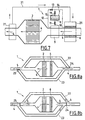
- the exhaust line 1, part of which is represented on the figure 1 is equipped with such a FAP 2 having a plurality of channels 3 through which flow according to the arrows 4 the exhaust gases to be cleaned of their polluting solid particles and from the upstream part of the line 1 (right on the figure 1 ).
- CaO lime is a preferred example of such a first solid compound, since it can react with water vapor according to the reversible reaction CaO + H 2 O ⁇ Ca (OH) 2 + 63.6 kJ / mol.H 2 O
- valve 11 When it is desired that the installation can be quickly operational, the valve 11 is opened ( figure 3 , where the open valve 11 is shown in clear) and the water 8 is sent into the evaporator 9 (arrow 20). This transfer can be carried out by a pump or by simple gravity if the configuration of the invention allows it. Once the transfer is complete, the valve 11 is closed, and the water 8 present in the evaporator is brought to the temperature of the exhaust gas circulating around the evaporator 9.
- the transfer operation of the water 8 in the evaporator 9 takes place during a period of stopping the vehicle, when the temperatures of the condenser 7 and the evaporator 9 tend to equalize. To symbolize this situation on the figure 3 we did not draw arrows 4 symbolizing the circulation of the exhaust gases.
- This operation can be initiated by the driver, or automatically.
- the timing of this trigger can be determined systematically according to the number of kilometers traveled since the last regeneration date.
- This triggering can also be decided because it would have been determined, by means of appropriate sensors, an unusually high pressure drop of the exhaust gases between the upstream and the downstream of the FAP 2, indicating a clogging of the channels 3 the FAP 2.
- the heat released is communicated to the soot deposited in the channels 3, via the walls of the FAP 2, the various parameters of the installation being chosen so that the soot is brought to a temperature above their combustion temperature, so as to initiate this combustion. In particular, the water vapor pressure must be sufficient.
- the channels 3 of the FAP 2 are thus freed from sooting.
- This combustion can be detected, for example, by measuring the difference in temperature of the exhaust gas or the pressure difference on either side of the FAP 2.
- the installation is passed through the configuration of the figure 6 , where the valves 11, 13 are closed and the valve 19 is open.
- the condenser 7 can be cooled by an external circulation of fluid, but a simple cooling by the ambient air can be sufficient.
- the state of rest of the installation is constituted by the state represented on the figure 4 where the water 8 is at the liquid-vapor equilibrium in the evaporator 9.
- the entire regeneration of the FAP 2 between the beginning of the admission of the water vapor 8 in the CaO 6 lime and the return of all the water vapor 8 in the condenser 7 can last about 1 minute, even less.
- the installation according to the invention has the very significant advantage of limiting the external energy inputs or even of eliminating them, apart from that, quite negligible, necessary for the control of the valves 11, 13, 19 and the operation of the sensors for determining the favorable moments for the initiation of the different stages of the cycle.
- This is made possible by the fact that the chemical reactions involved are, in a way, "self-sustaining", the heat of the exothermic hydration reaction of CaO lime triggering the exothermic reaction of soot combustion, whose heat The reaction in turn triggers the endothermic dehydration reaction of the Ca (OH) 2 hydroxide.
- a post-fuel injection is no longer necessarily useful for the regeneration of FAP 2. It is even possible, if the various characteristics of the facility are well adapted, to completely do without the addition of ceria to fuel, if the heat released by the hydration of lime CaO 6 proves itself capable of providing a sufficient temperature level to initiate the combustion of soot. The installation is therefore particularly economical to use.
- the FAP 2 - reactor assembly As the FAP 2 - reactor assembly is placed in a housing 20 which is open only in front of the elements of the FAP 2 and the passages for the lines 16, 17, 18, the lime CaO 6 is not in the path of the exhaust gas and do not come in contact with them. It is therefore not poisoned by impurities present in the fuel (sulfur for example).
- the configuration of FAP 2 and its environment as an example on Figures 1 to 6 is advantageous, in that the FAP 2 is heated both internally and externally by CaO 6 lime during the reaction hydration, and conversely lime 6 in the hydrated state is in all respects relatively close to the heat source represented by the FAP 2 heated during the combustion of soot. For these reasons, the efficiency of heat transfer and the course of chemical reactions that result can be optimized. But it would remain in the spirit of the invention to have the lime CaO 6 only around the FAP 2 or only in the center of the FAP 2. Conversely, it can be provided that a plurality of "bars" of lime CaO 6 are arranged inside the FAP 2 instead of one as in the example shown. In general, placing the CaO 6 lime at multiple points in the FAP 2 makes it possible to minimize the temperature gradients inside the FAP 2, and therefore the mechanical stresses to which it is subjected.
- Another variant with respect to the configuration shown would be to move the evaporator 9 downstream of the FAP 2, or outside the exhaust line 1 and in contact with its outer wall. In this way, a possible disturbance of the gaseous flows inside the FAP 2 is avoided.
- Integrating the reactor containing lime CaO 6 FAP 2 itself and / or its immediate environment has the advantages that have been cited, but is not without drawbacks.
- the heat produced by the various chemical reactions is consumed partly to heat the walls of the FAP 2 and not to directly heat the soot or hydrated lime 6.
- part of this heat is driven by the circulating exhaust gas and is also not recovered by the soot or lime 6 hydrated.
- Obtaining satisfactory results can therefore lead to substantially increase the external dimensions of the exhaust line compared to the usual practice.
- the reactor containing the lime CaO 6 is placed outside and around the exhaust line 1, upstream of the FAP 2.
- the evaporator 9 is also placed outside and around the line D 9, between the reactor containing lime CaO 6 and FAP 2. Heat transfer between the exhaust gas and these two devices are thus carried out through the wall of the exhaust line 1.
- a heat pipe 21 or any other functionally equivalent device makes it possible to transmit the heat of the exhaust gas located downstream of the FAP 2 to the reactor containing the CaO 6 lime placed upstream of FAP 2.
- the water contained in the evaporator 9 is brought in vapor form into the lime CaO 6 through the lines 12, 14 (the valve 13 being the only one open), and the heat of reaction the exhaust gases at a temperature above the soot combustion temperature.
- the soot combustion warms the exhaust gases whose heat is recovered by the heat pipe 21, the fluid of which transfers this heat to hydrated lime 6 for the regeneration of CaO lime. This results in the sending of steam into the condenser 7 (the valve 19 being the only one open).
- the heat transfer fluid of the heat pipe 21 returns to the downstream part thereof.
- This variant requires for its implementation on an existing exhaust line that a sufficient free space in the environment of the FAP 2 to implement the reactor containing lime CaO 6, the evaporator 9, the condenser 7 and the heat pipe 21
- Another advantage is that the exhaust gases heated upstream of the FAP 2 come into direct contact with the soot without requiring prior heating of the FAP 2, and that the heating of the FAP 2 following the combustion of the soot is substantially homogeneous in all its volume, which induces fewer constraints in the FAP 2 material.
- the reactor containing lime CaO 6 is placed upstream of the FAP 2 in the path of the exhaust gas if it is not integrated in the FAP 2 himself.
- the reactor containing the hydrated lime 6 it would be preferable for the reactor containing the hydrated lime 6 to be regenerated to be placed downstream of the FAP 2, so that it can be directly regenerated by the exhaust gases heated by the combustion of the soot. This can be done by adding to the exhaust line a device allowing the reversal of the flow direction of the exhaust gases through the FAP 2 between the two stages of reaction and regeneration of CaO 6 lime.
- the installation can be achieved by means of the installation shown on the Figures 8a, 8b .
- a FAP 2 On the exhaust line 1 is inserted a FAP 2, and a reactor containing lime CaO 6, separated from the FAP 2, and can be traversed by the exhaust gas through perforations or porosity adequate.
- the reactor 6 is placed upstream of the FAP 2 on the normal course of the exhaust gas.
- the installation also comprises an evaporator, a condenser and the pipes and valves necessary for the operation of the reactor, similar to those described for the preceding variants of the invention and which are not represented on the Figures 8a, 8b .
- the line 1 also comprises two bypass lines 22, 23 allowing the gases not to pass directly through the reactor 6 and the FAP 2 and two valves 24, 25 controlling the orientation of the exhaust gases to either the reactor 6 and the FAP 2 directly, either in bypass lines 22, 23.
- valves 24, 25 are in such positions that they isolate the bypass lines 22, 23 of the normal path of the exhaust gas. These then pass successively the reactor containing lime CaO 6 and FAP 2 (see figure 8a ).
- the valves 24, 25 are maintained in the previous position, and the water vapor is sent into the lime CaO 6 from the evaporator (not shown), from in order to cause the hydration reaction of the CaO 6 lime causing the exhaust gases to warm up before they pass through the FAP 2, and to start the soot combustion of the FAP 2.
- valves 24, 25 are actuated so that the exhaust gases first pass through the first bypass line 22, then pass through the FAP 2 where they are reheated by the combustion of the soot, then the reactor containing lime 6 in the hydrated state, so as to dehydrate, then the second bypass line 23, so as to be finally returned to the downstream part of the exhaust line 1.
- valves 24, 25 are returned to their initial positions and the exhaust line 1 starts to operate under normal conditions.
- the invention is not limited to the examples which have been described and shown. In particular, it would be possible to combine various alternatives, in particular to place reactors containing CaO 6 lime both inside and outside the FAP 2, and generally inside and outside the cell. outside the exhaust line 1.
- Another variant of the invention would be to place the reactor 6 containing the first solid compound inside or outside the exhaust line 1 downstream of the FAP 2, and to transmit the heat released by the combination of the first solid compound and the second gaseous compound to soot particles via a heat pipe directly FAP 2 and / or exhaust gases upstream of the FAP 2.
- the invention finds a preferred application to the exhaust lines of diesel engines, but it can be applied to the exhaust line of any type of internal combustion engine for which it would be necessary to use a particulate filter.
Landscapes
- Chemical & Material Sciences (AREA)
- Engineering & Computer Science (AREA)
- Chemical Kinetics & Catalysis (AREA)
- Combustion & Propulsion (AREA)
- Mechanical Engineering (AREA)
- General Engineering & Computer Science (AREA)
- Physics & Mathematics (AREA)
- Geometry (AREA)
- Filtering Of Dispersed Particles In Gases (AREA)
- Treating Waste Gases (AREA)
- Exhaust Gas After Treatment (AREA)
- Filtering Materials (AREA)
- Processes For Solid Components From Exhaust (AREA)
Claims (15)
- Verfahren zur Regenerierung eines Partikelfilters für die Abgasstrecke eines Verbrennungsmotors, bei dem man die die Wände des Filters bedeckenden Partikel so erhitzt, dass sie auf eine Temperatur gebracht werden, die höher als ihre Verbrennungstemperatur ist, dadurch gekennzeichnet, dass:- man die für die Erhitzung der Partikel erforderliche Wärme erzeugt, indem man einer in einem Reaktor vorliegenden, ersten festen Verbindung eine zweite Verbindung in Gasform zusetzt, die sich mit der ersten Verbindung kombiniert, um in einer ersten exothermen Reaktion eine dritte feste Verbindung zu bilden;- und man die durch die Verbrennung dieser Teilchen entstehende Wärme dazu verwendet, die in einem Reaktor vorliegende, erste feste Verbindung und die zweite Verbindung in Gasform in einer zweiten, zur ersten exothermen Reaktion umgekehrten, endothermen Reaktion zu regenerieren.
- Verfahren nach Anspruch 1, dadurch gekennzeichnet, dass man auf die Partikel die für ihre Erhitzung erforderliche Wärme und auf die dritte feste Verbindung die für die Regenerierung der ersten festen Verbindung erforderliche Wärme über die Wände des Partikelfilters überträgt.
- Verfahren nach Anspruch 1 oder 2, dadurch gekennzeichnet, dass man auf die Partikel die für ihre Erhitzung erforderliche Wärme und auf die dritte feste Verbindung die für die Regenerierung der ersten festen Verbindung erforderliche Wärme über die die Abgasstrecke durchströmenden Abgase überträgt.
- Verfahren nach einem der Ansprüche 1 bis 3, dadurch gekennzeichnet, dass die erste feste Verbindung Kalk CaO ist und dass die zweite Verbindung Wasser ist.
- Abgasstrecke (1) eines Verbrennungsmotors, umfassend ein Partikefilter (2) und Mittel zu seiner Regenerierung, die es gestatten, die die Wände des Filters (2) bedeckenden Partikel auf eine Temperatur zu bringen, die höher als ihre Verbrennungstemperatur ist, dadurch gekennzeichnet, dass diese Mittel umfassen:- mindestens einen Reaktor (6), der eine erste feste Verbindung enthält;- einen Verdampfer (9), der die Verdampfung einer zweiten Verbindung (8) gestattet, die sich mit der ersten festen Verbindung kombinieren kann, um in einer exothermen Reaktion eine dritte feste Verbindung zu bilden;- Mittel (12, 13, 14, 16, 17) zum Verbinden des Verdampfers (9) und des Reaktors (6) durch Steuerung;- Mittel zur Übertragung der durch die Kombination der ersten und der zweiten Verbindung freigesetzten Wärme auf die Partikel;- Mittel zur Übertragung der durch die Verbrennung der Teilchen freigesetzten Wärme auf die dritte feste Verbindung, so dass eine Regenerierung der ersten und der zweiten Verbindung während dieser Verbrennung bewirkt wird;- Mittel (15, 19) zur Aufnahme der zweiten Verbindung in Gasform bei der Regenerierung der ersten und der zweiten Verbindung und zu ihrer Übertragung in einen Kondensator (7), der ihre Verflüssigung gestattet;- und Mittel (10, 11) zum Verbinden des Kondensators und des Verdampfers durch Steuerung.
- Abgasstrecke (1) nach Anspruch 5, dadurch gekennzeichnet, dass in das Partikelfilter (2) mindestens ein die erste feste Verbindung enthaltender Reaktor (6) integriert ist.
- Abgasstrecke (1) nach Anspruch 5 oder 6, dadurch gekennzeichnet, dass mindestens ein die erste feste Verbindung enthaltender Reaktor (6) an die Außenwand de Abgasstrecke (1) angesetzt ist.
- Abgasstrecke (1) nach Anspruch 7, dadurch gekennzeichnet, dass die Mittel zur Übertragung der durch die Verbrennung der Partikel freigesetzten Reaktionswärme auf die dritte feste Verbindung eine Wärmeleitung (21) umfassen, die die stromab des Partikelfilters (2) von den Abgasen abgegebene Wärme sammelt.
- Abgasstrecke (1) nach Anspruch 5, dadurch gekennzeichnet, dass der die erste feste Verbindung enthaltende Reaktor (6) innerhalb oder außerhalb der Abgasstrecke (1) stromauf des Partikelfilters (2) in dem normalen Weg der Abgase angeordnet ist und dass die Mittel zur Übertragung der durch die Verbrennung der Partikel freigesetzten Reaktionswärme auf die dritte feste Verbindung Umgehungsleitungen (22, 23) und Ventile (24, 25) umfassen, die eine Änderung des Wegs der Abgase gestatten, so dass der Reaktor bei der Regenerierung der ersten und der zweiten Verbindung in dem Weg der Abgase stromab des Partikelfilters (2) angeordnet wird.
- Abgasstrecke (1) nach Anspruch 5, dadurch gekennzeichnet, dass der die erste feste Verbindung enthaltende Reaktor (6) innerhalb oder außerhalb der Abgasstrecke (1) stromab des Partikelfilters (2) angeordnet ist und dass sie eine Wärmeleitung umfasst, die die durch die Kombinierung der ersten und der zweiten Verbindung freigesetzte Wärme auf das Partikelfilter (2) und/oder auf die Abgase stromauf des Partikelfilters überträgt.
- Abgasstrecke (1) nach einem der Ansprüche 5 bis 10, dadurch gekennzeichnet, dass sie Mittel zum Erfassen einer Verstopfung des Partikelfilters (2) und zum Auslösen eines Prozesses der Regenerierung des Partikelfilters (2) umfasst.
- Abgasstrecke (1) nach einem der Ansprüche 5 bis 11, dadurch gekennzeichnet, sie Mittel zum Erfassen der Initiierung der Reaktion der Verbrennung der das Filter bedeckenden Partikel und zum Auslösen der Verbindung des Reaktors (6) und des Kondensators (7) umfasst.
- Partikelfilter (2) für die Abgasstrecke (1) eines Verbrennungsmotors, dadurch gekennzeichnet, dass es mindestens einen in einem Abstand von dem Weg der Abgase angeordneten Reaktor (6) umfasst, der eine erste feste Verbindung enthält, die mit einer zweiten Verbindung in einer reversiblen exothermen Reaktion so reagieren kann, dass die Wände des Filters (2) auf eine Temperatur gebracht werden, die höher als die Verbrennungstemperatur der Partikel ist, die von dem Filter (2) eingefangen werden sollen, wobei dieser Reaktor nur gegenüber dem Durchgang mindestens einer Leitung (14, 16, 17, 18) offen ist, die die Zufuhr der zweiten Verbindung in den Reaktor (6) und ihre Abfuhr aus diesem gestattet.
- Partikelfilter nach Anspruch 13, dadurch gekennzeichnet, dass ein Reaktor (6) um das Filter herum angeordnet ist.
- Partikelfilter nach Anspruch 13 oder 14, dadurch gekennzeichnet, dass mindestens ein Reaktor (6) in das Filter integriert ist.
Applications Claiming Priority (3)
| Application Number | Priority Date | Filing Date | Title |
|---|---|---|---|
| FR0213548 | 2002-10-29 | ||
| FR0213548A FR2846367B1 (fr) | 2002-10-29 | 2002-10-29 | Procede et dispositif de regeneration d'un filtre a particules pour ligne d'echappement, et filtre a particules adapte |
| PCT/FR2003/003210 WO2004040102A1 (fr) | 2002-10-29 | 2003-10-28 | Procede et dispositif de regeneration d'un filtre a particules pour ligne d' echappement, et filtre a particules adapte |
Publications (2)
| Publication Number | Publication Date |
|---|---|
| EP1556586A1 EP1556586A1 (de) | 2005-07-27 |
| EP1556586B1 true EP1556586B1 (de) | 2008-07-30 |
Family
ID=32088399
Family Applications (1)
| Application Number | Title | Priority Date | Filing Date |
|---|---|---|---|
| EP03780238A Expired - Lifetime EP1556586B1 (de) | 2002-10-29 | 2003-10-28 | Verfahren und vorrichtung zur regenerierung eines partikelfilters für abgasleitungen, und geeigneter partikelfilter |
Country Status (7)
| Country | Link |
|---|---|
| US (1) | US20060153753A1 (de) |
| EP (1) | EP1556586B1 (de) |
| AT (1) | ATE403072T1 (de) |
| AU (1) | AU2003288334A1 (de) |
| DE (1) | DE60322566D1 (de) |
| FR (1) | FR2846367B1 (de) |
| WO (1) | WO2004040102A1 (de) |
Families Citing this family (5)
| Publication number | Priority date | Publication date | Assignee | Title |
|---|---|---|---|---|
| DE102006032886A1 (de) * | 2006-07-15 | 2008-01-17 | Daimler Ag | Partikelabscheider und Verfahren zur Regeneration eines Partikelabscheiders |
| FR2913454B1 (fr) * | 2007-03-06 | 2009-06-05 | Peugeot Citroen Automobiles Sa | Dispositif de rechauffage des gaz d'echappement d'un moteur, collecteur d'echappement et ligne d'echappement adaptes, et vehicule les comportant. |
| JP2009115064A (ja) * | 2007-11-09 | 2009-05-28 | Toyota Industries Corp | 排ガス浄化装置 |
| US8091337B2 (en) * | 2008-02-29 | 2012-01-10 | Corning Incorporated | Exhaust treatment device having a reactive compound and conditioning the device via endothermic reaction |
| CN114543058B (zh) * | 2022-02-25 | 2023-07-21 | 中国科学院电工研究所 | 一种基于太阳能的高温蒸汽发生器 |
Family Cites Families (6)
| Publication number | Priority date | Publication date | Assignee | Title |
|---|---|---|---|---|
| EP0160482B1 (de) * | 1984-04-23 | 1989-01-11 | Engelhard Corporation | Katalytischer Abgasfilter für Teilchen eines Dieselmotors |
| JPH05141228A (ja) * | 1991-03-20 | 1993-06-08 | Hitachi Ltd | 内燃機関の排気ガス浄化方法 |
| JPH07180539A (ja) * | 1993-12-24 | 1995-07-18 | Mitsubishi Electric Corp | 化学発熱装置 |
| US5707593A (en) * | 1996-12-31 | 1998-01-13 | Wang Chi | Energy self-sustainable reactor for gasifying engine particulates and unburned hydrocarbons |
| WO2002026379A1 (en) * | 2000-09-29 | 2002-04-04 | Omg Ag & Co. Kg | Catalytic soot filter and use thereof in treatment of lean exhaust gases |
| US20020139113A1 (en) * | 2001-04-03 | 2002-10-03 | Guillermo Almagro | Diesel soot burning device |
-
2002
- 2002-10-29 FR FR0213548A patent/FR2846367B1/fr not_active Expired - Fee Related
-
2003
- 2003-10-28 WO PCT/FR2003/003210 patent/WO2004040102A1/fr not_active Ceased
- 2003-10-28 AU AU2003288334A patent/AU2003288334A1/en not_active Abandoned
- 2003-10-28 AT AT03780238T patent/ATE403072T1/de not_active IP Right Cessation
- 2003-10-28 EP EP03780238A patent/EP1556586B1/de not_active Expired - Lifetime
- 2003-10-28 US US10/533,105 patent/US20060153753A1/en not_active Abandoned
- 2003-10-28 DE DE60322566T patent/DE60322566D1/de not_active Expired - Fee Related
Also Published As
| Publication number | Publication date |
|---|---|
| ATE403072T1 (de) | 2008-08-15 |
| DE60322566D1 (de) | 2008-09-11 |
| WO2004040102A1 (fr) | 2004-05-13 |
| US20060153753A1 (en) | 2006-07-13 |
| AU2003288334A1 (en) | 2004-05-25 |
| FR2846367B1 (fr) | 2006-08-04 |
| FR2846367A1 (fr) | 2004-04-30 |
| EP1556586A1 (de) | 2005-07-27 |
| AU2003288334A8 (en) | 2004-05-25 |
Similar Documents
| Publication | Publication Date | Title |
|---|---|---|
| FR2642012A1 (fr) | Dispositif pour le chauffage de vehicules automobiles equipes d'un moteur a combustion interne, notamment d'autobus | |
| CA2658216A1 (fr) | Bruleur et procede pour la regeneration de cartouches de filtration et dispositifs equipes d'un tel bruleur | |
| EP2147198B1 (de) | Verfahren und vorrichtung zur entfrostung eines abgasbearbeitungszusatzes | |
| EP1556586B1 (de) | Verfahren und vorrichtung zur regenerierung eines partikelfilters für abgasleitungen, und geeigneter partikelfilter | |
| FR2721095A1 (fr) | Four de traitement thermique de déchets et procédé associé. | |
| FR2820341A1 (fr) | Dispositif de traitement des gaz d'echappement d'un moteur a combustion interne comportant un catalyseur accumulateur | |
| WO2013114046A1 (fr) | Dispositif de chauffage d'un moteur thermique d'un vehicule | |
| FR2809766A1 (fr) | Procede de regeneration d'un filtre a particules et installation de regeneration d'un filtre a particules | |
| EP1672194B1 (de) | Verfahren zur Regeneration eines Partikelfilters mit einer katalytischen Verbrennungseinheit und das Verfahren verwendende Filtervorrichtung | |
| EP1553272B1 (de) | Verfahren und Vorrichtung zur Kontrolle der Temperatur eines NOx-Speichers im Abgasstrang einer Brennkraftmaschine | |
| FR3066408B1 (fr) | Dispositif de post-traitement des gaz d’echappement d’un moteur thermique | |
| EP1967713A1 (de) | Vorrichtung zur Erwärmung von Abgasen eines Motors, entsprechend angepasster Auspuffkrümmer und entsprechend angepasstes Auspuffrohr sowie mit einer solchen Vorrichtung ausgestattetes Fahrzeug | |
| FR3107729A1 (fr) | Ligne d’échappement | |
| FR2813096A1 (fr) | Dispositif et procede de traitement des gaz d'echappement d'un moteur a combustion interne | |
| FR3002000A1 (fr) | Ensemble comportant un ecran thermique permettant le chauffage d'un reservoir de reducteur | |
| EP1461515B1 (de) | Verfahren zum kühlen von teilchenfiltern durch einspritzen von ammoniumnitrtat und vorrichtung dafür | |
| EP1417997A1 (de) | Katalitische Reinigungsverfahren für einen Motor eines Kraftzeugs und zugehöriges Verfahren zur Wasserstofferzeugung | |
| FR2698909A1 (fr) | Dispositif d'échappement pour moteur à combustion interne. | |
| FR2995942A1 (fr) | Systeme et procede pour reduire la quantite d'oxydes d'azote dans les gaz d'echappement d'un vehicule automobile | |
| CA2671884A1 (fr) | Media filtrant pour dispositif de filtration des gaz d'echappement d'un moteur diesel, dispositif de filtration mettant en oeuvre un tel media, et ligne d'echappement des gaz d'unmoteur a combustion interne mettant en oeuvre un tel dispositif | |
| FR3159656A1 (fr) | Installation de moteur à combustion interne à hydrogène | |
| FR2846256A1 (fr) | Procede d'utilisation d'un transformateur thermochimique, et dispositif comportant un reacteur chimique et un transformateur thermochimique | |
| FR2921971A1 (fr) | Ligne d'echappement de moteur de vehicule automobile comportant un dispositif empechant un echauffement critique | |
| FR2978205A1 (fr) | Procede de suppression de cristaux d'uree dans la ligne d'echappement d'un moteur a combustion interne | |
| FR2821116A1 (fr) | Procede et dispositif de regeneration d'un filtre a particules d'un moteur thermique |
Legal Events
| Date | Code | Title | Description |
|---|---|---|---|
| PUAI | Public reference made under article 153(3) epc to a published international application that has entered the european phase |
Free format text: ORIGINAL CODE: 0009012 |
|
| 17P | Request for examination filed |
Effective date: 20050419 |
|
| AK | Designated contracting states |
Kind code of ref document: A1 Designated state(s): AT BE BG CH CY CZ DE DK EE ES FI FR GB GR HU IE IT LI LU MC NL PT RO SE SI SK TR |
|
| AX | Request for extension of the european patent |
Extension state: AL LT LV MK |
|
| RIN1 | Information on inventor provided before grant (corrected) |
Inventor name: BOUDARD, EMMANUEL Inventor name: MAURAN, SYLVAIN Inventor name: STITOU, DRISS Inventor name: GUIGUET, SANDRINE |
|
| DAX | Request for extension of the european patent (deleted) | ||
| GRAP | Despatch of communication of intention to grant a patent |
Free format text: ORIGINAL CODE: EPIDOSNIGR1 |
|
| GRAS | Grant fee paid |
Free format text: ORIGINAL CODE: EPIDOSNIGR3 |
|
| GRAA | (expected) grant |
Free format text: ORIGINAL CODE: 0009210 |
|
| AK | Designated contracting states |
Kind code of ref document: B1 Designated state(s): AT BE BG CH CY CZ DE DK EE ES FI FR GB GR HU IE IT LI LU MC NL PT RO SE SI SK TR |
|
| REG | Reference to a national code |
Ref country code: GB Ref legal event code: FG4D Free format text: NOT ENGLISH |
|
| REG | Reference to a national code |
Ref country code: CH Ref legal event code: EP |
|
| REF | Corresponds to: |
Ref document number: 60322566 Country of ref document: DE Date of ref document: 20080911 Kind code of ref document: P |
|
| REG | Reference to a national code |
Ref country code: IE Ref legal event code: FG4D Free format text: LANGUAGE OF EP DOCUMENT: FRENCH |
|
| PGFP | Annual fee paid to national office [announced via postgrant information from national office to epo] |
Ref country code: GB Payment date: 20080926 Year of fee payment: 6 |
|
| PG25 | Lapsed in a contracting state [announced via postgrant information from national office to epo] |
Ref country code: NL Free format text: LAPSE BECAUSE OF FAILURE TO SUBMIT A TRANSLATION OF THE DESCRIPTION OR TO PAY THE FEE WITHIN THE PRESCRIBED TIME-LIMIT Effective date: 20080730 Ref country code: ES Free format text: LAPSE BECAUSE OF FAILURE TO SUBMIT A TRANSLATION OF THE DESCRIPTION OR TO PAY THE FEE WITHIN THE PRESCRIBED TIME-LIMIT Effective date: 20081110 Ref country code: PT Free format text: LAPSE BECAUSE OF FAILURE TO SUBMIT A TRANSLATION OF THE DESCRIPTION OR TO PAY THE FEE WITHIN THE PRESCRIBED TIME-LIMIT Effective date: 20081230 |
|
| PGFP | Annual fee paid to national office [announced via postgrant information from national office to epo] |
Ref country code: DE Payment date: 20081030 Year of fee payment: 6 |
|
| PG25 | Lapsed in a contracting state [announced via postgrant information from national office to epo] |
Ref country code: AT Free format text: LAPSE BECAUSE OF FAILURE TO SUBMIT A TRANSLATION OF THE DESCRIPTION OR TO PAY THE FEE WITHIN THE PRESCRIBED TIME-LIMIT Effective date: 20080730 Ref country code: BG Free format text: LAPSE BECAUSE OF FAILURE TO SUBMIT A TRANSLATION OF THE DESCRIPTION OR TO PAY THE FEE WITHIN THE PRESCRIBED TIME-LIMIT Effective date: 20081030 Ref country code: FI Free format text: LAPSE BECAUSE OF FAILURE TO SUBMIT A TRANSLATION OF THE DESCRIPTION OR TO PAY THE FEE WITHIN THE PRESCRIBED TIME-LIMIT Effective date: 20080730 Ref country code: SI Free format text: LAPSE BECAUSE OF FAILURE TO SUBMIT A TRANSLATION OF THE DESCRIPTION OR TO PAY THE FEE WITHIN THE PRESCRIBED TIME-LIMIT Effective date: 20080730 |
|
| REG | Reference to a national code |
Ref country code: IE Ref legal event code: FD4D |
|
| BERE | Be: lapsed |
Owner name: CENTRE NATIONAL DE LA RECHERCHE SCIENTIFIQUE (CNR Effective date: 20081031 Owner name: PEUGEOT CITROEN AUTOMOBILES SA Effective date: 20081031 |
|
| PG25 | Lapsed in a contracting state [announced via postgrant information from national office to epo] |
Ref country code: DK Free format text: LAPSE BECAUSE OF FAILURE TO SUBMIT A TRANSLATION OF THE DESCRIPTION OR TO PAY THE FEE WITHIN THE PRESCRIBED TIME-LIMIT Effective date: 20080730 Ref country code: IE Free format text: LAPSE BECAUSE OF FAILURE TO SUBMIT A TRANSLATION OF THE DESCRIPTION OR TO PAY THE FEE WITHIN THE PRESCRIBED TIME-LIMIT Effective date: 20080730 Ref country code: EE Free format text: LAPSE BECAUSE OF FAILURE TO SUBMIT A TRANSLATION OF THE DESCRIPTION OR TO PAY THE FEE WITHIN THE PRESCRIBED TIME-LIMIT Effective date: 20080730 |
|
| PGFP | Annual fee paid to national office [announced via postgrant information from national office to epo] |
Ref country code: FR Payment date: 20081028 Year of fee payment: 6 |
|
| PG25 | Lapsed in a contracting state [announced via postgrant information from national office to epo] |
Ref country code: SK Free format text: LAPSE BECAUSE OF FAILURE TO SUBMIT A TRANSLATION OF THE DESCRIPTION OR TO PAY THE FEE WITHIN THE PRESCRIBED TIME-LIMIT Effective date: 20080730 Ref country code: CZ Free format text: LAPSE BECAUSE OF FAILURE TO SUBMIT A TRANSLATION OF THE DESCRIPTION OR TO PAY THE FEE WITHIN THE PRESCRIBED TIME-LIMIT Effective date: 20080730 Ref country code: RO Free format text: LAPSE BECAUSE OF FAILURE TO SUBMIT A TRANSLATION OF THE DESCRIPTION OR TO PAY THE FEE WITHIN THE PRESCRIBED TIME-LIMIT Effective date: 20080730 Ref country code: MC Free format text: LAPSE BECAUSE OF NON-PAYMENT OF DUE FEES Effective date: 20081031 |
|
| REG | Reference to a national code |
Ref country code: CH Ref legal event code: PL |
|
| PLBE | No opposition filed within time limit |
Free format text: ORIGINAL CODE: 0009261 |
|
| STAA | Information on the status of an ep patent application or granted ep patent |
Free format text: STATUS: NO OPPOSITION FILED WITHIN TIME LIMIT |
|
| 26N | No opposition filed |
Effective date: 20090506 |
|
| PG25 | Lapsed in a contracting state [announced via postgrant information from national office to epo] |
Ref country code: IT Free format text: LAPSE BECAUSE OF FAILURE TO SUBMIT A TRANSLATION OF THE DESCRIPTION OR TO PAY THE FEE WITHIN THE PRESCRIBED TIME-LIMIT Effective date: 20080730 |
|
| PG25 | Lapsed in a contracting state [announced via postgrant information from national office to epo] |
Ref country code: BE Free format text: LAPSE BECAUSE OF NON-PAYMENT OF DUE FEES Effective date: 20081031 |
|
| PG25 | Lapsed in a contracting state [announced via postgrant information from national office to epo] |
Ref country code: LI Free format text: LAPSE BECAUSE OF NON-PAYMENT OF DUE FEES Effective date: 20081031 Ref country code: CH Free format text: LAPSE BECAUSE OF NON-PAYMENT OF DUE FEES Effective date: 20081031 |
|
| PG25 | Lapsed in a contracting state [announced via postgrant information from national office to epo] |
Ref country code: SE Free format text: LAPSE BECAUSE OF FAILURE TO SUBMIT A TRANSLATION OF THE DESCRIPTION OR TO PAY THE FEE WITHIN THE PRESCRIBED TIME-LIMIT Effective date: 20081030 |
|
| REG | Reference to a national code |
Ref country code: FR Ref legal event code: ST Effective date: 20100630 |
|
| PG25 | Lapsed in a contracting state [announced via postgrant information from national office to epo] |
Ref country code: FR Free format text: LAPSE BECAUSE OF NON-PAYMENT OF DUE FEES Effective date: 20091102 Ref country code: HU Free format text: LAPSE BECAUSE OF FAILURE TO SUBMIT A TRANSLATION OF THE DESCRIPTION OR TO PAY THE FEE WITHIN THE PRESCRIBED TIME-LIMIT Effective date: 20090131 Ref country code: CY Free format text: LAPSE BECAUSE OF FAILURE TO SUBMIT A TRANSLATION OF THE DESCRIPTION OR TO PAY THE FEE WITHIN THE PRESCRIBED TIME-LIMIT Effective date: 20080730 Ref country code: LU Free format text: LAPSE BECAUSE OF NON-PAYMENT OF DUE FEES Effective date: 20081028 Ref country code: DE Free format text: LAPSE BECAUSE OF NON-PAYMENT OF DUE FEES Effective date: 20100501 |
|
| PG25 | Lapsed in a contracting state [announced via postgrant information from national office to epo] |
Ref country code: TR Free format text: LAPSE BECAUSE OF FAILURE TO SUBMIT A TRANSLATION OF THE DESCRIPTION OR TO PAY THE FEE WITHIN THE PRESCRIBED TIME-LIMIT Effective date: 20080730 |
|
| PG25 | Lapsed in a contracting state [announced via postgrant information from national office to epo] |
Ref country code: GR Free format text: LAPSE BECAUSE OF FAILURE TO SUBMIT A TRANSLATION OF THE DESCRIPTION OR TO PAY THE FEE WITHIN THE PRESCRIBED TIME-LIMIT Effective date: 20081031 |
|
| PG25 | Lapsed in a contracting state [announced via postgrant information from national office to epo] |
Ref country code: GB Free format text: LAPSE BECAUSE OF NON-PAYMENT OF DUE FEES Effective date: 20091028 |