EP1556616B1 - Laufrad für eine kreiselpumpe - Google Patents
Laufrad für eine kreiselpumpe Download PDFInfo
- Publication number
- EP1556616B1 EP1556616B1 EP03773454A EP03773454A EP1556616B1 EP 1556616 B1 EP1556616 B1 EP 1556616B1 EP 03773454 A EP03773454 A EP 03773454A EP 03773454 A EP03773454 A EP 03773454A EP 1556616 B1 EP1556616 B1 EP 1556616B1
- Authority
- EP
- European Patent Office
- Prior art keywords
- centrifugal pump
- impeller
- rotor according
- blades
- suction
- Prior art date
- Legal status (The legal status is an assumption and is not a legal conclusion. Google has not performed a legal analysis and makes no representation as to the accuracy of the status listed.)
- Expired - Lifetime
Links
Images
Classifications
-
- F—MECHANICAL ENGINEERING; LIGHTING; HEATING; WEAPONS; BLASTING
- F04—POSITIVE - DISPLACEMENT MACHINES FOR LIQUIDS; PUMPS FOR LIQUIDS OR ELASTIC FLUIDS
- F04D—NON-POSITIVE-DISPLACEMENT PUMPS
- F04D29/00—Details, component parts, or accessories
- F04D29/18—Rotors
- F04D29/22—Rotors specially for centrifugal pumps
- F04D29/24—Vanes
- F04D29/242—Geometry, shape
-
- F—MECHANICAL ENGINEERING; LIGHTING; HEATING; WEAPONS; BLASTING
- F04—POSITIVE - DISPLACEMENT MACHINES FOR LIQUIDS; PUMPS FOR LIQUIDS OR ELASTIC FLUIDS
- F04D—NON-POSITIVE-DISPLACEMENT PUMPS
- F04D29/00—Details, component parts, or accessories
- F04D29/18—Rotors
- F04D29/22—Rotors specially for centrifugal pumps
- F04D29/2205—Conventional flow pattern
- F04D29/2216—Shape, geometry
Definitions
- the invention relates to an impeller for a centrifugal pump and to a use of the impeller.
- Impellers for centrifugal pumps are known. They are provided with blades through which the medium to be conveyed, which is introduced perpendicular to the blades, deflected in the radial direction and is discharged laterally from the impeller to the discharge nozzle of the centrifugal pump.
- the structural design of blades is particularly important.
- “Turbomachines” by Karl Pfleiderer, Hartwig Petermann, 6th edition pages 156 to 165 aspects are outlined, according to which the blades are constructive design. In this case, it is found, for example, that the course of the suction edge of the blade is to be selected so that it adjoins the side walls at as far as possible with steep angles, at a sufficient distance from the pressure edge.
- US-A-3,444,817 discloses curved blade suction edges, while in US-A-5,730,582 design criteria for suction edges of the blades are shown.
- the invention has for its object to provide an impeller for a centrifugal pump, in which a relatively high efficiency can be achieved even in smaller structural versions.
- the object underlying the invention is achieved by an impeller for a centrifugal pump in which at least three blades are arranged between a front cover disk and a rear cover disk, wherein the arc of the suction edge of at least one blade in the plan view of the inlet side of the medium to be conveyed sinusoidal With a single point of inflection W runs.
- the suction edge is to be understood as meaning the edge of each blade facing the flowing medium.
- promotional media can liquids, gases or suspensions, for example be used.
- the point of inflection is the point of the arc that separates two parts of different curvature.
- the arcuate course is meant, which offers the observer in the plan view of the inlet side of the medium to be conveyed.
- the impeller has a relatively high efficiency even with smaller structural configurations. This is for example given when the diameter of the impeller is between 5 and 6 cm.
- the efficiency is to be understood, for example, as the quotient of the discharged hydraulic power and the supplied power, the product of throughput and pressure difference being meant by the discharged hydraulic power. In most cases, both an increase in throughput and an increase in the pressure difference can be achieved.
- a preferred embodiment of the invention is that the inflection point W is closer to the inner end B of the arc of the suction edge than at the outer end A of the arc of the suction edge. By this measure, the efficiency can be further increased.
- the impeller for a centrifugal pump is characterized in a particularly advantageous manner suitable for many uses.
- the arches of the suction edges of all blades are formed identically.
- the arcs of the suction edges of all blades in the plan view of the inlet side of the medium to be conveyed sinusoidal with a single point of inflection W extend.
- all inner ends B of the sheets of the suction edges lie on a circle relative to the plan view of the inlet side of the medium to be conveyed. This optimizes the flow behavior inside the impeller for the centrifugal pump.
- the flow direction of the medium to be conveyed facing side of the rear cover plate is convex.
- an otherwise common intake spinner in the form of a bead-like projection is omitted.
- the convex formation improves the flow properties in the area of the rear cover disk.
- the direction of flow of the medium to be conveyed side facing the rear cover plate centered on a flat surface.
- a storage space is created on the flat surface, in which there is turbulence, through which the flowing medium can laterally reach the exit of the impeller in a preferred manner.
- the invention is finally the use of the impeller in a centrifugal pump for the promotion of cooling water in a motor vehicle.
- the cooling in the motor vehicle can be optimized, which is a direct result of the increase in the efficiency of the impeller for a centrifugal pump.
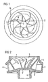
- Fig. 1 shows the impeller for a centrifugal pump in plan view.
- Fig. 2 shows the impeller for a centrifugal pump in cross section.
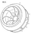
- Fig. 3 shows the impeller for a centrifugal pump in the three-dimensional representation.
- the impeller for a centrifugal pump is shown in plan view.
- the impeller has a plurality of blades 1, wherein the arc 2 of the suction edge of the blades 1 sinusoidally extends with a single inflection point W.
- the sinusoidal course is illustrated by the coordinate system with the abscissa X and the ordinate Y.
- the associated sheet 2 of the suction edge is highlighted in bold.
- the point of inflection W is closer to the inner end B of the sheet 2 of the suction edge as the outer end A of the sheet 2 of the suction edge.
- seven blades 1 are arranged.
- the sheets 2 of the suction edges of all blades 1 are formed similar. All inner ends B of the sheets 2 of the suction edges are, based on the plan view of the inlet side of the medium to be conveyed, on a circle. 7
- the impeller for a centrifugal pump is shown in cross section. It has in the middle an inlet side 3 for the medium to be conveyed.
- the medium to be pumped flows through the impeller for the centrifugal pump and passes through the outlet 4 of the impeller to the discharge nozzle of the centrifugal pump (not shown).
- the direction of flow of the medium to be conveyed facing side 6 'of the rear cover plate 6 is convex and has centrally a flat surface 6 "on this flat surface 6" forms during operation a storage space for the medium to be conveyed, thereby faster can get to the exit side 4 of the impeller.
- the individual blades 1 are arranged between the front cover disk 5 and the rear cover disk 6.
- the impeller for a centrifugal pump is shown in three dimensions. It is usually made of plastic. In this case, thermosets are used in a particularly advantageous manner. Particularly advantageously, the impeller is used in a centrifugal pump for the promotion of cooling water in a motor vehicle. The diameter of the impeller is then between 4 and 7 cm. Although such an impeller is designed to be relatively small, a relatively high efficiency of the centrifugal pump can be achieved.
Landscapes
- Engineering & Computer Science (AREA)
- Physics & Mathematics (AREA)
- Geometry (AREA)
- Mechanical Engineering (AREA)
- General Engineering & Computer Science (AREA)
- Structures Of Non-Positive Displacement Pumps (AREA)
Description
- Die Erfindung bezieht sich auf ein Laufrad für eine Kreiselpumpe sowie auf eine Verwendung des Laufrades.
- Laufräder für Kreiselpumpen sind bekannt. Sie sind mit Schaufeln versehen, durch welche das zu fördernde Medium, das senkrecht auf die Schaufeln eingeleitet wird, in radialer Richtung umgelenkt und seitlich aus dem Laufrad zum Druckstutzen der Kreiselpumpe abgeleitet wird. Der konstruktiven Ausgestaltung von Schaufeln kommt dabei eine besonders hohe Bedeutung zu. In "Strömungsmaschinen" von Karl Pfleiderer, Hartwig Petermann, 6. Auflage, Seiten 156 bis 165 werden Aspekte dargelegt, nach welchen die Schaufeln konstruktiv auszugestalten sind. Dabei wird beispielsweise herausgestellt, dass der Verlauf der Saugkante der Schaufel so gewählt werden soll, dass sie in genügendem Abstand von der Druckkante an die Seitenwände mit möglichst steilen Winkeln anschließt.
- Die US-A-3,444,817 offenbart gekrümmte Schaufelsaugkanten, während in der US-A-5,730,582 Auslegungskriterien für Saugkanten der Schaufeln aufgezeigt werden.
- Der Erfindung liegt die Aufgabe zugrunde, ein Laufrad für eine Kreiselpumpe zu schaffen, bei dem auch in kleineren baulichen Ausführungen ein relativ hoher Wirkungsgrad erreicht werden kann.
- Die der Erfindung zugrunde liegende Aufgabe wird durch ein Laufrad für eine Kreiselpumpe gelöst, bei dem zwischen einer vorderen Deckscheibe und einer hinteren Deckscheibe mindestens drei Schaufeln angeordnet sind, wobei der Bogen der Saugkante mindestens einer Schaufel in der Draufsicht auf die Eintrittsseite des zu fördernden Mediums sinusförmig mit einem einzigen Wendepunkt W verläuft. Als Saugkante ist dabei die dem strömenden Medium zugewandte Kante einer jeden Schaufel zu verstehen. Als fördernde Medien können Flüssigkeiten, Gase oder beispielsweise auch Suspensionen eingesetzt werden. Als Wendepunkt ist derjenige Punkt des Bogens zu verstehen, der zwei Teile verschiedener Krümmung trennt. Dabei ist der bogenförmige Verlauf gemeint, der sich dem Betrachter in der Draufsicht auf die Eintrittsseite des zu fördernden Mediums bietet. Es hat sich in überraschender Weise gezeigt, dass das Laufrad auch bei kleineren konstruktiven Ausgestaltungen einen relativ hohen Wirkungsgrad aufweist. Dies ist beispielsweise dann gegeben, wenn der Durchmesser des Laufrades zwischen 5 und 6 cm beträgt. Je größer das Laufrad für die Kreiselpumpe konstruktiv ausgelegt ist, desto höher ist der Wirkungsgrad. Dabei ist unter dem Wirkungsgrad beispielsweise der Quotient aus der abgeführten hydraulischen Leistung und der zugeführten Leistung zu verstehen, wobei mit der abgeführten hydraulischen Leistung das Produkt aus Durchsatz und Druckdifferenz gemeint ist. In den meisten Fällen lässt sich dadurch sowohl eine Erhöhung des Durchsatzes als auch eine Erhöhung der Druckdifferenz erzielen.
- Eine bevorzugte Ausgestaltung der Erfindung besteht darin, dass der Wendepunkt W näher am inneren Ende B des Bogens der Saugkante als am äußeren Ende A des Bogens der Saugkante liegt. Durch diese Maßnahme lässt sich der Wirkungsgrad noch weiter steigern.
- Gemäß einer weiteren bevorzugten Ausgestaltung der Erfindung werden 7 bis 15 Schaufeln angeordnet. Das Laufrad für eine Kreiselpumpe ist dadurch in besonders vorteilhafter Weise für vielerlei Einsatzzwecke geeignet.
- Nach einer weiteren bevorzugten Ausgestaltung der Erfindung ist vorgesehen, dass die Bögen der Saugkanten aller Schaufeln gleichartig ausgebildet sind. Unter der gleichartigen Ausbildung ist dabei zu verstehen, dass die Bögen der Saugkanten aller Schaufeln in der Draufsicht auf die Eintrittsseite des zu fördernden Mediums sinusförmig mit einem einzigen Wendepunkt W verlaufen. Durch diese Maßnahme wird der Wirkungsgrad ebenfalls erhöht und gleichzeitig die Fertigung des Laufrades erleichtert.
- Gemäß einer weiteren bevorzugten Ausgestaltung der Erfindung ist vorgesehen, dass alle inneren Enden B der Bögen der Saugkanten bezogen auf die Draufsicht auf die Eintrittsseite des zu fördernden Mediums auf einem Kreis liegen. Dies optimiert das Strömungsverhalten im Inneren des Laufrades für die Kreiselpumpe.
- Gemäß einer weiteren bevorzugten Ausgestaltung der Erfindung ist die der Strömungsrichtung des zu fördernden Mediums zugewandte Seite der hinteren Deckscheibe konvex ausgebildet. Auf die Anordnung eines sonst üblichen Einlaufspinners in Form eines wulstartigen Vorsprunges wird dabei verzichtet. Die konvexe Ausbildung verbessert die Strömungseigenschaften im Bereich der hinteren Deckscheibe.
- Gemäß einer weiteren Ausgestaltung der Erfindung weist die der Strömungsrichtung des zu fördernden Mediums zugewandten Seite der hinteren Deckscheibe mittig eine plane Fläche auf. Auf diese Weise wird an der planen Fläche ein Stauraum geschaffen, in dem es zur Verwirbelungen kommt, durch welche das strömende Medium seitlich in bevorzugter Weise zum Austritt des Laufrades gelangen kann.
- Gegenstand der Erfindung ist schließlich die Verwendung des Laufrades in einer Kreiselpumpe zur Förderung von Kühlwasser in einem Kraftfahrzeug. Auf diese Weise lässt sich die Kühlung im Kraftfahrzeug optimieren, was eine direkte Folge der Erhöhung des Wirkungsgrades durch das Laufrad für eine Kreiselpumpe ist.
- Die Erfindung wird nachfolgend anhand der Zeichnung (Fig. 1 bis Fig. 3) näher und beispielhaft erläutert.
- Fig. 1 zeigt das Laufrad für eine Kreiselpumpe in der Draufsicht.
- Fig. 2 zeigt das Laufrad für eine Kreiselpumpe im Querschnitt.
- Fig. 3 zeigt das Laufrad für eine Kreiselpumpe in der dreidimensionalen Darstellung.
- In Fig. 1 ist das Laufrad für eine Kreiselpumpe in der Draufsicht dargestellt. Das Laufrad weist mehrere Schaufeln 1 auf, wobei der Bogen 2 der Saugkante der Schaufeln 1 sinusförmig mit einem einzigen Wendepunkt W verläuft. Der sinusförmige Verlauf wird durch das Koordinatensystem mit der Abszisse X und der Ordinate Y verdeutlicht. Der zugehörige Bogen 2 der Saugkante ist dabei fettgedruckt herausgestellt. Der Wendepunkt W liegt dabei näher am inneren Ende B des Bogens 2 der Saugkante als am äußeren Ende A des Bogens 2 der Saugkante. Insgesamt sind sieben Schaufeln 1 angeordnet. Die Bögen 2 der Saugkanten aller Schaufeln 1 sind dabei gleichartig ausgebildet. Alle inneren Enden B der Bögen 2 der Saugkanten liegen, bezogen auf die Draufsicht auf die Eintrittsseite des zu fördernden Mediums, auf einem Kreis 7.
- In Fig. 2 ist das Laufrad für eine Kreiselpumpe im Querschnitt dargestellt. Es weist mittig eine Eintrittsseite 3 für das zu fördernde Medium auf. Das zu fördernde Medium durchströmt das Laufrad für die Kreiselpumpe und gelangt über den Austritt 4 des Laufrades zum Druckstutzen der Kreiselpumpe (nicht dargestellt). Die der Strömungsrichtung des zu fördernden Mediums zugewandte Seite 6' der hinteren Deckscheibe 6 ist konvex ausgebildet und weist mittig eine plane Fläche 6" auf. An dieser planen Fläche 6" bildet sich im Betrieb ein Stauraum für das zu fördernde Medium aus, das dadurch schneller zur Austrittsseite 4 des Laufrades gelangen kann. Die einzelnen Schaufeln 1 sind zwischen der vorderen Deckscheibe 5 und der hinteren Deckscheibe 6 angeordnet.
- In Fig. 3 ist das Laufrad für eine Kreiselpumpe dreidimensional dargestellt. Es wird in der Regel aus Kunststoff hergestellt. Dabei kommen in besonders vorteilhafter Weise Duroplaste zum Einsatz. Besonders vorteilhaft wird das Laufrad in einer Kreiselpumpe zur Förderung von Kühlwasser in einem Kraftfahrzeug eingesetzt. Der Durchmesser des Laufrades liegt dann zwischen 4 und 7 cm. Obwohl ein solches Laufrad relativ klein ausgestaltet ist, lässt sich ein relativ hoher Wirkungsgrad der Kreiselpumpe erreichen.
Claims (8)
- Laufrad für eine Kreiselpumpe, bei dem zwischen einer vorderen Deckscheibe (5) und einer hinteren Deckscheibe (6) mindestens drei Schaufeln (1) angeordnet sind,
dadurch gekennzeichnet, dass der Bogen (2) der Saugkante mindestens einer Schaufel (1) in der Draufsicht auf die Eintrittsseite (3) des zu fördernden Mediums sinusförmig mit einem einzigen Wendepunkt W verläuft. - Laufrad nach Anspruch 1, bei dem der Wendepunkt W näher am inneren Ende B des Bogens (2) der Saugkante als am äußeren Ende A des Bogens (2) der Saugkante liegt.
- Laufrad nach Anspruch 1 oder Anspruch 2, bei dem 7 bis 15 Schaufeln (1) angeordnet sind.
- Laufrad nach einem der Ansprüche bis 3, bei dem die Bögen (2) der Saugkanten aller Schaufeln (1) gleichartig ausgebildet sind.
- Laufrad nach einem der Ansprüche 1 bis 4, bei dem alle inneren Enden B der Bögen (2) der Saugkanten, bezogen auf die Draufsicht auf die Eintrittsseite (3) des zu fördernden Mediums, auf einem Kreis (7) liegen.
- Laufrad nach einem der Ansprüche 1 bis 5, bei dem die der Strömungsrichtung des zu fördernden Mediums zugewandte Seite (6') der hinteren Deckscheibe (6) konvex ausgebildet ist.
- Laufrad nach Anspruch 5 oder 6, bei dem die der Strömungsrichtung des zu fördernden Mediums zugewandte Seite (6') der hinteren Deckscheibe (6) mittig eine plane Fläche (6") aufweist.
- Verwendung des Laufrades nach einem der Ansprüche 1 bis 7 in einer Kreiselpumpe zur Förderung von Kühlwasser in einem Kraftfahrzeug.
Applications Claiming Priority (3)
| Application Number | Priority Date | Filing Date | Title |
|---|---|---|---|
| DE2002150776 DE10250776A1 (de) | 2002-10-30 | 2002-10-30 | Laufrad für eine Kreiselpumpe |
| DE10250776 | 2002-10-30 | ||
| PCT/DE2003/003182 WO2004040145A1 (de) | 2002-10-30 | 2003-09-24 | Laufrad für eine kreiselpumpe |
Publications (2)
| Publication Number | Publication Date |
|---|---|
| EP1556616A1 EP1556616A1 (de) | 2005-07-27 |
| EP1556616B1 true EP1556616B1 (de) | 2006-11-02 |
Family
ID=32103223
Family Applications (1)
| Application Number | Title | Priority Date | Filing Date |
|---|---|---|---|
| EP03773454A Expired - Lifetime EP1556616B1 (de) | 2002-10-30 | 2003-09-24 | Laufrad für eine kreiselpumpe |
Country Status (4)
| Country | Link |
|---|---|
| EP (1) | EP1556616B1 (de) |
| JP (1) | JP4138748B2 (de) |
| DE (2) | DE10250776A1 (de) |
| WO (1) | WO2004040145A1 (de) |
Families Citing this family (3)
| Publication number | Priority date | Publication date | Assignee | Title |
|---|---|---|---|---|
| DE102013018632A1 (de) * | 2013-11-06 | 2015-05-07 | Daimler Ag | Stellvorrichtung für einen Verbrennungsmotor |
| KR20180035853A (ko) * | 2015-07-30 | 2018-04-06 | 가드너 덴버 내쉬 엘엘씨 | 액체 링 펌프용 로터의 블레이드 윤곽 |
| CN110762050A (zh) * | 2019-12-18 | 2020-02-07 | 浙江兴益风机电器有限公司 | 一种离心风机叶轮 |
Family Cites Families (9)
| Publication number | Priority date | Publication date | Assignee | Title |
|---|---|---|---|---|
| US1050523A (en) * | 1911-12-20 | 1913-01-14 | Ralph H Dixon | Centrifugal pump. |
| GB336977A (en) * | 1928-10-05 | 1930-10-16 | Alphonse De Riesenkampf | System of rotary blades more particularly applicable to immersed propellers |
| GB859815A (en) * | 1956-03-31 | 1961-01-25 | Walter Bohmann | Improvements in and relating to runner blades for pumps, blowers or compressors |
| US3444817A (en) * | 1967-08-23 | 1969-05-20 | William J Caldwell | Fluid pump |
| JPS59168297A (ja) * | 1983-03-16 | 1984-09-21 | Hitachi Ltd | 溶接羽根車 |
| JPS59192898A (ja) * | 1983-04-15 | 1984-11-01 | Hitachi Zosen Corp | 遠心羽根車 |
| JP2931432B2 (ja) * | 1991-04-30 | 1999-08-09 | 大平洋機工 株式会社 | ウオータポンプまたは汎用ポンプの羽根車 |
| IT225647Y1 (it) * | 1991-05-22 | 1997-01-13 | Zanussi Elettrodomestici | Girante per pompa centrifuga |
| US5730582A (en) * | 1997-01-15 | 1998-03-24 | Essex Turbine Ltd. | Impeller for radial flow devices |
-
2002
- 2002-10-30 DE DE2002150776 patent/DE10250776A1/de not_active Withdrawn
-
2003
- 2003-09-24 JP JP2004547387A patent/JP4138748B2/ja not_active Expired - Fee Related
- 2003-09-24 DE DE50305604T patent/DE50305604D1/de not_active Expired - Lifetime
- 2003-09-24 EP EP03773454A patent/EP1556616B1/de not_active Expired - Lifetime
- 2003-09-24 WO PCT/DE2003/003182 patent/WO2004040145A1/de not_active Ceased
Also Published As
| Publication number | Publication date |
|---|---|
| JP4138748B2 (ja) | 2008-08-27 |
| DE50305604D1 (de) | 2006-12-14 |
| EP1556616A1 (de) | 2005-07-27 |
| WO2004040145A1 (de) | 2004-05-13 |
| JP2006504041A (ja) | 2006-02-02 |
| DE10250776A1 (de) | 2004-05-13 |
Similar Documents
| Publication | Publication Date | Title |
|---|---|---|
| DE69915283T2 (de) | Kreiselrad für turbomaschinen | |
| DE69314912T2 (de) | Seitenkanalpumpe und Verfahren zur Herstellung des Laufrades | |
| DE69613659T2 (de) | Fahrzeugpumpengehäuse | |
| EP0985098B1 (de) | Kreiselpumpe mit einer einlaufleiteinrichtung | |
| DE69211607T2 (de) | Laufrad für Wasserpumpe | |
| DE10317952B4 (de) | Wärmeableitvorrichtung und dazugehöriges Flügelrad | |
| DE19744237A1 (de) | Flügelrad für selbstansaugende Pumpen zum Pumpen von Fluiden | |
| WO2007085231A1 (de) | Laufrad | |
| DE3227997A1 (de) | Schaufel fuer luefter von landfahrzeugen | |
| DE4307353A1 (de) | Peripheralpumpe, insbesondere zum Fördern von Kraftstoff aus einem Vorratstank zur Brennkraftmaschine eines Kraftfahrzeugs | |
| EP0874161A1 (de) | Kreiselpumpe | |
| WO2014090559A2 (de) | Pumpvorrichtung mit einem strömungsleitelement | |
| DE10258386A1 (de) | Pumpenrad für Kraftstoffpumpe | |
| EP1292774B1 (de) | Seitenkanalpumpe | |
| EP3922855A1 (de) | Laufrad für eine kreiselpumpe | |
| DE4023724A1 (de) | Radialventilator | |
| DE10233582B4 (de) | Flügelzellenpumpe zur Förderung eines Fluids | |
| EP1556616A1 (de) | Laufrad für eine kreiselpumpe | |
| DE102004041392A1 (de) | Dickenprofil eines Verdichterlaufrads mit lokalisierter Verdickung | |
| WO2002059483A1 (de) | Turbomolekularvakuumpumpe mit rotor- und statorschaufeln | |
| DE4427202A1 (de) | Kraftstoffpumpe mit divergierendem Einlaß | |
| DE102004024900B4 (de) | Laufrad für eine Kreiselpumpe | |
| WO2020126413A1 (de) | Turboverdichter mit angepasster meridiankontur der schaufeln und verdichterwand | |
| DE19912314C2 (de) | Förderpumpe | |
| DE60311165T2 (de) | Kreiselpumpe für niedrige Flussraten mit verbesserter Ansaughöhe |
Legal Events
| Date | Code | Title | Description |
|---|---|---|---|
| PUAI | Public reference made under article 153(3) epc to a published international application that has entered the european phase |
Free format text: ORIGINAL CODE: 0009012 |
|
| 17P | Request for examination filed |
Effective date: 20050331 |
|
| AK | Designated contracting states |
Kind code of ref document: A1 Designated state(s): AT BE BG CH CY CZ DE DK EE ES FI FR GB GR HU IE IT LI LU MC NL PT RO SE SI SK TR |
|
| RBV | Designated contracting states (corrected) |
Designated state(s): DE FR |
|
| GRAP | Despatch of communication of intention to grant a patent |
Free format text: ORIGINAL CODE: EPIDOSNIGR1 |
|
| GRAS | Grant fee paid |
Free format text: ORIGINAL CODE: EPIDOSNIGR3 |
|
| GRAA | (expected) grant |
Free format text: ORIGINAL CODE: 0009210 |
|
| AK | Designated contracting states |
Kind code of ref document: B1 Designated state(s): DE FR |
|
| REF | Corresponds to: |
Ref document number: 50305604 Country of ref document: DE Date of ref document: 20061214 Kind code of ref document: P |
|
| ET | Fr: translation filed | ||
| PLBE | No opposition filed within time limit |
Free format text: ORIGINAL CODE: 0009261 |
|
| STAA | Information on the status of an ep patent application or granted ep patent |
Free format text: STATUS: NO OPPOSITION FILED WITHIN TIME LIMIT |
|
| 26N | No opposition filed |
Effective date: 20070803 |
|
| REG | Reference to a national code |
Ref country code: FR Ref legal event code: TP |
|
| PGFP | Annual fee paid to national office [announced via postgrant information from national office to epo] |
Ref country code: FR Payment date: 20121010 Year of fee payment: 10 |
|
| REG | Reference to a national code |
Ref country code: FR Ref legal event code: ST Effective date: 20140530 |
|
| PG25 | Lapsed in a contracting state [announced via postgrant information from national office to epo] |
Ref country code: FR Free format text: LAPSE BECAUSE OF NON-PAYMENT OF DUE FEES Effective date: 20130930 |
|
| PGFP | Annual fee paid to national office [announced via postgrant information from national office to epo] |
Ref country code: DE Payment date: 20180930 Year of fee payment: 16 |
|
| REG | Reference to a national code |
Ref country code: DE Ref legal event code: R119 Ref document number: 50305604 Country of ref document: DE |
|
| PG25 | Lapsed in a contracting state [announced via postgrant information from national office to epo] |
Ref country code: DE Free format text: LAPSE BECAUSE OF NON-PAYMENT OF DUE FEES Effective date: 20200401 |