EP1556660B1 - Dispositif de sûreté pour verrou de canon de lance-grenade - Google Patents
Dispositif de sûreté pour verrou de canon de lance-grenade Download PDFInfo
- Publication number
- EP1556660B1 EP1556660B1 EP03776323.2A EP03776323A EP1556660B1 EP 1556660 B1 EP1556660 B1 EP 1556660B1 EP 03776323 A EP03776323 A EP 03776323A EP 1556660 B1 EP1556660 B1 EP 1556660B1
- Authority
- EP
- European Patent Office
- Prior art keywords
- safety
- barrel
- barrel latch
- receiver
- grenade launcher
- Prior art date
- Legal status (The legal status is an assumption and is not a legal conclusion. Google has not performed a legal analysis and makes no representation as to the accuracy of the status listed.)
- Expired - Lifetime
Links
- 238000010304 firing Methods 0.000 description 3
- 230000000153 supplemental effect Effects 0.000 description 2
- 230000000712 assembly Effects 0.000 description 1
- 238000000429 assembly Methods 0.000 description 1
- 230000001419 dependent effect Effects 0.000 description 1
- 238000007599 discharging Methods 0.000 description 1
- 239000002360 explosive Substances 0.000 description 1
- 230000006870 function Effects 0.000 description 1
- 230000014759 maintenance of location Effects 0.000 description 1
- 239000000463 material Substances 0.000 description 1
- 230000000717 retained effect Effects 0.000 description 1
Images


Classifications
-
- F—MECHANICAL ENGINEERING; LIGHTING; HEATING; WEAPONS; BLASTING
- F41—WEAPONS
- F41A—FUNCTIONAL FEATURES OR DETAILS COMMON TO BOTH SMALLARMS AND ORDNANCE, e.g. CANNONS; MOUNTINGS FOR SMALLARMS OR ORDNANCE
- F41A21/00—Barrels; Gun tubes; Muzzle attachments; Barrel mounting means
- F41A21/48—Barrel mounting means, e.g. releasable mountings for replaceable barrels
-
- F—MECHANICAL ENGINEERING; LIGHTING; HEATING; WEAPONS; BLASTING
- F41—WEAPONS
- F41C—SMALLARMS, e.g. PISTOLS, RIFLES; ACCESSORIES THEREFOR
- F41C27/00—Accessories; Details or attachments not otherwise provided for
- F41C27/06—Adaptations of smallarms for firing grenades, e.g. rifle grenades, or for firing riot-control ammunition; Barrel attachments therefor
Definitions
- the present invention generally relates to safety devices for firearms, more particularly, to a barrel latch locking mechanism for a grenade launcher barrel latch.
- Modular weapon systems are well know, perhaps best exemplified by the tactile or assault weapon wherein a host weapon, most commonly a rifle, is readily modified to receive, among other things, a supplemental device, for instance, a grenade launcher.
- a host weapon most commonly a rifle
- a supplemental device for instance, a grenade launcher.
- safe, reliable weapon operation is especially paramount.
- DE 1944625 discloses a barrel latch safety for a grenade launches barrel latch and thereby constitutes background and for the invention.
- An exemplary launcher for discussion is the Colt® M203 grenade launcher, a lightweight, single-shot, breech-loaded 40mm weapon designed especially for attachment to the M4 carbine and the M16A2/A4 rifle. It creates a versatile combination weapon system capable of single round firing both 5.56mm rifle ammunition as well as the complete range of 40mm high explosive and special purpose ammunition.
- This launcher, as well as other commercially available launchers is readily adapted, for instance via use of a variety of known rail attachment systems and the like, for receipt by various host weapons, e.g., submachine gun, shotgun or folding-stock pistol frame as a mounting platform, in addition to the M4 and M16A2/A4.
- Launchers generally include a barrel, a receiver, a modified hand guard, a site (e.g., a leaf or quadrant site), and a rail, interbar or pistol frame.
- a complete self-cocking firing mechanism including a barrel latch, a trigger and positive safety lever, is integral to the receiver, allowing the launcher to be operated, not only as a supplemental device, but as a completely independent weapon.
- the barrel latch of the launcher is optimally positioned upon the receiver so as to be within ready reach when gripping the launcher barrel about the handguard (i.e., while supporting the launcher, or entire weapon system as the case may be, as by cradling same with the familiar palm-up hand cupping posture).
- the barrel latch Upon actuation of the barrel latch, the barrel is free to slide forward upon the receiver so as to accept a round of ammunition, or discharge a casing, and thereafter return to a closed, auto-locking position, ready to fire.
- a barrel latch safety for a grenade launcher barrel latch according to the invention is defined in claim 1, with preferred features defined in the dependent claims.
- a grenade launcher comprising a safety according to the invention is defined in claim 14.
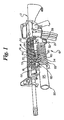
- FIG. 1 With general reference to FIG. 1 , there is shown a Colt® M203 grenade launcher 10, operatively integrated with an M16 rifle 12, equipped with the barrel latch safety 14 of the subject invention.
- the barrel latch safety 14 is shown affixed to a receiver 16 of the launcher 10, and in operative engagement with a barrel latch 18 thereof (i.e., a "lock-on" condition). It is to be understood that the barrel latch safety of the subject invention is not limited to operative engagement with the launcher of FIG. 1 .
- the grenade launcher 10 generally includes a barrel 20 supported, suspended, or otherwise engaged with the receiver 16 thereof.
- a handguard 22 substantially extends about a portion of the exterior surface 24 of the barrel 20.
- the launcher 10, more particularly the receiver 16, further includes, a firing mechanism 26 comprising the barrel latch 18, trigger 28, and trigger safety 30.
- the barrel 20 of the launcher 10 is disengagable from the receiver 16, more particularly a breech end 32 thereof, for translation with respect thereto, in furtherance of loading a munition, and/or discharging a casing of a munition.
- the subject barrel latch safety 14 is adapted to be secured to the launcher receiver 16 proximal to the launcher barrel latch 18, for translation with respect thereto, such that a latch receiving surface 34 thereof selectively intercepts a travel path for the launcher barrel latch 18, thereby preventing disengagement of the launcher barrel 20 from the launcher receiver 16 via unintended actuation of the launcher barrel latch 18.
- the barrel latch 18 of the grenade launcher 10 generally comprises an elongate member (e.g., a bar) 40 having a latch or latching surface 42 opposite a free end 44 thereof, the latch surface 42 intended to selectively engage a portion (e.g., a stop) 46 of the launcher barrel 20, as shown.
- the barrel latch 18 is pivotably secured by a shaft or pin 48, between its ends, to the launcher receiver 16 such that a portion of the free end 44 (i.e., an actuation surface 50) outwardly projects from a lateral surface (e.g., a sidewall) 52 of the receiver 16 (i.e., the actuation surface 50 is accessible for manipulation of the latch 18).
- Pivoting of the barrel latch 18 about a pivot axis of the shaft 48 as by "pushing" the actuation surface 50 of the free end 44 into closer proximity to the sidewall 52 of the launcher receiver 16, frees the latch surface 42 from engagement with the stop 46 of the launcher barrel 20 (note ghost lines indicating a disengaged condition for the barrel latch 18), thereby permitting translation of the barrel 20 relative to the receiver 16.
- the barrel latch safety generally comprises a body 60 having opposing end portions, more particularly, first 62 and second 64 opposing end portions, for the sake of convention, muzzle and breech end portions respectively, the first opposing end portion 62 of the body 60 being "forward" of the second opposing end portion 64.
- the device body 60 further, and generally, includes opposing surfaces, namely, first 66 (i.e., visible) and second 68 (i.e., non-visible) surfaces, see e.g., FIG. 2 .
- Each opposing end portion 62, 64 of the device body 60 preferably includes an aperture or slot 70 to facilitate affixation and retention of the device 14 to the launcher receiver 16, using, as shown, shouldered fasteners 72, or the like.
- the second surface 68 of the device body 60 will be, or is, adjacent the sidewall 52 of the receiver 16, more particularly, an exterior surface of same, see e.g., FIG. 2 .
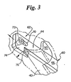
- the apertures 70 are advantageously configured to permit translation of the locking device 14 upon the fasteners 72, and thereby the receiver 16, namely, between the lock-on ( FIG. 4 and lock-off configurations of FIGS. 2 & 4 respectively.
- One such non-limiting aperture configuration, namely an oval, is shown in FIG. 3 , a maximum dimension thereof extending between the opposing end portions 62,64 of the device body 60.
- the first opposing end portion 62 of the device body 60 generally includes a locking plate or blade 74 having a first surface, more particularly, a visible latch receiving surface 76 adapted to operatively engage the free end 44 of the barrel latch 18.
- a second, non-visible surface 78 of the locking plate 74 (see e.g., FIGS. 2 & 4 ), opposite the first surface 76, is adapted to seat a detent 80 (e.g., a pin or ball) carried by the sidewall 52 of the receiver 16.
- the non-visible surface 78 of the locking plate 74 includes a pair of spaced apart dimples 82 for receipt and seating of the detent 80 at either a first 84 ( FIG. 2 ) or second 86 ( FIG. 4 ) position of the second surface 78 of the locking plate 74, that is to say, the lock-on and lock-off positions respectively.
- the latch receiving surface 76 preferably, but not necessarily, includes a ramped (e.g., beveled) portion so as to provide a sure interference fit for the locking device 14 relative to the barrel latch 18.
- the ramped portion of the latch receiving surface 76 may be effectively wedged between the free end 44 of the barrel latch 18 and the sidewall 52 of the receiver 16 to prohibit actuation of the barrel latch 18.
- the second opposing end portion 64 of the device body 60 preferably, as shown, has a segment configured so as to define a finger rest or grip 88. More generally, the second opposing end portion 64 of the device body 60 is to include a structure to facilitate translation (i.e., actuation) of the device 14 between the lock-on/lock-off conditions of FIGS. 2 & 4 respectively.
- the subject disclosure is in no way intended to be limiting of the means available to perform the recited function.
- the second opposing end portion 64 of the device body 60 may include a protuberance or the like, integral therewith (e.g., a ridge), or attachable thereto (e.g., a knob).
- a terminal end 90 of the second opposing end portion 64 of the device body 60 is configured to include a curve, bend, fold, crease, etc. (i.e., the terminal end 90 is not planar, or alternately stated, a substantial portion of the non-visible surface of the terminal end 90 of the second opposing end portion 64 does not contact the receiver sidewall 52).
- a not insubstantial amount of force must be imparted to the second opposing end portion 64 of the device body 60 so as to overcome the detent positioning of the device 14 relative to the receiver 16, whether in the lock-on or lock-off position/condition.
- a finger rest or hold 88 of large surface area is advantageous, and therefore desirable.
- FIGS. 2 & 4 Operation of the subject device is best appreciated by comparison of FIGS. 2 & 4 .
- the latch receiving surface 76 of the locking plate 74 is interposed between a portion of the free end 44 of the elongate member 40 of the barrel latch 18, and the sidewall 52 of the launcher receiver 16, and operatively retained in such condition due to receipt of the receiver detent 80 in the forward most dimple 82 of the non-visible surface 78 of the locking plate 74. Pivot motion of the barrel latch 18, and disengagement of the barrel 20 relative to the receiver 16 thereby, is prohibited.
- This invention disclosure provides preferred safety configurations, and defines preferred relationships and interrelationships between structures of the configuration, in addition to relationships and interrelationships between the subject device and the grenade launcher.
- This disclosure in many respects, is only illustrative. Changes may be made in details, particularly in matters of shape, size, material, and arrangement of parts without exceeding the scope of the invention. Accordingly, the scope of the invention is as defined in the language of the appended claim.
Landscapes
- Engineering & Computer Science (AREA)
- General Engineering & Computer Science (AREA)
- Toys (AREA)
Claims (14)
- Dispositif de sûreté pour verrou de canon (14) destiné à un verrou de canon de lance-grenades (18), dans lequel le verrou de canon de lance-grenades (18) fait saillie vers l'extérieur d'une surface externe (52) d'un récepteur de lance-grenades (16) afin d'être accessible à la manipulation, le dispositif de sûreté (14) comprenant un corps (60) ayant des parties d'extrémité opposées (62, 64), une première des parties d'extrémité opposées (62) du corps (60) comprenant une plaque de verrouillage (74), le dispositif de sûreté (14) étant adapté pour être fixé à la surface externe (52) du récepteur du lance-grenades (16) proche du verrou de canon du lance-grenades (18) pour translation par rapport à celui-ci de sorte qu'une partie de la plaque de verrouillage (74) intercepte un chemin de déplacement destiné au verrou de canon de lance-grenades (18), empêchant ainsi un désenclenchement d'un canon de lance-grenades (20) du récepteur du lance-grenades (16) par l'actionnement involontaire du verrou de canon du lance-grenades (18).
- Dispositif de sûreté (14) selon la revendication 1, dans lequel la plaque de verrouillage (74) comprend une première surface (76) et une deuxième surface (78) opposée à ladite première surface (76).
- Dispositif de sûreté (14) selon la revendication 2, dans lequel une partie de la première surface (76) de la plaque de verrouillage (74) comprend une surface de réception du verrou de canon.
- Dispositif de sûreté (14) selon la revendication 3, dans lequel la surface de réception du verrou de canon comprend une partie inclinée.
- Dispositif de sûreté (14) selon la revendication 3, dans lequel la deuxième surface (78) de la plaque de verrouillage (74) est adaptée pour enclencher co-opérativement une partie du récepteur du lance-grenades (16) de manière à résister à la translation.
- Dispositif de sûreté (14) selon la revendication 5, dans lequel la deuxième surface (78) de la plaque de verrouillage (74) est adaptée pour loger une butée (80).
- Dispositif de sûreté (14) selon la revendication 6, dans lequel la deuxième surface (78) de la plaque de verrouillage (74) est adaptée pour loger une détente (80) à une première et à une deuxième positions (84, 86) par rapport à celle-ci.
- Dispositif de sûreté (14) selon la revendication 7, dans lequel la deuxième surface (78) de la plaque de verrouillage (74) comprend des petites bosses séparées espacées (82).
- Dispositif de sûreté (14) selon la revendication 8, dans lequel les petites bosses séparées espacées (82) correspondent à la première et deuxième positions (84, 86) de la deuxième surface (78) de la plaque de verrouillage (74).
- Dispositif de sûreté (14) selon la revendication 5, dans lequel la deuxième des parties d'extrémité opposées (64) du corps (60) est configurée pour faciliter la translation du dispositif de sûreté (14).
- Dispositif de sûreté (14) selon la revendication 10, dans lequel la deuxième partie d'extrémité (64) se termine en un support de doigt (88).
- Dispositif de sûreté (14) selon la revendication 5, dans lequel une deuxième des parties d'extrémité opposées (64) du corps (60) comprend un moyen (88) pour actionner le dispositif de sûreté (14) entre une position verrouillée et une position déverrouillée.
- Dispositif de sûreté (14) selon la revendication 10, dans lequel chaque partie d'extrémité opposée desdites parties d'extrémité opposées (62, 64) du corps (60) comprend une fente (70).
- Lance-grenades comprenant :a. un canon (20) en enclenchement opérationnel avec un assemblage de récepteur (16), l'assemblage de récepteur (16) comprenant un verrou de canon pouvant pivoter (18) pour fixer le canon (20) dans une position opérationnelle par rapport à l'assemblage du récepteur ( 16); etb. un dispositif de sûreté (14) selon l'une quelconque des revendications précédentes, le dispositif de sûreté étant soutenu sur une surface externe de l'assemblage du récepteur (16) proche du verrou de canon pouvant pivoter (18) afin d'empêcher sélectivement le désenclenchement du canon (20) du récepteur (16) par l'actionnement involontaire du verrou de canon pouvant pivoter (18).
Applications Claiming Priority (3)
| Application Number | Priority Date | Filing Date | Title |
|---|---|---|---|
| US41749102P | 2002-10-10 | 2002-10-10 | |
| US417491P | 2002-10-10 | ||
| PCT/US2003/032312 WO2004033981A2 (fr) | 2002-10-10 | 2003-10-10 | Dispositif de verrouillage pour verrou de canon |
Publications (3)
| Publication Number | Publication Date |
|---|---|
| EP1556660A2 EP1556660A2 (fr) | 2005-07-27 |
| EP1556660A4 EP1556660A4 (fr) | 2010-08-04 |
| EP1556660B1 true EP1556660B1 (fr) | 2013-08-07 |
Family
ID=32094027
Family Applications (1)
| Application Number | Title | Priority Date | Filing Date |
|---|---|---|---|
| EP03776323.2A Expired - Lifetime EP1556660B1 (fr) | 2002-10-10 | 2003-10-10 | Dispositif de sûreté pour verrou de canon de lance-grenade |
Country Status (6)
| Country | Link |
|---|---|
| US (2) | US7328530B2 (fr) |
| EP (1) | EP1556660B1 (fr) |
| AU (1) | AU2003284092B8 (fr) |
| BR (1) | BR0314553A (fr) |
| CA (1) | CA2502291C (fr) |
| WO (1) | WO2004033981A2 (fr) |
Families Citing this family (17)
| Publication number | Priority date | Publication date | Assignee | Title |
|---|---|---|---|---|
| US8051595B2 (en) * | 2004-06-16 | 2011-11-08 | Colt Defense, Llc | Automatic or semi-automatic rifle |
| AT503135B1 (de) * | 2006-03-16 | 2007-08-15 | Rotay Marketing Consulting Nfg | Abschussvorrichtung für granaten |
| WO2010123605A2 (fr) * | 2009-01-28 | 2010-10-28 | Daniel Defense, Inc. | Ensemble garde-main et ensemble adaptateur de monture stanag |
| US8397414B2 (en) * | 2010-05-20 | 2013-03-19 | Ian Thomas Walters | Buttstock pre-adjustment block |
| US9599431B2 (en) * | 2011-01-17 | 2017-03-21 | RM Equipment, Inc. | Device for attachment to a profiled rail |
| KR20140022906A (ko) * | 2011-05-02 | 2014-02-25 | 콜트 디펜스 엘엘씨 | 모듈형 레일 시스템 및 모듈형 레일 시스템을 장착한 화기 |
| US8991091B2 (en) | 2013-01-14 | 2015-03-31 | RM Equipment, Inc. | Universal launcher system |
| CN104482801B (zh) * | 2014-11-05 | 2016-02-24 | 重庆建设工业(集团)有限责任公司 | 一种枪械枪身 |
| AU2015355127B2 (en) * | 2014-12-01 | 2020-02-06 | Wilcox Industries Corp. | Modular grenade launcher system |
| US9464866B1 (en) * | 2015-10-16 | 2016-10-11 | Vega Force International Corp. | Toy gun assembly structure |
| US10113825B2 (en) * | 2016-05-10 | 2018-10-30 | Kudzu Arms, Llc | Systems and methods for attaching a secondary firearm to a primary firearm |
| US10234222B2 (en) * | 2016-08-09 | 2019-03-19 | Gonzalo Couce | Single 40 mm projectile launcher |
| US10119781B1 (en) | 2017-05-08 | 2018-11-06 | Wilcox Industries Corp. | Grenade launcher and pivot mechanism for same |
| US11187474B2 (en) * | 2018-01-09 | 2021-11-30 | William E. Masters | Compact shotgun, multipurpose mount, and trigger assembly |
| US11035646B2 (en) | 2018-12-21 | 2021-06-15 | Wilcox Industries Corp. | Grenade launcher with modular interface |
| WO2021101473A1 (fr) * | 2019-11-22 | 2021-05-27 | Bahtiyar Tasyagan | Mécanisme de retrait et d'installation rapides pour canons d'armes à feu |
| US11543194B2 (en) * | 2020-10-07 | 2023-01-03 | Rory Berger | Projectile launcher with barrel breech lock mechanism |
Family Cites Families (17)
| Publication number | Priority date | Publication date | Assignee | Title |
|---|---|---|---|---|
| US2981154A (en) * | 1960-01-07 | 1961-04-25 | Aircraft Armaments Inc | Safety interlock for machine gun barrel |
| US3034407A (en) * | 1961-04-20 | 1962-05-15 | Darsie Burns | Barrel safety latch |
| US3365828A (en) * | 1965-06-25 | 1968-01-30 | Olin Mathieson | Grenade launcher for attachment to a rifle |
| US3332162A (en) * | 1965-12-22 | 1967-07-25 | Honeywell Inc | Combined rifle and grenade launcher |
| US3507067A (en) * | 1967-12-14 | 1970-04-21 | Colt S Inc | Grenade launcher having a rotatable forwardly sliding barrel and removable firing mechanism |
| US3561149A (en) * | 1968-10-09 | 1971-02-09 | Warren A Center | Pistol with means actuating the barrel latch and setting the trigger mechanism and safety |
| US3557482A (en) * | 1969-02-04 | 1971-01-26 | Us Army | Means for controlling the headspacing of grenade cartridges in a single-shot launcher |
| US3641691A (en) * | 1969-05-21 | 1972-02-15 | Us Army | Grenade launcher with pivotally mounted barrel |
| DE1944625C3 (de) * | 1969-09-03 | 1973-01-04 | Heckler & Koch Gmbh, 7238 Oberndorf | An einer Handfeuerwaffe befestigbarer Granatwerfer |
| US3967402A (en) * | 1975-01-22 | 1976-07-06 | The United States Of America As Represented By The Scretary Of The Army | Manually-operated firearm with forward-moving barrel and pivoted breech block |
| US4689911A (en) * | 1984-06-04 | 1987-09-01 | Napco Industries, Inc. | Grenade launcher attachment for infantry weapon |
| US4733489A (en) * | 1984-11-14 | 1988-03-29 | R/M Equipment, Inc. | Apparatus for reconfiguring automatic rifle to include grenade launching function |
| US4833970A (en) * | 1987-08-31 | 1989-05-30 | Gary Wilhelm | Submachine gun |
| FR2734629B1 (fr) * | 1995-05-23 | 1997-07-25 | Giat Ind Sa | Accessoire d'arme a feu portative |
| CA2247234C (fr) * | 1997-09-11 | 2004-10-26 | R/M Equipment, Inc. | Methode et dispositif de fixation d'un accessoire additionnel a une arme a feu non modifiee |
| DE19925864C1 (de) * | 1999-06-07 | 2000-08-10 | Heckler & Koch Gmbh | Anbau-Granatwerfer |
| US6397505B1 (en) * | 1999-12-02 | 2002-06-04 | Virgin Valley Custom Guns, Llc | Cartridge casing ejector for a firearm |
-
2003
- 2003-10-10 CA CA2502291A patent/CA2502291C/fr not_active Expired - Fee Related
- 2003-10-10 AU AU2003284092A patent/AU2003284092B8/en not_active Ceased
- 2003-10-10 EP EP03776323.2A patent/EP1556660B1/fr not_active Expired - Lifetime
- 2003-10-10 US US10/530,732 patent/US7328530B2/en not_active Expired - Fee Related
- 2003-10-10 BR BR0314553-0A patent/BR0314553A/pt not_active Application Discontinuation
- 2003-10-10 WO PCT/US2003/032312 patent/WO2004033981A2/fr not_active Ceased
-
2008
- 2008-02-12 US US12/029,974 patent/US7891130B2/en not_active Expired - Lifetime
Also Published As
| Publication number | Publication date |
|---|---|
| AU2003284092A1 (en) | 2004-05-04 |
| EP1556660A4 (fr) | 2010-08-04 |
| US7891130B2 (en) | 2011-02-22 |
| WO2004033981A3 (fr) | 2005-05-12 |
| EP1556660A2 (fr) | 2005-07-27 |
| US7328530B2 (en) | 2008-02-12 |
| AU2003284092B8 (en) | 2010-03-18 |
| CA2502291A1 (fr) | 2004-04-22 |
| AU2003284092B2 (en) | 2009-11-19 |
| CA2502291C (fr) | 2011-05-17 |
| BR0314553A (pt) | 2005-08-23 |
| US20060201044A1 (en) | 2006-09-14 |
| US20110016765A1 (en) | 2011-01-27 |
| WO2004033981A2 (fr) | 2004-04-22 |
Similar Documents
| Publication | Publication Date | Title |
|---|---|---|
| US7891130B2 (en) | Barrel latch locking device | |
| US12372316B2 (en) | Takedown lever, takedown safety, and trigger shoe | |
| US6553706B1 (en) | Sear and step trigger assembly having a secondary sear block | |
| US7421937B1 (en) | Modular insertion trigger method and apparatus | |
| US6481145B2 (en) | Grenade launcher | |
| US9494378B2 (en) | Ambidextrously operated bolt catch assembly | |
| US6560909B2 (en) | Manual safety for linear striker fired semi-automatic or automatic pistols | |
| US9500421B1 (en) | Firearm charging handle | |
| US20060123683A1 (en) | Ambidextrous magazine catch for firearms | |
| US20180135929A1 (en) | Trigger mechanism for a firearm | |
| US9341442B1 (en) | Knife mount for a firearm | |
| US5903994A (en) | Normally-on safety on a pistol, and method of converting a pistol to include a normally-on safety | |
| US9175916B2 (en) | Trigger assembly with a device to prevent accidental firearm discharge when dropped | |
| US12140405B2 (en) | Device for attaching a sight to a handgun | |
| US20190271518A1 (en) | Trigger mechanism for a firearm | |
| US12181237B2 (en) | Trigger return and safety mechanism | |
| US11656047B1 (en) | Chamber flag | |
| US10890396B2 (en) | Slotted trigger actuation | |
| US6119387A (en) | Trigger safety mechanism | |
| WO2018023076A1 (fr) | Système d'étui pour crosse d'arme à feu double | |
| US20170307314A1 (en) | Modified break-action firearm | |
| US20250137743A1 (en) | Trigger Mechanism for a Firearm | |
| US20200132405A1 (en) | Trigger Mechanism For A Firearm | |
| US20250230997A1 (en) | Trigger assembly for a firearm | |
| US5000076A (en) | Automatic safety release for firearms |
Legal Events
| Date | Code | Title | Description |
|---|---|---|---|
| PUAI | Public reference made under article 153(3) epc to a published international application that has entered the european phase |
Free format text: ORIGINAL CODE: 0009012 |
|
| 17P | Request for examination filed |
Effective date: 20050502 |
|
| AK | Designated contracting states |
Kind code of ref document: A2 Designated state(s): AT BE BG CH CY CZ DE DK EE ES FI FR GB GR HU IE IT LI LU MC NL PT RO SE SI SK TR |
|
| AX | Request for extension of the european patent |
Extension state: AL LT LV MK |
|
| DAX | Request for extension of the european patent (deleted) | ||
| A4 | Supplementary search report drawn up and despatched |
Effective date: 20100702 |
|
| RIC1 | Information provided on ipc code assigned before grant |
Ipc: F41A 21/48 20060101AFI20100628BHEP |
|
| 17Q | First examination report despatched |
Effective date: 20101006 |
|
| REG | Reference to a national code |
Ref country code: DE Ref legal event code: R079 Ref document number: 60344678 Country of ref document: DE Free format text: PREVIOUS MAIN CLASS: F41A0003000000 Ipc: F41C0027060000 |
|
| RIC1 | Information provided on ipc code assigned before grant |
Ipc: F41C 27/06 20060101AFI20120619BHEP Ipc: F41A 21/48 20060101ALI20120619BHEP |
|
| GRAP | Despatch of communication of intention to grant a patent |
Free format text: ORIGINAL CODE: EPIDOSNIGR1 |
|
| GRAP | Despatch of communication of intention to grant a patent |
Free format text: ORIGINAL CODE: EPIDOSNIGR1 |
|
| GRAS | Grant fee paid |
Free format text: ORIGINAL CODE: EPIDOSNIGR3 |
|
| GRAA | (expected) grant |
Free format text: ORIGINAL CODE: 0009210 |
|
| AK | Designated contracting states |
Kind code of ref document: B1 Designated state(s): AT BE BG CH CY CZ DE DK EE ES FI FR GB GR HU IE IT LI LU MC NL PT RO SE SI SK TR |
|
| REG | Reference to a national code |
Ref country code: GB Ref legal event code: FG4D |
|
| REG | Reference to a national code |
Ref country code: CH Ref legal event code: EP Ref country code: AT Ref legal event code: REF Ref document number: 625936 Country of ref document: AT Kind code of ref document: T Effective date: 20130815 |
|
| REG | Reference to a national code |
Ref country code: IE Ref legal event code: FG4D |
|
| REG | Reference to a national code |
Ref country code: DE Ref legal event code: R096 Ref document number: 60344678 Country of ref document: DE Effective date: 20131002 |
|
| REG | Reference to a national code |
Ref country code: AT Ref legal event code: MK05 Ref document number: 625936 Country of ref document: AT Kind code of ref document: T Effective date: 20130807 |
|
| REG | Reference to a national code |
Ref country code: NL Ref legal event code: VDEP Effective date: 20130807 |
|
| PG25 | Lapsed in a contracting state [announced via postgrant information from national office to epo] |
Ref country code: CY Free format text: LAPSE BECAUSE OF FAILURE TO SUBMIT A TRANSLATION OF THE DESCRIPTION OR TO PAY THE FEE WITHIN THE PRESCRIBED TIME-LIMIT Effective date: 20130703 Ref country code: SE Free format text: LAPSE BECAUSE OF FAILURE TO SUBMIT A TRANSLATION OF THE DESCRIPTION OR TO PAY THE FEE WITHIN THE PRESCRIBED TIME-LIMIT Effective date: 20130807 Ref country code: AT Free format text: LAPSE BECAUSE OF FAILURE TO SUBMIT A TRANSLATION OF THE DESCRIPTION OR TO PAY THE FEE WITHIN THE PRESCRIBED TIME-LIMIT Effective date: 20130807 Ref country code: PT Free format text: LAPSE BECAUSE OF FAILURE TO SUBMIT A TRANSLATION OF THE DESCRIPTION OR TO PAY THE FEE WITHIN THE PRESCRIBED TIME-LIMIT Effective date: 20131209 |
|
| PG25 | Lapsed in a contracting state [announced via postgrant information from national office to epo] |
Ref country code: GR Free format text: LAPSE BECAUSE OF FAILURE TO SUBMIT A TRANSLATION OF THE DESCRIPTION OR TO PAY THE FEE WITHIN THE PRESCRIBED TIME-LIMIT Effective date: 20131108 Ref country code: FI Free format text: LAPSE BECAUSE OF FAILURE TO SUBMIT A TRANSLATION OF THE DESCRIPTION OR TO PAY THE FEE WITHIN THE PRESCRIBED TIME-LIMIT Effective date: 20130807 Ref country code: NL Free format text: LAPSE BECAUSE OF FAILURE TO SUBMIT A TRANSLATION OF THE DESCRIPTION OR TO PAY THE FEE WITHIN THE PRESCRIBED TIME-LIMIT Effective date: 20130807 Ref country code: BE Free format text: LAPSE BECAUSE OF FAILURE TO SUBMIT A TRANSLATION OF THE DESCRIPTION OR TO PAY THE FEE WITHIN THE PRESCRIBED TIME-LIMIT Effective date: 20130807 Ref country code: SI Free format text: LAPSE BECAUSE OF FAILURE TO SUBMIT A TRANSLATION OF THE DESCRIPTION OR TO PAY THE FEE WITHIN THE PRESCRIBED TIME-LIMIT Effective date: 20130807 |
|
| PG25 | Lapsed in a contracting state [announced via postgrant information from national office to epo] |
Ref country code: CY Free format text: LAPSE BECAUSE OF FAILURE TO SUBMIT A TRANSLATION OF THE DESCRIPTION OR TO PAY THE FEE WITHIN THE PRESCRIBED TIME-LIMIT Effective date: 20130807 |
|
| PG25 | Lapsed in a contracting state [announced via postgrant information from national office to epo] |
Ref country code: CZ Free format text: LAPSE BECAUSE OF FAILURE TO SUBMIT A TRANSLATION OF THE DESCRIPTION OR TO PAY THE FEE WITHIN THE PRESCRIBED TIME-LIMIT Effective date: 20130807 Ref country code: EE Free format text: LAPSE BECAUSE OF FAILURE TO SUBMIT A TRANSLATION OF THE DESCRIPTION OR TO PAY THE FEE WITHIN THE PRESCRIBED TIME-LIMIT Effective date: 20130807 Ref country code: RO Free format text: LAPSE BECAUSE OF FAILURE TO SUBMIT A TRANSLATION OF THE DESCRIPTION OR TO PAY THE FEE WITHIN THE PRESCRIBED TIME-LIMIT Effective date: 20130807 Ref country code: DK Free format text: LAPSE BECAUSE OF FAILURE TO SUBMIT A TRANSLATION OF THE DESCRIPTION OR TO PAY THE FEE WITHIN THE PRESCRIBED TIME-LIMIT Effective date: 20130807 Ref country code: SK Free format text: LAPSE BECAUSE OF FAILURE TO SUBMIT A TRANSLATION OF THE DESCRIPTION OR TO PAY THE FEE WITHIN THE PRESCRIBED TIME-LIMIT Effective date: 20130807 |
|
| PG25 | Lapsed in a contracting state [announced via postgrant information from national office to epo] |
Ref country code: ES Free format text: LAPSE BECAUSE OF FAILURE TO SUBMIT A TRANSLATION OF THE DESCRIPTION OR TO PAY THE FEE WITHIN THE PRESCRIBED TIME-LIMIT Effective date: 20130807 Ref country code: IT Free format text: LAPSE BECAUSE OF FAILURE TO SUBMIT A TRANSLATION OF THE DESCRIPTION OR TO PAY THE FEE WITHIN THE PRESCRIBED TIME-LIMIT Effective date: 20130807 Ref country code: MC Free format text: LAPSE BECAUSE OF FAILURE TO SUBMIT A TRANSLATION OF THE DESCRIPTION OR TO PAY THE FEE WITHIN THE PRESCRIBED TIME-LIMIT Effective date: 20130807 |
|
| REG | Reference to a national code |
Ref country code: CH Ref legal event code: PL |
|
| PLBE | No opposition filed within time limit |
Free format text: ORIGINAL CODE: 0009261 |
|
| STAA | Information on the status of an ep patent application or granted ep patent |
Free format text: STATUS: NO OPPOSITION FILED WITHIN TIME LIMIT |
|
| 26N | No opposition filed |
Effective date: 20140508 |
|
| GBPC | Gb: european patent ceased through non-payment of renewal fee |
Effective date: 20131107 |
|
| REG | Reference to a national code |
Ref country code: IE Ref legal event code: MM4A |
|
| PG25 | Lapsed in a contracting state [announced via postgrant information from national office to epo] |
Ref country code: CH Free format text: LAPSE BECAUSE OF NON-PAYMENT OF DUE FEES Effective date: 20131031 Ref country code: LI Free format text: LAPSE BECAUSE OF NON-PAYMENT OF DUE FEES Effective date: 20131031 |
|
| REG | Reference to a national code |
Ref country code: DE Ref legal event code: R119 Ref document number: 60344678 Country of ref document: DE Effective date: 20140501 |
|
| REG | Reference to a national code |
Ref country code: FR Ref legal event code: ST Effective date: 20140630 |
|
| PG25 | Lapsed in a contracting state [announced via postgrant information from national office to epo] |
Ref country code: FR Free format text: LAPSE BECAUSE OF NON-PAYMENT OF DUE FEES Effective date: 20131031 Ref country code: DE Free format text: LAPSE BECAUSE OF NON-PAYMENT OF DUE FEES Effective date: 20140501 |
|
| PG25 | Lapsed in a contracting state [announced via postgrant information from national office to epo] |
Ref country code: IE Free format text: LAPSE BECAUSE OF NON-PAYMENT OF DUE FEES Effective date: 20131010 |
|
| PG25 | Lapsed in a contracting state [announced via postgrant information from national office to epo] |
Ref country code: GB Free format text: LAPSE BECAUSE OF NON-PAYMENT OF DUE FEES Effective date: 20131107 |
|
| PG25 | Lapsed in a contracting state [announced via postgrant information from national office to epo] |
Ref country code: TR Free format text: LAPSE BECAUSE OF FAILURE TO SUBMIT A TRANSLATION OF THE DESCRIPTION OR TO PAY THE FEE WITHIN THE PRESCRIBED TIME-LIMIT Effective date: 20130807 |
|
| PG25 | Lapsed in a contracting state [announced via postgrant information from national office to epo] |
Ref country code: BG Free format text: LAPSE BECAUSE OF FAILURE TO SUBMIT A TRANSLATION OF THE DESCRIPTION OR TO PAY THE FEE WITHIN THE PRESCRIBED TIME-LIMIT Effective date: 20130807 Ref country code: HU Free format text: LAPSE BECAUSE OF FAILURE TO SUBMIT A TRANSLATION OF THE DESCRIPTION OR TO PAY THE FEE WITHIN THE PRESCRIBED TIME-LIMIT; INVALID AB INITIO Effective date: 20031010 Ref country code: LU Free format text: LAPSE BECAUSE OF NON-PAYMENT OF DUE FEES Effective date: 20131010 |