EP1556777B1 - System und verfahren zur synchronisierung der konfiguration verteilter netzwerkverwaltungsanwendungen - Google Patents
System und verfahren zur synchronisierung der konfiguration verteilter netzwerkverwaltungsanwendungen Download PDFInfo
- Publication number
- EP1556777B1 EP1556777B1 EP03734453.8A EP03734453A EP1556777B1 EP 1556777 B1 EP1556777 B1 EP 1556777B1 EP 03734453 A EP03734453 A EP 03734453A EP 1556777 B1 EP1556777 B1 EP 1556777B1
- Authority
- EP
- European Patent Office
- Prior art keywords
- network
- network management
- application
- management object
- configuration information
- Prior art date
- Legal status (The legal status is an assumption and is not a legal conclusion. Google has not performed a legal analysis and makes no representation as to the accuracy of the status listed.)
- Expired - Lifetime
Links
- 238000000034 method Methods 0.000 title claims description 39
- 238000007726 management method Methods 0.000 claims description 121
- 230000008569 process Effects 0.000 claims description 21
- 238000013070 change management Methods 0.000 claims description 19
- 230000008859 change Effects 0.000 claims description 12
- 238000012545 processing Methods 0.000 claims description 7
- 239000000835 fiber Substances 0.000 claims 2
- 230000006870 function Effects 0.000 description 22
- 238000012546 transfer Methods 0.000 description 16
- 230000006854 communication Effects 0.000 description 13
- 238000004891 communication Methods 0.000 description 12
- 238000012544 monitoring process Methods 0.000 description 11
- 230000001360 synchronised effect Effects 0.000 description 9
- 230000000694 effects Effects 0.000 description 7
- 238000004458 analytical method Methods 0.000 description 5
- 230000007246 mechanism Effects 0.000 description 5
- 230000009471 action Effects 0.000 description 4
- 238000013459 approach Methods 0.000 description 4
- 238000013480 data collection Methods 0.000 description 3
- 230000010354 integration Effects 0.000 description 3
- 230000003068 static effect Effects 0.000 description 3
- 230000006399 behavior Effects 0.000 description 2
- 238000013523 data management Methods 0.000 description 2
- 230000001419 dependent effect Effects 0.000 description 2
- 238000009826 distribution Methods 0.000 description 2
- 238000012986 modification Methods 0.000 description 2
- 230000004048 modification Effects 0.000 description 2
- 238000013515 script Methods 0.000 description 2
- 238000003860 storage Methods 0.000 description 2
- 230000002776 aggregation Effects 0.000 description 1
- 238000004220 aggregation Methods 0.000 description 1
- 230000008901 benefit Effects 0.000 description 1
- 238000004140 cleaning Methods 0.000 description 1
- 238000012937 correction Methods 0.000 description 1
- 238000013479 data entry Methods 0.000 description 1
- 230000007123 defense Effects 0.000 description 1
- 238000013461 design Methods 0.000 description 1
- 230000007613 environmental effect Effects 0.000 description 1
- 230000008676 import Effects 0.000 description 1
- 238000012423 maintenance Methods 0.000 description 1
- 238000004519 manufacturing process Methods 0.000 description 1
- 230000003278 mimic effect Effects 0.000 description 1
- 201000002266 mite infestation Diseases 0.000 description 1
- 238000012806 monitoring device Methods 0.000 description 1
- 230000000644 propagated effect Effects 0.000 description 1
- 230000004044 response Effects 0.000 description 1
- 238000012552 review Methods 0.000 description 1
- 230000009885 systemic effect Effects 0.000 description 1
- 238000012360 testing method Methods 0.000 description 1
Images





Classifications
-
- H—ELECTRICITY
- H04—ELECTRIC COMMUNICATION TECHNIQUE
- H04L—TRANSMISSION OF DIGITAL INFORMATION, e.g. TELEGRAPHIC COMMUNICATION
- H04L41/00—Arrangements for maintenance, administration or management of data switching networks, e.g. of packet switching networks
- H04L41/08—Configuration management of networks or network elements
- H04L41/0803—Configuration setting
- H04L41/0813—Configuration setting characterised by the conditions triggering a change of settings
- H04L41/082—Configuration setting characterised by the conditions triggering a change of settings the condition being updates or upgrades of network functionality
-
- H—ELECTRICITY
- H04—ELECTRIC COMMUNICATION TECHNIQUE
- H04L—TRANSMISSION OF DIGITAL INFORMATION, e.g. TELEGRAPHIC COMMUNICATION
- H04L41/00—Arrangements for maintenance, administration or management of data switching networks, e.g. of packet switching networks
- H04L41/08—Configuration management of networks or network elements
- H04L41/085—Retrieval of network configuration; Tracking network configuration history
- H04L41/0853—Retrieval of network configuration; Tracking network configuration history by actively collecting configuration information or by backing up configuration information
- H04L41/0856—Retrieval of network configuration; Tracking network configuration history by actively collecting configuration information or by backing up configuration information by backing up or archiving configuration information
-
- H—ELECTRICITY
- H04—ELECTRIC COMMUNICATION TECHNIQUE
- H04L—TRANSMISSION OF DIGITAL INFORMATION, e.g. TELEGRAPHIC COMMUNICATION
- H04L41/00—Arrangements for maintenance, administration or management of data switching networks, e.g. of packet switching networks
- H04L41/08—Configuration management of networks or network elements
- H04L41/0876—Aspects of the degree of configuration automation
- H04L41/0886—Fully automatic configuration
-
- H—ELECTRICITY
- H04—ELECTRIC COMMUNICATION TECHNIQUE
- H04L—TRANSMISSION OF DIGITAL INFORMATION, e.g. TELEGRAPHIC COMMUNICATION
- H04L67/00—Network arrangements or protocols for supporting network services or applications
- H04L67/01—Protocols
- H04L67/12—Protocols specially adapted for proprietary or special-purpose networking environments, e.g. medical networks, sensor networks, networks in vehicles or remote metering networks
- H04L67/125—Protocols specially adapted for proprietary or special-purpose networking environments, e.g. medical networks, sensor networks, networks in vehicles or remote metering networks involving control of end-device applications over a network
-
- H—ELECTRICITY
- H04—ELECTRIC COMMUNICATION TECHNIQUE
- H04L—TRANSMISSION OF DIGITAL INFORMATION, e.g. TELEGRAPHIC COMMUNICATION
- H04L67/00—Network arrangements or protocols for supporting network services or applications
- H04L67/34—Network arrangements or protocols for supporting network services or applications involving the movement of software or configuration parameters
-
- H—ELECTRICITY
- H04—ELECTRIC COMMUNICATION TECHNIQUE
- H04L—TRANSMISSION OF DIGITAL INFORMATION, e.g. TELEGRAPHIC COMMUNICATION
- H04L41/00—Arrangements for maintenance, administration or management of data switching networks, e.g. of packet switching networks
- H04L41/02—Standardisation; Integration
- H04L41/0213—Standardised network management protocols, e.g. simple network management protocol [SNMP]
Definitions
- the present invention relates to network management. More specifically, the present invention is an automated change management system and method to manage diverse management functions across a network in an automated fashion.
- Networks carry voice and data communications for communication, entertainment, business, and defense endeavors to name but a few.
- Management comprises configuring devices for connection to the network, monitoring and reporting on network and device loads, and managing device failure.
- a device is often managed by a variety of applications depending on the function to be managed.
- the workload of a device may be managed by application A supplied by vendor A and the configuration of a device may be managed by application B supplied by vendor B.
- application A is configured via a script to manage device A and reports its results to a workload database.
- Application B is configured using a text file to manage the configuration of device B and reports its results to a configuration database.
- applications A and B cannot directly communicate with each other or share data.
- network devices In modern day networks such as wireless networks, intranets or the Internet, there are a number of network devices of various types. Such network devices may be workstations, routers, servers, and a wide variety of other smart devices that appear on networks. Network management tools have evolved to manage these devices. As networks have increased in size and complexity, network management functions have become increasingly resource intensive.
- Network management comprises a number of functions, including (but without limitation) fault management, configuration management, performance management, security management, inventory management and cost management. Of these functions, configuration management is of particular importance as it affects in varying degree the effectiveness of the other network management systems in managing all of the other functions.
- Most devices and applications on a network are designed to be configured, thus broadening the applications for which a particular object can be used.
- the information comprising an object's configuration is both object and context dependent. That is, the configuration of a device may depend on the device, where in a network it is installed, what it is connected to, what applications it is intended to run, and the like.
- the configuration of the various objects comprising the network must be known at all times. An unplanned change in the configuration of a router, for example, may cause the network performance to deteriorate or to fail altogether, may result in increased error reporting and error correction processing time, and cause the network operator to expend resources to locate and correct the configuration error.
- Network management tools have been developed to detect changes in the configurations of critical network components. These tools monitor the configuration files of such objects, issue alarms when a change is detected, and offer manual or automatic restoration of the changed configuration file to a file known to be good.
- current configuration monitoring tools are reactionary. Such tools can determine that a configuration has changed, but cannot initiate a reconfiguration of specific devices or applications on the network or sub-network, or relate the configuration of one device on a network to another device on that network without human intervention. Rather, many traditional network management systems are maintained by hand-entering device lists into individual network management applications with no common-ties between the different applications.
- a network management application it is desirable for a network management application to know the configuration of each configurable device that such network management application is managing. This is accomplished by the network management application polling the managed devices and keeping a record of the polled data.
- networks with a large number of network management applications have difficulty synchronizing against a single inventory of devices and synchronizing device status over all of the network management applications.
- the network management applications are typically from diverse vendors and may not be able to communicate with each other. The result is that over the network, the data used to manage the configuration of network devices and network device polling applications is not current, and becomes less current (more asynchronous) as time goes on.
- U.S. Patent 5,785,083 ('083 Patent) to Singh, et al. entitled “Method And System For Sharing Information Between Network Managers,” discloses a technique for managing a network by sharing information between distributed network managers that manage a different portion of a large network. Databases in the different network managers can be synchronized with each other. The information that is shared is to be used by an end-user who monitors the network and takes corrective action when necessary.
- U.S. Patent 6,295,558 to Davis, et. al. , entitled “Automatic Status Polling Failover For Devices In A Distributed Network Management Hierarchy,” discloses an automatic failover methodology whereby a central control unit, such as a management station, will automatically takeover interface status polling of objects of a collection station that is temporarily unreachable.
- the '558 Patent teaches a failover methodology that reassigns polling responsibility from a failed collection station to a central control unit (such as a management station).
- a polling application at the central control unit obtains the topology of the failed collection station and performs polling until the polling station returns to operational status.
- US Patent 6,128,656 describes a system for updating a memory storing configuration information of a network element. The described operation of the system is based on traps that are generated by the network element. A network management device may poll a network element for trap information.
- EP 1 039 685 describes a method and apparatus for managing IP addressing in a network and effectively synchronizing communication between a central database and one or more servers.
- the server manager polls periodically the central database for any changes in configuration made to the network.
- the present application is drawn to at least address the problem of maintaining the configuration information synchronization of network devices in real time.
- EP 1 039 685 does not directly address this problem.
- WO 02/39351 A2 focuses in its disclosure on how to propagate a configuration change of an object stored in a registry to the other registries in a network using a master registry as means to propagate such a change.
- Objects of the present invention are a system as claimed in claim 1 and a method as claimed in claim 13 for managing and synchronizing network management applications from a common source.
- a change management process is automated by employing a real time two way communications model that permits a central database comprising the latest network management software and configuration to effect changes on all or some network management applications and systems in the field. Preferred embodiments are covered by the dependent claims.
- a change management engine synchronizes the configuration of distributed network management applications, as well as synchronize device status from those same distributed network management applications with a central database.
- “Change management” as used in this context means the process by which network management poller and aggregation applications are synchronized to the exact configurations of the devices they monitor in real-time without human intervention.
- the network can be a wired, or wireless network.
- embodiments of the present invention operate on an intranet, the Internet, or any other wired or wireless network that is to be managed as an entity. These embodiments operate in an application-diverse environment allowing the synchronization of networks that use applications of different vendors to perform various network management functions.
- the change management process is automated by employing a real time two way communications model that permits a central database comprising the latest network management software and configuration to effect changes on all or some network management applications and systems in the field.
- field systems also affect the central database by transmitting polled information into that database.
- Each network device is entered into a central database one time.
- this embodiment of the present invention handles all of the processes associated with configuring different and distributed network management systems and applications in the field.
- this embodiment of the present invention acts as a manager of other system managers in order to insure that all network management applications are synchronized across the network and binds many disparate functions of change management under one control model. Further, automating the configuration process reduces the risk that human error will disrupt the monitoring of critical systems.
- the process of handing over tasks of a failed monitoring device is managed in real-time fail over capability.
- This embodiment allows a single graphical user interface to be the means of monitoring a plurality of devices over the network.
- the plurality of devices is polled by any number of different servers and applications with responses from the polling reported via Simple Network Management Protocol (SNMP) to a central database.
- SNMP Simple Network Management Protocol
- NMS software products are referred to by their product names, which include the following:
- NMS operations station 120 is linked to a central database 100.
- Central database 100 comprises a device inventory database (DIDB) 105 and the network database (NDB) 110.
- the DIDB 105 stores configuration data for applications used to manage the network management system (NMS). For each sub-network managed by network management system, configuration data for devices on that sub-network are acquired by the associated poller server (for example, poller server 155 ), aggregated by the associated data aggregator (for example, data aggregator 135 ), and stored in the NDB 110.
- poller server for example, poller server 155
- data aggregator for example, data aggregator 135
- Central database 100 is linked to data aggregators 135, 145.
- Data aggregators 135 and 145 are linked, respectively, to NMS poller servers 155 and 165.
- NMS poller server 155 monitors sub-network 170
- NMS poller server 165 monitors sub-network 180.
- Sub-network 170 comprises devices 172, 174, and 176
- sub-network 180 comprises devices 182, 184, and 186.
- a "device” comprises a router, a switch, a modem, a server, or other configurable device and a software application. For ease of discussion, only two sub-networks have been illustrated in Figure 1 , but this is not meant as a limitation.
- NMS poller server 155 and NMS poller server 165 are linked to each other to create redundancy should one of the NMS poller servers fail. Additionally, for purposes of illustration and not as a limitation only two NMS poller server/data aggregator pairs are shown in Figure 1 . As will be apparent to those skilled in the art of the present invention, a plurality of NMS poller server/data aggregator pairs may be used to manage either sub-network.
- Each NMS poller server/data aggregator pair manages the sub-network to which it is assigned by polling the sub-network for relevant data.
- the particular tasks performed by a NMS poller server depend on the application software running on that server. Typical tasks include monitoring network devices for changes in configuration, performance, load, and environmental parameters, analyzing the data received from network devices, and sending the data to the central database 100 for further processing by NMS operations station 120.
- NMS operations station 120 the management of the NMS poller servers and data aggregators is through NMS operations station 120.
- the NMS operations station 120 is monitored by human operators who evaluate events reported to the central database and make decisions about problem resolution.
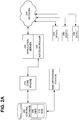
- the central database 200 (comprising DIDB 205 and NDB 210 ) is linked to core engine 215.
- Core engine 215 is linked to auto controller 220.
- Autocontroller 220 is co-located on an application server 225.
- Application server 225 is linked to one or more devices 230, 235, and 240 over network 250.
- Devices 230, 235, and 240 comprise configurable devices and applications.
- Application server 225 manages these devices according to the task to which application server 225 is assigned.
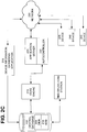
- application server 225 comprises a device information gathering application (as illustrated in Figure 2B ). In an alternate embodiment, the device gathering function is performed by a device information gathering application 270 that is not operated by application server 225 (as illustrated in Figure 2C ). As will be apparent to those skilled in the art, application server 225 may implement one of a number of network management tools without departing from the scope of the present invention which is defined in the appended claims. By way of illustration, application server 225 may be a reporting engine, a network portal, or an access control server.
- autocontroller 220 resides on application server 225.
- autocontroller 220 comprises a discrete functional component that is linked to application server 225.
- Autocontroller 220 manages, configures, and monitors all of the applications running on application server 225.
- Core engine 215 acts as the hub of the network management system configuration control functions. While core engine 215 is illustrated in Figures 2A , 2B , and 2C as a stand-alone component, the invention is not so limited. As will be appreciated by those skilled in the art, the functions of core engine 215 may be integrated with other network management functions without departing from the scope of the present invention which is defined by the appended claims.
- Core engine 215 reads device, site, polling, and configuration data from the DIDB 205, analyzes configuration data, builds application configuration files when needed, updates the DIDB 210 with the most current data, schedules device polling, and manages and monitors auto controller 220. Together, the core engine 215 and autocontroller 220 provide an existing network management system with the capability to automate the change management process in real-time.
- the autocontroller resides on each server that contains network management applications requiring core engine control.
- the autocontroller installs updated configuration files, launches and restarts applications, executes shell commands, parses and analyzes output files, returns any requested results back to be the core engine, and backs up another autocontroller (a "buddy").
- an autocontroller is capable of performing the functions of its buddy autocontroller should the buddy autocontroller experience a failure.
- each autocontroller comprises redundancy features to determine when the assigned buddy autocontroller fails or becomes unreachable. While Figures 2A , 2B , and 2C illustrate a single autocontroller managing a single application server, the present invention is not so limited. Any number of autocontrollers may each be paired with an application server under the control of a core engine to implement a change management system on any size network.
- the network management systems illustrated in Figure 1 and Figures 2A , 2B, and 2C are, of course, simplified views of the architecture of a functioning NMS. What these views illustrate is that the addition of the elements of the change management system of the present invention significantly increases the ability of NMS to manage itself without the need for human intervention.
- the core engine and the auto controller of the present invention reside within a network management system and mange the systems that manage the network.
- FIG 2A and Figure 3 a data management workflow of a change management system according to an embodiment of the present invention is illustrated.
- the workflow is described in reference to a network management system illustrated in Figure 2A .
- the core engine 215 sends a query to the device inventory database (DIDB) 300 to obtain information relating to devices ( 235, 240, 245 ) controlled by application server 225.
- the DIDB returns the current device data 305 and the core engine 215 checks the results for devices that are new or modified since the last time the query was run 310. For each device determined to be new or modified, the core engine 215 sends an initiate configuration scan request 312.
- DIDB device inventory database
- the current configuration data of a device (device 235 is selected for ease of discussion) is returned from the device to the core engine 314 and compared to the configuration data stored in the DIDB (205) 316. If data from the DIDB (205) and the device (235) do not match 320, the core engine assembles new configuration data 325 for each application running on application server (225).
- the new configuration data are stored in the DIDB (205) 330 and then sent to the autocontroller (220) 335.
- the autocontroller (220) configures the applications running on application server (225) with the new configuration data 340. As discussed below, the configuration data is customized to the format expected by each application running on the application server (225).
- the autocontroller (220) sends the revised application configuration data back to the core engine (215) 345.
- the revised configuration data are again compared with the data in DIDB (205) to ensure that the DIDB and the application server (225) applications are in sync as to the current configuration of the device (235). If variations are detected, the process of updating the application server is repeated.
- the change management process illustrated in Figure 3 is cyclical in nature and works in the real-time, requiring no human intervention to maintain accurate data acquisition and device monitoring. At the end of this cycle, the network is in sync with respect to device and application configurations, a result achieved without human intervention.
- the core engine reads and updates the DIDB, builds configuration files for network management tools, communicates with autocontrollers, analyzes data, imports data into the NDB, manages the failover/redundancy components for all autocontroller instances, and sends status events to event reporting modules.
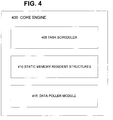
- the core engine 400 comprises individual software components that work together in a modular fashion to read device inventories, user access control systems and control network-monitoring systems.
- a task scheduler 405 is cron-run, as opposed to running as a formal daemon, in order to extend its flexibility for the many roles that it performs.
- the functionality can be turned on and off via command line switches, allowing the core engine to be run in several different modes simultaneously. Therefore, one instance of the core engine 400 can be run in auto-discovery mode, detecting devices on the network, while another auto-configures tools and controls communication of the polled data flow into the back-end database. Still another instance might be correlating data between the device inventory and the actual current network topology.
- the core engine uses static memory resident structures 410 to hold all device and service configuration information.
- static memory consumes more memory during runtime, the memory structures are protected from other systemic processes, and therefore will not be corrupted if the system runs low on memory.
- static memory allows the program a faster runtime when compared to a dynamic memory based system, which consumes several CPU cycles while allocating, reallocating, and cleaning memory.
- this is not meant as a limitation.
- the tasks of the core engine may be implemented in software and hardware in numerous ways without departing from the scope of the present invention which is defined in the appended claims.
- the core engine comprises a data poller module (DPM) 415 for polling devices in the field via SNMP or by executing command-line interface commands on the devices being monitored to obtain updated configuration information.
- DPM data poller module
- the core engine receives updated configuration data from DPM and compares the actual status of devices in the field against the last known configuration of the devices stored on the DIDB (not shown). This comparison is done by running the DPM against a specified device and comparing the results of the poll with all of the values of the memory resident structures.
- the DPM 415 uses the SNMP and Telnet data acquisition methods, as well as Open Shortest Path First (OSPF) autodiscovery, to perform aggressive SNMP community string testing for devices with which it cannot communicate. This analysis is performed to ensure the data integrity of the DIDB and the synchronization of the NMS applications. Discrepancies found between the actual router field configuration and the database values are flagged by the modification of the status column value to "changed". An exception report in the form of an email is then generated and forwarded to a designated change control address, informing both network operations center (NOC) and support system personnel of the device change. An SNMP trap, indicating the change, is also generated and sent to the NMS server.
- NOC network operations center
- NOC personnel are able to compare this event with any planned tickets and act accordingly. Additionally, when the elements of a specified device are found to have differences, the core engine discerns both which device interface has changed and the old and new SNMP index values for the interface. This analysis helps preserve archived network monitoring data that is listed using a set of primary keys (SNMP Interface Index, Interface IP address, and Type/Slot).
- the core engine 400 uses the configuration values stored in the DIDB structure to configure the NMS tools (applications) to reflect the changes.
- the SNMP traps and email exception reports contain all relevant information regarding the elements changed and the before and after values, in order to accomplish accurate change management for each modified device. If the SNMP index values have changed and the device is flagged for monitoring via the monitoring column of the structure, an automatic reconfiguration event for all NMS tools is initiated to reflect the given change. This mechanism ensures that changes found in the network are communicated to applications across the network and flagged as exceptions for further analysis.
- an autocontroller the components of an autocontroller are illustrated according to an exemplary embodiment of the present invention.
- the autocontroller illustrated in Figure 5 is illustrative of functions performed by an autocontroller according to the present invention, but the invention is not limited to the functions illustrated.
- the autocontroller manages the applications running on an application server. The functions of a particular autocontroller are therefore specific to the applications that it manages.
- the autocontroller application is coded in a modular fashion thereby simplifying the addition of new tools (applications).
- the code comprises software modules that the autocontroller loads into memory, creating a simple process for modifying the autocontroller behavior towards each network management application and customizing the autocontroller to function with network management applications of various vendors.
- Each application under the core engine control uses the same autocontroller module, with each tool type and option selectable via command line switches.
- the autocontroller application is generic to any specific network management application.
- Each application governed by the autocontroller is unique and requires customized code for to permit the autocontroller to perform its assigned management tasks.
- a module permits the autocontroller to stop, started, restart, manipulate, and direct an application. Because the command structure differs among applications, a unique module customized to an application is used. The process is run under cron control, with safeguards to block multiple instances, allowing better application control and a customizable run frequency.
- One of the primary functions of the autocontroller is to update files for network management applications in the field with files created by the core engine. After being generated by the core engine, the freshly created configuration files, binary files, modules and the like are transferred to the appropriate application server. In an exemplary embodiment of the present invention, this transfer is accomplished via file transfer protocol (FTP) or secure protocol (SCP) and the transferred filed is stored in an incoming directory 505 to await processing.
- FTP file transfer protocol
- SCP secure protocol
- Each configuration file follows a strict naming convention that also allows for a custom (unique) component.
- the autocontroller is designed to accept program binary updates, data collection/analyzer files, and shell command files.
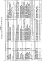
- FIG. 6 illustrates the core engine/autocontroller transfer file formats as used in an exemplary embodiment according to the present invention.
- the network applications are components of Netcool® SuitTM produced by MicroMuse Inc., but this is not meant as a limitation.
- each transfer file name is broken down into four or five dot-notated words. For example: acfile. ⁇ ID>. ⁇ unique piece>. ⁇ TAG>.[DSM]
- the first word, acfile identifies the file as one that the autocontroller should process.
- the ⁇ ID> represents the instance number in the meta-data configuration file.
- the ⁇ TAG> is one of the filename and tags listed in the table above.
- the optional [DSM] defines the DSM to which this file pertains, and is used by the event reporting module and applications running on the NMS poller servers.
- Each application governed by the autocontroller is unique and requires customized code for such management tasks as being stopped, started, restarted, manipulated, or directed.
- the autocontroller has an application code module 515 dedicated to each application that it supports.
- Each application is tied to a command line trigger so that individual applications can be activated or not activated, as desired, depending upon the autocontroller location and purpose.
- each file listed in the incoming directory has its filename parsed to determine whether it is a core engine transfer file. Once the filename is parsed and identified, specific action is taken depending upon the file being transferred to the autocontroller.
- the ⁇ ID> field ties each transfer file back to a specific application instance in the meta-data configuration file, determining the application type and location to which the file applies, as well as other details.
- the ⁇ TAG> field defines the type of transfer file being sent in, and thus determines the course of action to be taken regarding the contents of the file.
- the files are renamed to the application standard, moved into position, and a restart of the application is scheduled.
- the file represents shell commands to be executed (one command per line).
- the [DSM] field event reporting module, defines the role of the configuration file being propagated.
- DSM No. 1 is primary and DSM No. 2 is the backup file for use by a remote data center (RDC) in the event the primary data control center is unable to perform its tasks.
- RDC remote data center
- the file is compressed and archived in a storage directory 510. If the autocontroller fails to successfully process a transfer file, it issues an alarm notification and the file remains in the incoming directory so that processing may be reattempted the next time the autocontroller launches. This allows transfer files to accumulate in the incoming directory 505, and to be processed at another time; to ensure that no change is lost should the autocontroller fail to operate for any reason.
- the shell command processor 545 of the autocontroller of this exemplary embodiment fulfills several requirements. First, it is used to activate, deactivate, and restart applications, when necessary, from a centralized location. Using this feature the core engine can direct and coordinate the redundancy features of each autocontroller instance in the field.
- the shell command processor 545 also serves as a mechanism for data collection of non-SNMP data, such as traceroute, by listing processes running on a server and gathering statistical information about server performance that is not otherwise available through a network management tool. It can also be used in a utilitarian role to globally execute changes on all autocontroller servers (or some grouping there of). This capability grants the core engine and its autocontroller enormous flexibility and data collection capability.
- the shell commands executed using this feature run from the same account as the autocontroller, which is never the root user. Each command is run individually and has its output directed to a log file that the autocontroller will later analyze and return to the core engine as a result file. This logging allows the core engine to confirm that each shell command executed properly, and provides an easy mechanism for gathering data from the field servers.
- the format of the shell command input file consists of each shell command to be executed on a single line of ASCII text.
- a result analyzer module 520 of the autocontroller parses output files and the results from selected applications and perform actions based upon that analysis.
- parsing comprises processing a text output file or configuration file following the execution of shell commands, reconfiguration commands, and log files by the autocontroller.
- the result analyzer module 520 runs after all incoming transfer files are processed and all commands and reconfigurations are complete. When the results of this analysis require that the data be returned to the core engine, output files with the appropriate naming convention are created and moved to the outgoing directory to be transferred.
- the result analyzer module 520 will return the raw output of each command executed in an easy to parse format that the core engine can process.
- the shell commands processing files are sent to the autocontroller from the core engine, where they are executed one command at a time and the results placed in a specially formatted output file. In this manner, any desired shell commands can be run on the autocontroller server at will, providing the core engine and its autocontroller instances with great control and flexibility over their operating environment.
- a result analyzer module 520 is used with a DSM (distributed status monitor) 550 to analyze the results of device reconfigurations.
- DSM distributed status monitor
- the results of that reconfiguration are placed in an ASCII log file 555.
- a successful reconfiguration will result in a configuration file that a DSM will use to SNMP poll that device.
- These device configuration files contain valuable information about the interfaces that reside on the device, as well as a listing of each object identifier (OID) polled for the device.
- the result analyzer module 520 parses both of these files to determine if the reconfiguration was successful, and if so, to mine the device configuration file for critical data. This data is placed in a specially formatted output file in the outgoing directory that is picked up by the transfer file process and returned to the core engine.
- a file return module 560 is used to send result files and other data from an instance of the autocontroller to the core engine servers.
- the file return module 560 uses both FTP and SCP as the actual transfer mechanism, both of which are selectable using command line options.
- the file return module 560 utilizes a user-selected outgoing directory that it will scan for files to be transferred. This process does not depend on a particular file naming convention, but rather, will transfer any file located in the outgoing directory to the core engine.
- This generic operation of the file return module 560 allows the autocontroller and other applications (if required) to perform a myriad of different tasks and simply place their return output in the outgoing directory, as each task is completed. For security purposes, the autocontroller will only return files to the core engine, and not to other user-defined locations.
- the file return module 560 is one of the last functions performed by the autocontroller during runtime operation.
- each autocontroller supports a redundancy module 565.
- the purpose of the redundancy module is to detect failures and handle application failover.
- the autocontroller instances will start and stop a backup application instance, locally store critical SNMP data, and literally shut themselves down or reactivate themselves depending upon their status and the status of an assigned buddy autocontroller.
- the autocontroller has an internal ping module 570 that allows it to perform pings against the core engine core and other autocontroller servers.
- the autocontroller also has an integration module 575 that allows it to make SNMP, I CMP, trace-route, and Web queries using a standardized XML-like messaging library.
- the autocontroller redundancy module 565 initiates a series of tasks to reestablish communication. All autocontroller instances involved will send alarm traps and e-mails, and log the event.
- the autocontroller will launch one or more instances of the event reporting module 580 in order to capture critical SNMP data in local files, which can then be transferred and uploaded to the NDB later.
- the core engine core When the core engine core becomes reachable again, it commands the autocontroller to resume normal communication with the core.
- the backup event reporting module instances are shut down and their locally held data files are moved into the outgoing directory for transport. Once in the outgoing directory the return file module 560 will handle the actual transport back to the core engine core.
- the autocontroller redundancy module if connectivity to a buddy autocontroller is lost the autocontroller redundancy module initiates tasks to reestablish communication with the buddy autocontroller.
- the following cause/effect scenarios are accounted for in this embodiment of the autocontroller redundancy module:
- the core engine utilizes two configuration files to perform all of its necessary operations: Meta-Configuration and object identifier (OID) configuration. These files contain specific instructions for the management of network management applications.
- the core engine and the autocontroller use the same Meta-configuration file, which allows the core and field elements to remain completely synchronized.
- the configuration file is read in when the autocontroller boots. This file is broken down into three main sections using a single simplified attribute/value pair table that is designed for direct integration with the DIDB database. In this manner, the DIDB control the activities of each field autocontroller instance.
- the Meta-configuration file contains three fields, an integer ID field and attribute/value pair fields. The ID number determines the application instance to which each attributes/value pair belongs. The first section designates the core engine core, the second the autocontroller, and the remaining sections are for each application instance.
- the network applications are components of Netcool® SuitTM produced by MicroMuse Inc. and the OpenView suit of NMS products produced by Hewlett-Packard Company, but this is not meant as a limitation.
- Each application instance has a unique ID number for it's each attribute/value pairs.
- the schema architecture of the Meta-configuration files used in this embodiment for the core engine and the autocontroller instances was chosen for several reasons. The use of a simple attribute/value pair format makes the integration with databases clean and easy to change and manipulate. The core engine and the autocontroller instances connect to the DIDB to poll the configuration file directly.
- the autocontroller makes a local backup copy of the meta-data configuration file so that in the event the database becomes unreachable, the autocontroller is can continue to function using their last good read from DIDB.
- each variable is incorporated into its name, using a logical naming convention. If more than one word comprises a variable, each word in the variable is capitalized (example: PollingSite).
- the meta-data design is completely extensible out to an infinite number of application instances without requiring structural changes. This feature of the configuration file is especially useful in network management systems with large network device inventories.
- the meta-data format further accommodates the creation and propagation of the same network management tool's configuration file to several locations. For example, multiple instances of an application may unique instances defined in the configuration file. Because both the core engine and each autocontroller use the same configuration file, the core engine core and the inventory of autocontrollers are always synchronized with one another.
- the autocontroller attempts to connect to the DIDB and read its meta-configuration file using scripts. If this succeeds, a fresh local backup of the meta-configuration is saved to disk. If it fails, the autocontroller issues an alarm and falls back to the last known good copy of the meta-configuration file stored on disk. Once the meta-configuration file is read, it is stored in memory structures that mimic the file structure.
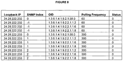
- the object identifier configuration file provides a mechanism for specifying how SNMP OIDs are gathered.
- Each device and device interface can have a custom list of OIDs that are polled and expected back via a report of that data.
- the autocontroller uses this configuration data to build the event reporting module configuration files, which specify the OID data required from each device in the field.
- the OID configuration file comprises:
- the OID configuration file is similar in structure to a base configuration file, with the addition of two fields - 'Polling Interval' and 'Status'.
- the format thus allows each device and device interface known to the DIDB to have OIDs defined at custom intervals for retrieval, storage in the NDB, and reporting.
- Another similarity to the base meta-configuration file is that the OID configuration file is prepared from a table in the DIDB schema, and the same OID configuration file is used by all autocontroller instances.
- the present invention has been described in the context of a network manage system in which the data to be synchronized comprises configuration data.
- the "network" is a distributed financial system and the data to be synchronized financial variables that are used by various applications of the financial system.
- the central database receives reports of changes in financial variables from information gathering applications across a financial network.
- the core engine monitors the central data structure, determines if a financial variable has changed within the network, then populates the changes to all network applications. In this way, the financial network is "synchronized” as to the variables that are deemed important to the functioning of the financial network.
- the present invention can be applied to any system in which disparate components benefit from synchronization (such as billing systems and weather systems) without departing from the scope of the present invention as defined by the appended claims.
Landscapes
- Engineering & Computer Science (AREA)
- Computer Networks & Wireless Communication (AREA)
- Signal Processing (AREA)
- Health & Medical Sciences (AREA)
- Computing Systems (AREA)
- General Health & Medical Sciences (AREA)
- Medical Informatics (AREA)
- Automation & Control Theory (AREA)
- Computer And Data Communications (AREA)
- Telephonic Communication Services (AREA)
- Data Exchanges In Wide-Area Networks (AREA)
Claims (16)
- System zur Verwaltung von Änderungen, enthaltend:mehrere aus der Gruppe der mit einem Netzwerk verbundenen konfigurierbaren Netzwerkgeräte (235, 240, 245) und Anwendungen ausgewählte Netzwerkverwaltungsobjekte,wobei jedes Netzwerkverwaltungsobjekt mit Netzwerkverwaltungsobjekt-Konfigurationsinformationen verknüpft ist;mehrere Netzwerk-Anwendungsserver (225),wobei auf jedem Netzwerk-Anwendungsserver eine oder mehrere Anwendungen residieren und jeder der mehreren Netzwerk-Anwendungsserver dazu ausgebildet ist,über das Netzwerk mit mindestens einem Netzwerkverwaltungsobjekt zu kommunizieren;einen Datenspeicher (200), wobei der Datenspeicher mit denNetzwerkverwaltungsobjekten verknüpfte letzte bekannte Konfigurationsinformationen enthält;einen mit dem Netzwerk verbundenen Core Engine (215), wobei der Core Engine dazu ausgebildet ist:die mehreren Netzwerkverwaltungsobjekte nach aktuellen Konfigurationsinformationen für jedes der mehreren Netzwerkverwaltungsobjekte abzufragen;von jedem der mehreren Netzwerkverwaltungsobjekte die aktuellen Konfigurationsinformationen zu empfangen; undfür jedes der mehreren Netzwerkverwaltungsobjekte zu ermitteln, ob die aktuellen Netzwerkverwaltungsobjekt-Konfigurationsinformationen von den im Datenspeicher gespeicherten letzten bekannten Netzwerkverwaltungsobjekt-Konfigurationsinformationen abweichen;falls die aktuellen Netzwerkverwaltungsobjekt-Konfigurationsinformationen von den letzten bekannten Netzwerkverwaltungsobjekt-Konfigurationsinformationen abweichen, die vom Netzwerkverwaltungsobjekt erhaltenen aktuellen Netzwerkverwaltungsobjekt-Konfigurationsinformationen zu verarbeiten, um eine neue Netzwerkverwaltungsobjekt-Konfigurationsdatei zu erhalten; unddie neue Netzwerkverwaltungsobjekt-Konfigurationsdatei an einen Controller-Server (220) zu senden, der mit mindestens einem der mehreren Anwendungsserver verbunden ist, auf dem mindestens eine Anwendung residiert,wobei das System auch den genannten Controller-Server beinhaltet, der dazu ausgebildet ist, die eine oder die mehreren Anwendungen auf jedem Netzwerk-Anwendungsserver mit der neuen Netzwerkverwaltungsobjekt-Konfigurationsdatei zu konfigurieren.
- Das System nach Anspruch 1, wobei das Netzwerkverwaltungsobjekt ein konfigurierbares Gerät umfasst.
- Das System nach Anspruch 2, wobei das Gerät aus der Gruppe bestehend aus einem Switch, einem Modem und einem Server ausgewählt ist.
- Das System nach Anspruch 1, wobei das Netzwerkverwaltungsobjekt eine konfigurierbare Anwendung umfasst.
- Das System nach Anspruch 4, wobei die konfigurierbare Anwendung aus der Gruppe bestehend aus einem Poller, einer Reporting-Engine, einem Netzwerkportal und einem Zugangskontrollserver ausgewählt ist.
- Das System nach Anspruch 1, wobei der Core Engine weiter dazu ausgebildet ist, den Datenspeicher mit den aktuellen Netzwerkverwaltungsobjekt-Konfigurationsinformationen des Netzwerkverwaltungsobjekts zu aktualisieren.
- Das System nach Anspruch 1, wobei das Netzwerkverwaltungsobjekt keine letzten bekannten Konfigurationsinformationen aufweist.
- Das System nach Anspruch 1, wobei der Controller-Server dazu ausgebildet ist:eine Anwendung aus einer oder mehreren Anwendungen, die auf jedem Netzwerk-Anwendungsserver residieren, zur Aktualisierung zu ermitteln;die neue Netzwerkverwaltungsobjekt-Konfigurationsdatei zu empfangen;die neue Netzwerkverwaltungsobjekt-Konfigurationsdatei in ein von der ermittelten Anwendung akzeptiertes Format zu konvertieren;eine Konfiguration der ermittelten Anwendung mit einer geeigneten konvertierten Konfiguration zu aktualisieren;die jeweilige Anwendung zu beenden; unddie jeweilige Anwendung neu zu starten.
- Das System nach Anspruch 1, wobei der Controller-Server zudem mit einem Buddy-Anwendungsserver verbunden ist, wobei der Controller-Server dazu ausgebildet ist:die Konnektivität zwischen dem einen der mehreren Netzwerk-Anwendungsserver und dem Buddy-Netzwerk-Anwendungsserver zu überwachen;falls die Konnektivität zwischen dem einen der mehreren Netzwerk-Anwendungsserver und dem Buddy-Netzwerk-Anwendungsserver unterbrochen ist, auf dem einen der mehreren Netzwerk-Anwendungsserver eine Backup-Instanz einer vom Buddy-Netzwerk-Anwendungsserver ausgeführten Anwendung zu starten;die Backup-Instanz der Anwendung auf dem einen der mehreren Netzwerk-Anwendungsserver auszuführen, um die Aufgaben des Buddy-Netzwerk-Anwendungsservers auszuführen;die Konnektivität zwischen dem einen der mehreren Netzwerk-Anwendungsserver und dem Buddy-Netzwerk-Anwendungsserver zu überwachen; undfalls die Konnektivität zwischen dem einen der mehreren Netzwerk-Anwendungsserver und dem Buddy-Netzwerk-Anwendungsserver wiederhergestellt ist, die Backup-Instanz der Anwendung auf dem einen der mehreren Netzwerk-Anwendungsserver zu schliessen.
- Das System nach Anspruch 1, wobei das Netzwerk aus der Gruppe bestehend aus einem hybriden Glasfasemetz, einem kabelgebundenen Netzwerk und einem drahtlosen Netzwerk ausgewählt ist.
- Das System nach Anspruch 1, wobei das Netzwerk das Internet ist.
- Das System nach Anspruch 1, wobei das Netzwerk ein Intranet ist.
- Verfahren zur Verwaltung von Änderungen in einem Netzwerk, enthaltend:das Speichern (345) der letzten bekannten Konfigurationsinformationen mehrerer aus der Gruppe der mit einem Netzwerk verbundenen konfigurierbaren Netzwerkgeräte und Anwendungen ausgewählter Netzwerkverwaltungsobjekte in einer zentralen Datenbank; das Abfragen (312) der mehreren Netzwerkverwaltungsobjekte nach aktuellen Konfigurationsinformationen für jedes der mehreren Netzwerkverwaltungsobjekte durch einen Core Engine;das Empfangen (314) der aktuellen Konfigurationsinformationen von jedem der mehreren Netzwerkverwaltungsobjekte durch den Core Engine; unddas Ermitteln (316) für jedes der mehreren Netzwerkverwaltungsobjekte mittels des Core Engines, ob aktuelle Netzwerkverwaltungsobjekt-Konfigurationsinformationen von in der zentralen Datenbank gespeicherten letzten bekannten Netzwerkverwaltungsobjekt-Konfigurationsinformationen abweichen;falls die aktuellen Netzwerkverwaltungsobjekt-Konfigurationsinformationen von den letzten bekannten Netzwerkverwaltungsobjekt-Konfigurationsinformationen abweichen (320), das Verarbeiten (325, 330) der vom Netzwerkverwaltungsobjekt erhaltenen Netzwerkverwaltungsobjekt-Konfigurationsinformationen mittels des Core Engines, um eine neue Netzwerkverwaltungsobjekt-Konfigurationsdatei zu erhalten; unddas Senden (335) der neuen Netzwerkverwaltungsobjekt-Konfigurationsdatei mittels des Core Engines an einen Controller-Server, der mit mindestens einem der mehreren Anwendungsserver verbunden ist, auf dem mindestens eine Anwendung residiert,wobei der Controller-Server die eine oder die mehreren Anwendungen auf jedem Netzwerk-Anwendungsserver mit der neuen Netzwerkverwaltungsobjekt-Konfigurationsdatei konfiguriert (340).
- Das Verfahren nach Anspruch 13, wobei das Netzwerk aus der Gruppe bestehend aus einem hybriden Glasfasernetz, einem kabelgebundenen Netzwerk und einem drahtlosen Netzwerk ausgewählt ist.
- Das Verfahren nach Anspruch 13, wobei das Netzwerk das Internet ist.
- Das Verfahren nach Anspruch 13, wobei das Netzwerk ein Intranet ist.
Applications Claiming Priority (5)
| Application Number | Priority Date | Filing Date | Title |
|---|---|---|---|
| US335272 | 1999-06-17 | ||
| US38751702P | 2002-06-07 | 2002-06-07 | |
| US387517P | 2002-06-07 | ||
| US10/335,272 US20030229686A1 (en) | 2002-06-07 | 2002-12-31 | System and method for synchronizing the configuration of distributed network management applications |
| PCT/US2003/017911 WO2003104930A2 (en) | 2002-06-07 | 2003-06-06 | System and method for synchronizing the configuration of distributed network management applications |
Publications (3)
| Publication Number | Publication Date |
|---|---|
| EP1556777A2 EP1556777A2 (de) | 2005-07-27 |
| EP1556777A4 EP1556777A4 (de) | 2010-09-01 |
| EP1556777B1 true EP1556777B1 (de) | 2018-05-30 |
Family
ID=29715011
Family Applications (1)
| Application Number | Title | Priority Date | Filing Date |
|---|---|---|---|
| EP03734453.8A Expired - Lifetime EP1556777B1 (de) | 2002-06-07 | 2003-06-06 | System und verfahren zur synchronisierung der konfiguration verteilter netzwerkverwaltungsanwendungen |
Country Status (5)
| Country | Link |
|---|---|
| US (1) | US20030229686A1 (de) |
| EP (1) | EP1556777B1 (de) |
| AU (1) | AU2003238932A1 (de) |
| CA (1) | CA2488044C (de) |
| WO (1) | WO2003104930A2 (de) |
Families Citing this family (41)
| Publication number | Priority date | Publication date | Assignee | Title |
|---|---|---|---|---|
| US7409714B2 (en) * | 2001-06-13 | 2008-08-05 | Mcafee, Inc. | Virtual intrusion detection system and method of using same |
| US8549114B2 (en) | 2002-06-12 | 2013-10-01 | Bladelogic, Inc. | Method and system for model-based heterogeneous server configuration management |
| CN1283063C (zh) * | 2003-05-20 | 2006-11-01 | 华为技术有限公司 | 通信设备中配置数据的方法及装置 |
| GB0312489D0 (en) * | 2003-05-30 | 2003-07-09 | Nokia Corp | Terminal setting change notification |
| US20050044192A1 (en) * | 2003-07-28 | 2005-02-24 | Applin John R. | Web site management system with link management functionality |
| US20050114240A1 (en) * | 2003-11-26 | 2005-05-26 | Brett Watson-Luke | Bidirectional interfaces for configuring OSS components |
| CN100349408C (zh) * | 2004-02-12 | 2007-11-14 | 华为技术有限公司 | 实现网管系统和网元设备配置数据实时同步的方法 |
| US8065408B2 (en) * | 2004-06-30 | 2011-11-22 | Nokia, Inc. | Method and system for dynamic device address management |
| US7610374B2 (en) * | 2004-08-27 | 2009-10-27 | Ricoh Company Ltd. | Method of initializing a data processing object associated with a communication protocol used to extract status information related to a monitored device |
| US20060053418A1 (en) | 2004-09-02 | 2006-03-09 | Packetfront Sweden Ab | Network management system configuring |
| CN100373864C (zh) * | 2004-11-01 | 2008-03-05 | 华为技术有限公司 | 通信系统配置数据库的管理系统和管理方法 |
| US20060123016A1 (en) * | 2004-12-02 | 2006-06-08 | International Business Machines Corporation | Metadata driven method and apparatus to configure heterogenous distributed systems |
| CN100359862C (zh) * | 2004-12-06 | 2008-01-02 | 华为技术有限公司 | 一种网元管理系统之间传递网管配置信息的方法 |
| US7610610B2 (en) | 2005-01-10 | 2009-10-27 | Mcafee, Inc. | Integrated firewall, IPS, and virus scanner system and method |
| US7581000B2 (en) * | 2005-01-11 | 2009-08-25 | Ricoh Company, Ltd. | Monitoring device having a memory containing data representing access information configured to be used by multiple implementations of protocol access functions to extract information from networked devices |
| US7734574B2 (en) * | 2005-02-17 | 2010-06-08 | International Business Machines Corporation | Intelligent system health indicator |
| EP1703667A1 (de) * | 2005-03-15 | 2006-09-20 | Siemens Aktiengesellschaft | Netzwerkmanagement unter Verwendung eines Master-Replica-Verfahrens |
| JP4405933B2 (ja) * | 2005-03-18 | 2010-01-27 | キヤノン株式会社 | 制御装置、通信制御方法、通信制御プログラム、及び記憶媒体 |
| US7870246B1 (en) | 2005-08-30 | 2011-01-11 | Mcafee, Inc. | System, method, and computer program product for platform-independent port discovery |
| US8775460B2 (en) | 2005-12-08 | 2014-07-08 | International Business Machines Corporation | Managing changes to computer system |
| US7917904B2 (en) * | 2006-01-06 | 2011-03-29 | Microsoft Corporation | Automated analysis tasks of complex computer system |
| US7904899B2 (en) * | 2006-06-20 | 2011-03-08 | Intuit Inc. | Third-party customization of a configuration file |
| US8406140B2 (en) * | 2006-08-22 | 2013-03-26 | Wal-Mart Stores, Inc. | Network device inventory system |
| CN100461701C (zh) * | 2006-08-24 | 2009-02-11 | 华为技术有限公司 | 网管和网元的网络资源一致性的校验方法及其系统 |
| US7590550B2 (en) * | 2006-09-08 | 2009-09-15 | American Well Inc. | Connecting consumers with service providers |
| JP4565429B2 (ja) * | 2007-12-18 | 2010-10-20 | コニカミノルタビジネステクノロジーズ株式会社 | 管理システム及び管理方法並びに制御プログラム |
| US20090217382A1 (en) * | 2008-02-25 | 2009-08-27 | Alcatel-Lucent | Method and procedure to automatically detect router security configuration changes and optionally apply corrections based on a target configuration |
| US7984199B2 (en) * | 2008-03-05 | 2011-07-19 | Fisher-Rosemount Systems, Inc. | Configuration of field devices on a network |
| US8422400B2 (en) * | 2009-10-30 | 2013-04-16 | Cisco Technology, Inc. | Method and apparatus for discovering devices in a network |
| US20120290707A1 (en) * | 2011-05-10 | 2012-11-15 | Monolith Technology Services, Inc. | System and method for unified polling of networked devices and services |
| US9407506B2 (en) | 2011-09-12 | 2016-08-02 | Microsoft Technology Licensing, Llc | Multi-entity management |
| CN103036694A (zh) * | 2011-09-29 | 2013-04-10 | 中兴通讯股份有限公司 | 分布式网络中的业务配置方法和装置 |
| JP5966765B2 (ja) * | 2012-08-22 | 2016-08-10 | 富士通株式会社 | 情報処理システム、中継装置、情報処理プログラム、及び情報処理方法 |
| WO2014056558A1 (en) * | 2012-10-12 | 2014-04-17 | Technische Universität Dortmund | Computer implemented method for hybrid simulation of power distribution network and associated communication network for real time applications |
| US8972334B2 (en) * | 2012-12-21 | 2015-03-03 | International Business Machines Corporation | Transparent data service suitable for modifying data storage capabilities in applications |
| GB2518254B (en) | 2013-09-13 | 2020-12-16 | Vodafone Ip Licensing Ltd | Communicating with a machine to machine device |
| US20150088957A1 (en) * | 2013-09-25 | 2015-03-26 | Sony Corporation | System and methods for managing applications in multiple devices |
| EP2903209B1 (de) * | 2014-01-30 | 2018-11-14 | Siemens Aktiengesellschaft | Verfahren zur Aktualisierung von Nachrichtenfilterregeln einer Netzzugangskontrolleinheit eines industriellen Kommunikationsnetzes, Adressverwaltungseinheit und Konvertereinheit |
| US10735269B2 (en) * | 2018-08-31 | 2020-08-04 | QOS Networking, Inc. | Apparatus and method for dynamic discovery and visual mapping of computer networks |
| US11467862B2 (en) * | 2019-07-22 | 2022-10-11 | Vmware, Inc. | Application change notifications based on application logs |
| US12166636B1 (en) | 2023-09-20 | 2024-12-10 | Insight Direct Usa, Inc. | Network protocol-based interrogation for network device characterization |
Citations (4)
| Publication number | Priority date | Publication date | Assignee | Title |
|---|---|---|---|---|
| EP1039685A2 (de) * | 1998-10-29 | 2000-09-27 | Nortel Networks Limited | Gesichertes Netzwerk mit LDAP (lightweight directory access protocol) |
| EP1107108A1 (de) * | 1999-12-09 | 2001-06-13 | Hewlett-Packard Company, A Delaware Corporation | System und Verfahren zum Verwalten der Konfiguration von Datenverarbeitungsvorrichtungen in einem hierarchischen Netz |
| US6292472B1 (en) * | 1998-10-22 | 2001-09-18 | Alcatel | Reduced polling in an SNMPv1-managed network |
| WO2002039351A2 (en) * | 2000-11-01 | 2002-05-16 | Seebeyond Technology Corporation | Sytems and methods for providing centralized management of heterogeneous distributed enterprise application integration objects |
Family Cites Families (16)
| Publication number | Priority date | Publication date | Assignee | Title |
|---|---|---|---|---|
| US5835911A (en) * | 1994-02-08 | 1998-11-10 | Fujitsu Limited | Software distribution and maintenance system and method |
| US5758083A (en) * | 1995-10-30 | 1998-05-26 | Sun Microsystems, Inc. | Method and system for sharing information between network managers |
| GB2308778B (en) * | 1995-12-28 | 1998-06-10 | Nokia Telecommunications Oy | Telecommunications network management system |
| US5909568A (en) * | 1996-09-03 | 1999-06-01 | Apple Computer, Inc. | Process and apparatus for transferring data between different file formats |
| US5785083A (en) * | 1997-03-12 | 1998-07-28 | Rheem Manufacturing Company | Tubular refrigerant check valve with snap-together internal valve cage structure |
| US6363411B1 (en) * | 1998-08-05 | 2002-03-26 | Mci Worldcom, Inc. | Intelligent network |
| US5999978A (en) * | 1997-10-31 | 1999-12-07 | Sun Microsystems, Inc. | Distributed system and method for controlling access to network resources and event notifications |
| US6295558B1 (en) * | 1998-08-21 | 2001-09-25 | Hewlett-Packard Company | Automatic status polling failover or devices in a distributed network management hierarchy |
| US6128656A (en) * | 1998-09-10 | 2000-10-03 | Cisco Technology, Inc. | System for updating selected part of configuration information stored in a memory of a network element depending on status of received state variable |
| US6405219B2 (en) * | 1999-06-22 | 2002-06-11 | F5 Networks, Inc. | Method and system for automatically updating the version of a set of files stored on content servers |
| US6345239B1 (en) * | 1999-08-31 | 2002-02-05 | Accenture Llp | Remote demonstration of business capabilities in an e-commerce environment |
| US20020057018A1 (en) | 2000-05-20 | 2002-05-16 | Equipe Communications Corporation | Network device power distribution scheme |
| US7130870B1 (en) * | 2000-05-20 | 2006-10-31 | Ciena Corporation | Method for upgrading embedded configuration databases |
| FI20002402A7 (fi) * | 2000-11-01 | 2002-05-02 | Nokia Corp | Konfiguroinnin hallinta hajautetussa ympäristössä |
| US20030009552A1 (en) * | 2001-06-29 | 2003-01-09 | International Business Machines Corporation | Method and system for network management with topology system providing historical topological views |
| US7082464B2 (en) * | 2001-07-06 | 2006-07-25 | Juniper Networks, Inc. | Network management system |
-
2002
- 2002-12-31 US US10/335,272 patent/US20030229686A1/en not_active Abandoned
-
2003
- 2003-06-06 AU AU2003238932A patent/AU2003238932A1/en not_active Abandoned
- 2003-06-06 CA CA2488044A patent/CA2488044C/en not_active Expired - Lifetime
- 2003-06-06 EP EP03734453.8A patent/EP1556777B1/de not_active Expired - Lifetime
- 2003-06-06 WO PCT/US2003/017911 patent/WO2003104930A2/en not_active Ceased
Patent Citations (4)
| Publication number | Priority date | Publication date | Assignee | Title |
|---|---|---|---|---|
| US6292472B1 (en) * | 1998-10-22 | 2001-09-18 | Alcatel | Reduced polling in an SNMPv1-managed network |
| EP1039685A2 (de) * | 1998-10-29 | 2000-09-27 | Nortel Networks Limited | Gesichertes Netzwerk mit LDAP (lightweight directory access protocol) |
| EP1107108A1 (de) * | 1999-12-09 | 2001-06-13 | Hewlett-Packard Company, A Delaware Corporation | System und Verfahren zum Verwalten der Konfiguration von Datenverarbeitungsvorrichtungen in einem hierarchischen Netz |
| WO2002039351A2 (en) * | 2000-11-01 | 2002-05-16 | Seebeyond Technology Corporation | Sytems and methods for providing centralized management of heterogeneous distributed enterprise application integration objects |
Also Published As
| Publication number | Publication date |
|---|---|
| CA2488044A1 (en) | 2003-12-18 |
| WO2003104930A3 (en) | 2005-05-19 |
| AU2003238932A8 (en) | 2003-12-22 |
| CA2488044C (en) | 2012-04-03 |
| WO2003104930A2 (en) | 2003-12-18 |
| AU2003238932A1 (en) | 2003-12-22 |
| EP1556777A2 (de) | 2005-07-27 |
| US20030229686A1 (en) | 2003-12-11 |
| EP1556777A4 (de) | 2010-09-01 |
Similar Documents
| Publication | Publication Date | Title |
|---|---|---|
| EP1556777B1 (de) | System und verfahren zur synchronisierung der konfiguration verteilter netzwerkverwaltungsanwendungen | |
| US7523184B2 (en) | System and method for synchronizing the configuration of distributed network management applications | |
| EP1790130B1 (de) | Agiles system zur verwaltung von informationstechnologieinfrastrukturen | |
| US6983321B2 (en) | System and method of enterprise systems and business impact management | |
| EP1267518B1 (de) | Verfahren und Vorrichtung zum Verwalten von mehreren Netzwerkgeräten | |
| US20080101419A1 (en) | Methods and apparatus for network configuration baselining and restoration | |
| US20030009552A1 (en) | Method and system for network management with topology system providing historical topological views | |
| US20160179850A1 (en) | Methods and Apparatus for Providing Adaptive Private Network Database Schema Migration and Management Processes | |
| US20080098454A1 (en) | Network Management Appliance | |
| US7305485B2 (en) | Method and system for network management with per-endpoint adaptive data communication based on application life cycle | |
| US7680907B2 (en) | Method and system for identifying and conducting inventory of computer assets on a network | |
| US20030041139A1 (en) | Event management for a remote network policy management system | |
| US20040205689A1 (en) | System and method for managing a component-based system | |
| CN102521099A (zh) | 一种进程监控方法及进程监控系统 | |
| US20020165934A1 (en) | Displaying a subset of network nodes based on discovered attributes | |
| CA2434241A1 (en) | System and method for configuration, management and monitoring of network resources | |
| US20020112040A1 (en) | Method and system for network management with per-endpoint monitoring based on application life cycle | |
| CN117880132B (zh) | 一种基于ib网络的集群拓扑测试方法和装置 | |
| Webb et al. | Implementing the Emulab-PlanetLab Portal: Experience and Lessons Learned. | |
| EP4580142A1 (de) | Audit-log zur verwaltung von netzwerkvorrichtungen | |
| WO2000042513A1 (en) | Network management system | |
| CN121967187A (zh) | 设备管理方法、装置、设备及可读存储介质 | |
| CN120371375A (zh) | 基于Ansible的信息系统的监控运维系统、方法、设备及介质 | |
| Bohdanowicz et al. | The problematic of distributed systems supervision-an example: Genesys | |
| WO2005106694A2 (en) | Methods and systems for history analysis and predictive change management for access paths in networks |
Legal Events
| Date | Code | Title | Description |
|---|---|---|---|
| PUAI | Public reference made under article 153(3) epc to a published international application that has entered the european phase |
Free format text: ORIGINAL CODE: 0009012 |
|
| AK | Designated contracting states |
Kind code of ref document: A2 Designated state(s): AT BE BG CH CY CZ DE DK EE ES FI FR GB GR HU IE IT LI LU MC NL PT RO SE SI SK TR |
|
| AX | Request for extension of the european patent |
Extension state: AL LT LV MK |
|
| DAX | Request for extension of the european patent (deleted) | ||
| 17P | Request for examination filed |
Effective date: 20051121 |
|
| RBV | Designated contracting states (corrected) |
Designated state(s): AT BE BG CH CY CZ DE DK EE ES FI FR GB GR HU IE IT LI LU MC NL PT RO SE SI SK TR |
|
| A4 | Supplementary search report drawn up and despatched |
Effective date: 20100802 |
|
| RIC1 | Information provided on ipc code assigned before grant |
Ipc: H04L 12/24 20060101ALI20100727BHEP Ipc: H04L 12/26 20060101ALI20100727BHEP Ipc: G06F 15/173 20060101AFI20050608BHEP |
|
| 17Q | First examination report despatched |
Effective date: 20110317 |
|
| RAP1 | Party data changed (applicant data changed or rights of an application transferred) |
Owner name: TIME WARNER CABLE, A DIVISION OF TIME WARNER ENTER |
|
| GRAP | Despatch of communication of intention to grant a patent |
Free format text: ORIGINAL CODE: EPIDOSNIGR1 |
|
| INTG | Intention to grant announced |
Effective date: 20170608 |
|
| GRAJ | Information related to disapproval of communication of intention to grant by the applicant or resumption of examination proceedings by the epo deleted |
Free format text: ORIGINAL CODE: EPIDOSDIGR1 |
|
| GRAP | Despatch of communication of intention to grant a patent |
Free format text: ORIGINAL CODE: EPIDOSNIGR1 |
|
| INTC | Intention to grant announced (deleted) | ||
| INTG | Intention to grant announced |
Effective date: 20171213 |
|
| GRAS | Grant fee paid |
Free format text: ORIGINAL CODE: EPIDOSNIGR3 |
|
| GRAA | (expected) grant |
Free format text: ORIGINAL CODE: 0009210 |
|
| RAP1 | Party data changed (applicant data changed or rights of an application transferred) |
Owner name: TIME WARNER CABLE, INC. |
|
| RAP1 | Party data changed (applicant data changed or rights of an application transferred) |
Owner name: TIME WARNER CABLE ENTERPRISES LLC |
|
| AK | Designated contracting states |
Kind code of ref document: B1 Designated state(s): AT BE BG CH CY CZ DE DK EE ES FI FR GB GR HU IE IT LI LU MC NL PT RO SE SI SK TR |
|
| REG | Reference to a national code |
Ref country code: GB Ref legal event code: FG4D |
|
| REG | Reference to a national code |
Ref country code: CH Ref legal event code: EP |
|
| REG | Reference to a national code |
Ref country code: AT Ref legal event code: REF Ref document number: 1004331 Country of ref document: AT Kind code of ref document: T Effective date: 20180615 |
|
| REG | Reference to a national code |
Ref country code: FR Ref legal event code: PLFP Year of fee payment: 16 |
|
| REG | Reference to a national code |
Ref country code: IE Ref legal event code: FG4D |
|
| REG | Reference to a national code |
Ref country code: DE Ref legal event code: R096 Ref document number: 60351223 Country of ref document: DE |
|
| REG | Reference to a national code |
Ref country code: NL Ref legal event code: MP Effective date: 20180530 |
|
| PG25 | Lapsed in a contracting state [announced via postgrant information from national office to epo] |
Ref country code: ES Free format text: LAPSE BECAUSE OF FAILURE TO SUBMIT A TRANSLATION OF THE DESCRIPTION OR TO PAY THE FEE WITHIN THE PRESCRIBED TIME-LIMIT Effective date: 20180530 Ref country code: CY Free format text: LAPSE BECAUSE OF FAILURE TO SUBMIT A TRANSLATION OF THE DESCRIPTION OR TO PAY THE FEE WITHIN THE PRESCRIBED TIME-LIMIT Effective date: 20180530 Ref country code: BG Free format text: LAPSE BECAUSE OF FAILURE TO SUBMIT A TRANSLATION OF THE DESCRIPTION OR TO PAY THE FEE WITHIN THE PRESCRIBED TIME-LIMIT Effective date: 20180830 Ref country code: FI Free format text: LAPSE BECAUSE OF FAILURE TO SUBMIT A TRANSLATION OF THE DESCRIPTION OR TO PAY THE FEE WITHIN THE PRESCRIBED TIME-LIMIT Effective date: 20180530 Ref country code: SE Free format text: LAPSE BECAUSE OF FAILURE TO SUBMIT A TRANSLATION OF THE DESCRIPTION OR TO PAY THE FEE WITHIN THE PRESCRIBED TIME-LIMIT Effective date: 20180530 |
|
| PG25 | Lapsed in a contracting state [announced via postgrant information from national office to epo] |
Ref country code: GR Free format text: LAPSE BECAUSE OF FAILURE TO SUBMIT A TRANSLATION OF THE DESCRIPTION OR TO PAY THE FEE WITHIN THE PRESCRIBED TIME-LIMIT Effective date: 20180831 |
|
| REG | Reference to a national code |
Ref country code: AT Ref legal event code: MK05 Ref document number: 1004331 Country of ref document: AT Kind code of ref document: T Effective date: 20180530 |
|
| PG25 | Lapsed in a contracting state [announced via postgrant information from national office to epo] |
Ref country code: NL Free format text: LAPSE BECAUSE OF FAILURE TO SUBMIT A TRANSLATION OF THE DESCRIPTION OR TO PAY THE FEE WITHIN THE PRESCRIBED TIME-LIMIT Effective date: 20180530 |
|
| PG25 | Lapsed in a contracting state [announced via postgrant information from national office to epo] |
Ref country code: RO Free format text: LAPSE BECAUSE OF FAILURE TO SUBMIT A TRANSLATION OF THE DESCRIPTION OR TO PAY THE FEE WITHIN THE PRESCRIBED TIME-LIMIT Effective date: 20180530 Ref country code: SK Free format text: LAPSE BECAUSE OF FAILURE TO SUBMIT A TRANSLATION OF THE DESCRIPTION OR TO PAY THE FEE WITHIN THE PRESCRIBED TIME-LIMIT Effective date: 20180530 Ref country code: CZ Free format text: LAPSE BECAUSE OF FAILURE TO SUBMIT A TRANSLATION OF THE DESCRIPTION OR TO PAY THE FEE WITHIN THE PRESCRIBED TIME-LIMIT Effective date: 20180530 Ref country code: DK Free format text: LAPSE BECAUSE OF FAILURE TO SUBMIT A TRANSLATION OF THE DESCRIPTION OR TO PAY THE FEE WITHIN THE PRESCRIBED TIME-LIMIT Effective date: 20180530 Ref country code: AT Free format text: LAPSE BECAUSE OF FAILURE TO SUBMIT A TRANSLATION OF THE DESCRIPTION OR TO PAY THE FEE WITHIN THE PRESCRIBED TIME-LIMIT Effective date: 20180530 Ref country code: EE Free format text: LAPSE BECAUSE OF FAILURE TO SUBMIT A TRANSLATION OF THE DESCRIPTION OR TO PAY THE FEE WITHIN THE PRESCRIBED TIME-LIMIT Effective date: 20180530 |
|
| REG | Reference to a national code |
Ref country code: CH Ref legal event code: PL |
|
| PG25 | Lapsed in a contracting state [announced via postgrant information from national office to epo] |
Ref country code: IT Free format text: LAPSE BECAUSE OF FAILURE TO SUBMIT A TRANSLATION OF THE DESCRIPTION OR TO PAY THE FEE WITHIN THE PRESCRIBED TIME-LIMIT Effective date: 20180530 |
|
| REG | Reference to a national code |
Ref country code: DE Ref legal event code: R097 Ref document number: 60351223 Country of ref document: DE |
|
| REG | Reference to a national code |
Ref country code: BE Ref legal event code: MM Effective date: 20180630 |
|
| REG | Reference to a national code |
Ref country code: IE Ref legal event code: MM4A |
|
| PG25 | Lapsed in a contracting state [announced via postgrant information from national office to epo] |
Ref country code: MC Free format text: LAPSE BECAUSE OF FAILURE TO SUBMIT A TRANSLATION OF THE DESCRIPTION OR TO PAY THE FEE WITHIN THE PRESCRIBED TIME-LIMIT Effective date: 20180530 Ref country code: LU Free format text: LAPSE BECAUSE OF NON-PAYMENT OF DUE FEES Effective date: 20180606 |
|
| PLBE | No opposition filed within time limit |
Free format text: ORIGINAL CODE: 0009261 |
|
| STAA | Information on the status of an ep patent application or granted ep patent |
Free format text: STATUS: NO OPPOSITION FILED WITHIN TIME LIMIT |
|
| PG25 | Lapsed in a contracting state [announced via postgrant information from national office to epo] |
Ref country code: LI Free format text: LAPSE BECAUSE OF NON-PAYMENT OF DUE FEES Effective date: 20180630 Ref country code: CH Free format text: LAPSE BECAUSE OF NON-PAYMENT OF DUE FEES Effective date: 20180630 Ref country code: IE Free format text: LAPSE BECAUSE OF NON-PAYMENT OF DUE FEES Effective date: 20180606 |
|
| 26N | No opposition filed |
Effective date: 20190301 |
|
| PG25 | Lapsed in a contracting state [announced via postgrant information from national office to epo] |
Ref country code: SI Free format text: LAPSE BECAUSE OF FAILURE TO SUBMIT A TRANSLATION OF THE DESCRIPTION OR TO PAY THE FEE WITHIN THE PRESCRIBED TIME-LIMIT Effective date: 20180530 Ref country code: BE Free format text: LAPSE BECAUSE OF NON-PAYMENT OF DUE FEES Effective date: 20180630 |
|
| PG25 | Lapsed in a contracting state [announced via postgrant information from national office to epo] |
Ref country code: TR Free format text: LAPSE BECAUSE OF FAILURE TO SUBMIT A TRANSLATION OF THE DESCRIPTION OR TO PAY THE FEE WITHIN THE PRESCRIBED TIME-LIMIT Effective date: 20180530 |
|
| PG25 | Lapsed in a contracting state [announced via postgrant information from national office to epo] |
Ref country code: HU Free format text: LAPSE BECAUSE OF FAILURE TO SUBMIT A TRANSLATION OF THE DESCRIPTION OR TO PAY THE FEE WITHIN THE PRESCRIBED TIME-LIMIT; INVALID AB INITIO Effective date: 20030606 Ref country code: PT Free format text: LAPSE BECAUSE OF FAILURE TO SUBMIT A TRANSLATION OF THE DESCRIPTION OR TO PAY THE FEE WITHIN THE PRESCRIBED TIME-LIMIT Effective date: 20180530 |
|
| PGFP | Annual fee paid to national office [announced via postgrant information from national office to epo] |
Ref country code: GB Payment date: 20220519 Year of fee payment: 20 Ref country code: FR Payment date: 20220519 Year of fee payment: 20 Ref country code: DE Payment date: 20220518 Year of fee payment: 20 |
|
| REG | Reference to a national code |
Ref country code: DE Ref legal event code: R071 Ref document number: 60351223 Country of ref document: DE |
|
| REG | Reference to a national code |
Ref country code: GB Ref legal event code: PE20 Expiry date: 20230605 |
|
| P01 | Opt-out of the competence of the unified patent court (upc) registered |
Effective date: 20230526 |
|
| PG25 | Lapsed in a contracting state [announced via postgrant information from national office to epo] |
Ref country code: GB Free format text: LAPSE BECAUSE OF EXPIRATION OF PROTECTION Effective date: 20230605 |