EP1556869B1 - Verfahren, verwendung und einrichtung bezüglich mantelröhren für kernbrennstoff und einer brennstoffbaugruppe für einen druckwasserkernreaktor - Google Patents
Verfahren, verwendung und einrichtung bezüglich mantelröhren für kernbrennstoff und einer brennstoffbaugruppe für einen druckwasserkernreaktor Download PDFInfo
- Publication number
- EP1556869B1 EP1556869B1 EP03809908A EP03809908A EP1556869B1 EP 1556869 B1 EP1556869 B1 EP 1556869B1 EP 03809908 A EP03809908 A EP 03809908A EP 03809908 A EP03809908 A EP 03809908A EP 1556869 B1 EP1556869 B1 EP 1556869B1
- Authority
- EP
- European Patent Office
- Prior art keywords
- tube
- alloy
- weight percent
- nuclear
- cladding
- Prior art date
- Legal status (The legal status is an assumption and is not a legal conclusion. Google has not performed a legal analysis and makes no representation as to the accuracy of the status listed.)
- Revoked
Links
- 238000005253 cladding Methods 0.000 title claims abstract description 69
- 239000000446 fuel Substances 0.000 title claims abstract description 37
- 238000000034 method Methods 0.000 title claims abstract description 37
- XLYOFNOQVPJJNP-UHFFFAOYSA-N water Substances O XLYOFNOQVPJJNP-UHFFFAOYSA-N 0.000 title claims abstract description 27
- 239000003758 nuclear fuel Substances 0.000 title claims abstract description 12
- 229910045601 alloy Inorganic materials 0.000 claims abstract description 39
- 239000000956 alloy Substances 0.000 claims abstract description 39
- 238000005275 alloying Methods 0.000 claims abstract description 13
- 238000001953 recrystallisation Methods 0.000 claims abstract description 12
- 229910052726 zirconium Inorganic materials 0.000 claims abstract description 12
- 229910052758 niobium Inorganic materials 0.000 claims abstract description 9
- 238000010438 heat treatment Methods 0.000 claims description 10
- 230000015572 biosynthetic process Effects 0.000 claims description 6
- 229910001093 Zr alloy Inorganic materials 0.000 claims description 5
- 239000012535 impurity Substances 0.000 claims description 5
- 125000006850 spacer group Chemical group 0.000 claims description 3
- 238000005096 rolling process Methods 0.000 claims 1
- 239000010955 niobium Substances 0.000 abstract description 14
- QCWXUUIWCKQGHC-UHFFFAOYSA-N Zirconium Chemical compound [Zr] QCWXUUIWCKQGHC-UHFFFAOYSA-N 0.000 abstract description 5
- GUCVJGMIXFAOAE-UHFFFAOYSA-N niobium atom Chemical group [Nb] GUCVJGMIXFAOAE-UHFFFAOYSA-N 0.000 abstract description 5
- 238000004519 manufacturing process Methods 0.000 description 11
- 150000004678 hydrides Chemical class 0.000 description 9
- 238000005755 formation reaction Methods 0.000 description 5
- 239000000463 material Substances 0.000 description 5
- 230000005855 radiation Effects 0.000 description 5
- 239000000126 substance Substances 0.000 description 5
- 239000000203 mixture Substances 0.000 description 3
- 238000005482 strain hardening Methods 0.000 description 3
- 238000000137 annealing Methods 0.000 description 2
- 230000000694 effects Effects 0.000 description 2
- 239000007791 liquid phase Substances 0.000 description 2
- 239000002245 particle Substances 0.000 description 2
- 239000008188 pellet Substances 0.000 description 2
- 239000011241 protective layer Substances 0.000 description 2
- 238000011282 treatment Methods 0.000 description 2
- UFHFLCQGNIYNRP-UHFFFAOYSA-N Hydrogen Chemical compound [H][H] UFHFLCQGNIYNRP-UHFFFAOYSA-N 0.000 description 1
- 229910001257 Nb alloy Inorganic materials 0.000 description 1
- 229910052770 Uranium Inorganic materials 0.000 description 1
- 230000000712 assembly Effects 0.000 description 1
- 238000000429 assembly Methods 0.000 description 1
- 238000009835 boiling Methods 0.000 description 1
- 238000010276 construction Methods 0.000 description 1
- 230000007797 corrosion Effects 0.000 description 1
- 238000005260 corrosion Methods 0.000 description 1
- 230000002349 favourable effect Effects 0.000 description 1
- 229910052739 hydrogen Inorganic materials 0.000 description 1
- 239000001257 hydrogen Substances 0.000 description 1
- 230000003993 interaction Effects 0.000 description 1
- 239000010410 layer Substances 0.000 description 1
- GFUGMBIZUXZOAF-UHFFFAOYSA-N niobium zirconium Chemical compound [Zr].[Nb] GFUGMBIZUXZOAF-UHFFFAOYSA-N 0.000 description 1
- 239000012071 phase Substances 0.000 description 1
- JFALSRSLKYAFGM-UHFFFAOYSA-N uranium(0) Chemical compound [U] JFALSRSLKYAFGM-UHFFFAOYSA-N 0.000 description 1
Images
Classifications
-
- C—CHEMISTRY; METALLURGY
- C22—METALLURGY; FERROUS OR NON-FERROUS ALLOYS; TREATMENT OF ALLOYS OR NON-FERROUS METALS
- C22C—ALLOYS
- C22C16/00—Alloys based on zirconium
-
- C—CHEMISTRY; METALLURGY
- C22—METALLURGY; FERROUS OR NON-FERROUS ALLOYS; TREATMENT OF ALLOYS OR NON-FERROUS METALS
- C22F—CHANGING THE PHYSICAL STRUCTURE OF NON-FERROUS METALS AND NON-FERROUS ALLOYS
- C22F1/00—Changing the physical structure of non-ferrous metals or alloys by heat treatment or by hot or cold working
- C22F1/16—Changing the physical structure of non-ferrous metals or alloys by heat treatment or by hot or cold working of other metals or alloys based thereon
- C22F1/18—High-melting or refractory metals or alloys based thereon
- C22F1/186—High-melting or refractory metals or alloys based thereon of zirconium or alloys based thereon
-
- G—PHYSICS
- G21—NUCLEAR PHYSICS; NUCLEAR ENGINEERING
- G21C—NUCLEAR REACTORS
- G21C3/00—Reactor fuel elements and their assemblies; Selection of substances for use as reactor fuel elements
- G21C3/02—Fuel elements
- G21C3/04—Constructional details
- G21C3/06—Casings; Jackets
- G21C3/07—Casings; Jackets characterised by their material, e.g. alloys
-
- Y—GENERAL TAGGING OF NEW TECHNOLOGICAL DEVELOPMENTS; GENERAL TAGGING OF CROSS-SECTIONAL TECHNOLOGIES SPANNING OVER SEVERAL SECTIONS OF THE IPC; TECHNICAL SUBJECTS COVERED BY FORMER USPC CROSS-REFERENCE ART COLLECTIONS [XRACs] AND DIGESTS
- Y02—TECHNOLOGIES OR APPLICATIONS FOR MITIGATION OR ADAPTATION AGAINST CLIMATE CHANGE
- Y02E—REDUCTION OF GREENHOUSE GAS [GHG] EMISSIONS, RELATED TO ENERGY GENERATION, TRANSMISSION OR DISTRIBUTION
- Y02E30/00—Energy generation of nuclear origin
- Y02E30/30—Nuclear fission reactors
-
- Y—GENERAL TAGGING OF NEW TECHNOLOGICAL DEVELOPMENTS; GENERAL TAGGING OF CROSS-SECTIONAL TECHNOLOGIES SPANNING OVER SEVERAL SECTIONS OF THE IPC; TECHNICAL SUBJECTS COVERED BY FORMER USPC CROSS-REFERENCE ART COLLECTIONS [XRACs] AND DIGESTS
- Y10—TECHNICAL SUBJECTS COVERED BY FORMER USPC
- Y10T—TECHNICAL SUBJECTS COVERED BY FORMER US CLASSIFICATION
- Y10T29/00—Metal working
- Y10T29/49—Method of mechanical manufacture
- Y10T29/4935—Heat exchanger or boiler making
- Y10T29/49391—Tube making or reforming
Definitions
- the present invention concerns cladding tubes for nuclear fuel for a nuclear pressure water reactor. More precisely, the invention concerns such cladding tubes which are formed of a Zr-based alloy which contains Nb.
- the invention concerns, inter alia, a method. According to the method, a tube is formed which at least principally consists of a cylindrical tube component of a Zr-based alloy, where the alloying element, except for Zr, which has the highest content in the alloy is Nb, wherein the Nb content in weight percent is between 0.5 and 2.4.
- the invention also concerns a cladding tube as such, a use of a cladding tube and a fuel assembly for a nuclear pressure water reactor comprising such a cladding tube.
- EP-A-0 198 570 discloses a process for manufacturing thin-walled tubing from a zirconium-niobium alloy containing from 1 to 2.5% by weight niobium as homogeneously dispersed finely divided particles, the process comprising:
- a cladding tube When a cladding tube is used in a nuclear reactor, it contains nuclear fuel, usually in the form of pellets comprising enriched uranium, usually in the form of UO 2 .
- the cladding tube with its content thus constitutes a fuel rod. Because of the very particular environment in which cladding tubes are used, different requirements must be fulfilled.
- BWR boiling water reactors
- PWR pressure water reactors
- the fuel rods are cooled mainly by water that is in a liquid phase under a high pressure.
- the pressure is lower and the water which cools the fuel rods is evaporated such that the fuel rods are surrounded both by water in a liquid phase and in a steam phase.
- the fuel assemblies have different construction in a BWR and a PWR.
- the fuel rods in a fuel assembly extend all the way between a top plate and a bottom plate which keep the fuel assembly together.
- the fuel rods are usually held in position with the help of spacers and do not reach all the way to the top plate and the bottom plate.
- a fuel rod which is used in a nuclear reactor is exposed to high temperatures and pressures. Over time thereby creep phenomena occur. Such a creep should as far as possible be avoided since it can have negative effects. For example, a creep of the fuel rods may have as a consequence that they will press against the fuel pellets which are located therein.
- the neutron radiation to which a fuel rod is exposed when it is used may also have as a consequence that the fuel rod tends to grow with time. Also such a growth caused by neutron radiation may have undesired effects. It should therefore be avoided that the cladding tube grows to a larger extent. Modern fuel rods which are produced in suitable zirconium alloys and which undergo special heat treatments during the production often have a relatively low tendency to grow when they are exposed to neutron radiation. The tendency to grow may be reduced, inter alia in that the cladding tube during the production undergoes a final recrystallization anneal.
- the cladding tube can obtain suitable properties concerning for example hardness and ductility.
- cladding tubes In the environment where the cladding tubes are used they may be subject to different corrosive attacks. These attacks may come from the outside or from the inside. The attacks from the inside often have their basis in an influence from the nuclear fuel material that is located there, so-called pellet-cladding interaction (PCI). If a crack is formed through the cladding tube (a so-called primary damage), water may penetrate in through the crack and spread along the inside of the tube. This may lead to new corrosive attacks from the inside of the tube, so-called secondary damages. A cladding tube of zirconium or zirconium-based alloys may also react with hydrogen such that hydrides are formed in the cladding tube.
- PCI pellet-cladding interaction
- hydrides may be formed from the inside of the tube, particularly if a crack has been formed such that water has penetrated into the tube. These hydrides make the tube more fragile and the probability for the formation of cracks increases. Particularly hydrides that extend in a radial direction through the tube constitute an increased risk for crack formation. Such radial hydrides may therefore speed up possible secondary damages and crack formations.
- Cladding tubes produced of a Zr-based alloy which contains Nb has appeared to have good properties in many respects.
- suitable alloying contents for example such as described in the above mentioned US-A-5 648 995
- a suitable choice of parameters of production a cladding tube can be obtained which has good chemical, mechanical and metallurgical properties. It has however become clear that also for tubes of this kind there is a risk of damages.
- An object of the present invention is therefore to achieve a method of producing a cladding tube, of a Zr-based alloy which includes between 0.5 weight percent and 2.4 weight percent Nb and which has an improved resistance against damages than prior cladding tubes of this kind of alloys.
- a cladding tube produced according to this method has appeared to have a good resistance against damages caused by PCI at the same time as the risk for the formation of radial hydrides is low. Thereby, the risk for cracks is reduced.
- the cladding tube has at the same time also a high ductility, a low creep rate and a low tendency to growth caused by neutron radiation. Further objects and advantages of the invention will become clear from the following.
- the final anneal is normally the last heat treatment step in the method of production. Possibly, a certain after treatment of the cladding tube may be carried out, but such an after treatment should be such that the structure which is obtained through the final anneal is not essentially destroyed.
- the cladding tube consists only of said tube component. There are thus no further layers.
- the composition of the outer surface and the inner surface of the tube may however-differ from the composition in the inner of the tube, for example due to the substances that the tube has come into contact with.
- the tube may for example be oxidised through the fact that it has been kept in an environment of air.
- the tube comprises one or more further protective layers on its inside or its outside.
- the tube thus consists of several components. It is however always the case that said tube component constitutes the main component of the tube, for example that this tube component constitutes more than 60% of the thickness of the tube. As has been pointed out above, it is however preferred that the whole thickness of the tube is made up of said tube component.
- the final anneal is carried out such that the degree of recrystallization in the tube component is higher than 40%, for example between 60% and 90% and lower than 95 % . It has become clear that such degrees of recrystallization are particularly suitable for achieving the described advantages.
- the temperature and the time that are needed in order to achieve such a degree of recrystallization depend on the contents of the alloying elements.
- the temperature for the final anneal is preferably lower than 550°C, for example between 400°C and 540°C, and often most preferred between 450°C and 500°C.
- the final anneal may suitably be carried out during 1h to 6h, preferably during 1 to 3 hours.
- the method comprises, before said final anneal, the following steps:
- Such a method of production is suitable in order to obtain favourable properties of the cladding tube. It should be noted that the method of production of course may comprise further steps (for example further heat treatments or cold rolls) in addition to those mentioned above.
- the Nb-content in said alloy is between 0.8 weight percent and 1.2 weight percent.
- No alloying element, except for Zr and Nb, in said alloy has a content which exceeds 0.3 weight percent, and preferably not above 0.2 weight percent.
- the alloy may suitably contain between 800ppm and 1700ppm O. Such a selection of the content of O leads to the fact that the cladding tube has good creep properties.
- the alloy contains between 50ppm and 600ppm Fe.
- the Fe-content may for example be lower than 250ppm. It should be noted that these low Fe-contents are only preferred embodiments of the invention. According to another embodiment, also a higher Fe-content may be permitted.
- the alloy may also contain a certain amount of S, for example between 20ppm S and 600ppm S, or between 100ppm S and 600ppm S. Such an amount of S can improve the corrosion resistance of the alloy and the creep properties.
- said alloy contains, in addition to Zr, 0.8 weight percent to 1.2 weight percent Nb, 50ppm to 600ppm Fe, 800ppm to 1700ppm O, less than 250ppm C, less than 150ppm Si, less than 1000ppm S and in addition to that only impurities of a content which does not exceed that which is normally accepted in Zr or Zr alloys for applications in nuclear reactors.
- the invention also concerns a use as defined claim 10.
- a cladding tube produced according to the method according to any of the preceding embodiments is used in a fuel assembly for a nuclear pressure water reactor.
- the above described advantages with such a cladding tube are achieved.
- the invention also concerns a cladding tube as defined in claim 11 , suitable to contain nuclear fuel for a nuclear pressure water reactor.
- Such a cladding tube can be produced according to the above-described method.
- Advantageous embodiments for example concerning included alloying elements and alloying contents, are clear from the examples above in connection with the method according to the invention. With these embodiments of the cladding tube, the above-described advantages are achieved.
- the invention also concerns a fuel assembly for a nuclear pressure water reactior as defined in claim 16.
- the fuel assembly comprises a plurality of cladding tubes according to the invention filled with nuclear fuel suitable for such cladding tubes for a nuclear pressure water reactor.
- Fig 1 shows schematically a fuel assembly, known per se, for a PWR.
- the fuel assembly comprises a top plate 4 and a bottom plate 5. Between the top plate 4 and the bottom plate 5 a plurality of guide tubes 3 for control rods extend. Furthermore, the fuel assembly comprises a plurality of cladding tubes 1. These cladding tubes 1 thus contain a nuclear fuel material and are thereby called fuel rods. In this kind of fuel assembly for PWR, the fuel rods do not reach all the way to the top plate 4 and to the bottom plate 5. The fuel rods are kept in position in the fuel assembly with the help of spacers 2.
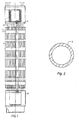
- Fig 2 shows schematically a cross-section through a cladding tube according to the invention.
- the cross section shows the cladding tube strongly enlarged.
- the cladding- tube is of a dimension and of a length which are suitable for use in a PWR.
- the cladding tube comprises a cylindrical tube component 1.
- the cylindrical tube component 1 constitutes the whole cladding tube. This is the preferred embodiment.
- this tube component 1 has one or more protective layers on its inside or outside.
- the tube component 1 consists of a Zr-based alloy. This means that the tube component to the largest extent, always more than 95%, consists of Zr.
- the tube component 1 contains the following alloying elements: 1% Nb, 1200ppm O, 200ppm Fe, less than 200ppm C, less than 150ppm Si, less than 1000ppm S and in addition to that only impurities of a content which does not exceed that which is normally accepted in Zr or Zr alloys for applications in nuclear reactors.
- the cladding tube has been finally annealed such that the tube component 1 has a structure such that it is partly recrystallized but not completely recrystallized.
- the degree of recrystallization may for example be about 85%.
- the invention also concerns a method of producing a cladding tube for nuclear fuel for a nuclear pressure water reactor.
- the method according to the invention may be carried out in the following manner.
- a bar of for example the above-mentioned alloy is formed. This bar is heated to between 900°C and 1300°C and is thereafter quenched, preferably in water.
- a billet is extruded from the bar after heating to between 500°C and 900°C.
- the billet is cold rolled to a tube in at least two steps (for example in three steps), with heat treatments between them at between 550°C and 650°C.
- the tube is final annealed at a temperature and during a time such that the tube component is partly recrystallized but not completely recrystallized.
- the final anneal may for example be carried out at a temperature of about 490°C during about two hours.
- the final anneal is carried out such that a suitable degree of recrystallization is obtained in the tube. This degree of recrystallization is higher than 40% and lower than 95%.
- a degree of recrystallization of for example between 60% and 90% can be suitable, for example a degree of recrystallization of about 85%.
- a cladding tube produced according to the method may suitably be used in a fuel assembly in a nuclear PWR.
Landscapes
- Engineering & Computer Science (AREA)
- Chemical & Material Sciences (AREA)
- Physics & Mathematics (AREA)
- Metallurgy (AREA)
- Organic Chemistry (AREA)
- Materials Engineering (AREA)
- Mechanical Engineering (AREA)
- Crystallography & Structural Chemistry (AREA)
- Thermal Sciences (AREA)
- Plasma & Fusion (AREA)
- General Engineering & Computer Science (AREA)
- High Energy & Nuclear Physics (AREA)
- Monitoring And Testing Of Nuclear Reactors (AREA)
- Heat Treatment Of Nonferrous Metals Or Alloys (AREA)
- Heat Treatment Of Articles (AREA)
- Jet Pumps And Other Pumps (AREA)
Claims (17)
- Verfahren zur Herstellung einer Mantelröhre für Kernbrennstoff für einen Druckwasserkernreaktor, wobei das Verfahren die folgenden Schritte aufweist:Ausbildung einer Röhre, die zumindest hauptsächlich aus einem zylindrischen Röhrenteil (1) aus einer Legierung auf der Basis von Zr besteht, wobei das Legierungselement außer Zr, das den höchsten Gehalt in der Legierung aufweist, Nb ist, wobei der Nb-Gehalt in Gewichtsprozent zwischen 0,5 und 2,4 beträgt und wobei kein Legierungselement außer Zr und Nb in der besagten Legierung einen Gehalt aufweist, der über 0,3 Gewichtsprozent liegt, dadurch gekennzeichnet, dass nach der Ausbildung der Mantelröhre gemäß dem oben genannten Schritt und nach möglichen Walzschritten, zwischen denen Wärmebehandlungen durchgeführt werden, die Mantelröhre schließlich bei einer Temperatur und während eines Zeitraums derart geglüht wird, dass das besagte Röhrenteil (1) teilweise, aber nicht vollständig rekristallisiert wird, wobei das besagte abschließende Glühen derart durchgeführt wird, dass der Grad der Rekristallisation in dem besagten Röhrenteil (1) über 40% und unter 95% beträgt.
- Verfahren nach Anspruch 1, wobei das abschließende Glühen bei einer Temperatur unter 550°C durchgeführt wird.
- Verfahren nach einem der vorhergehenden Ansprüche, wobei das abschließende Glühen bei einer Temperatur zwischen 400°C und 540°C durchgeführt wird.
- Verfahren nach einem der vorhergehenden Ansprüche, wobei das abschließende Glühen während eines Zeitraums von 1h bis 6h durchgeführt wird.
- Verfahren nach einem der vorhergehenden Ansprüche, wobei das Verfahren vor dem besagten abschließenden Glühen die folgenden Schritte aufweist:ein Barren aus der besagten Legierung auf der Basis von Zr wird ausgebildet;dieser Barren wird auf eine Temperatur zwischen 900°C und 1300°C erhitzt und danach, vorzugsweise in Wasser, abgeschreckt;ein Knüppel wird aus dem Barren nach einer Erhitzung auf eine Temperatur zwischen 500°C und 900°C extrudiert;der Knüppel wird in zumindest zwei Schritten, zwischen denen Wärmebehandlungen bei einer Temperatur zwischen 550°C und 650°C durchgeführt werden, zu einer Röhre kaltgewalzt.
- Verfahren nach einem der vorhergehenden Ansprüche, wobei der Nb-Gehalt in der besagten Legierung zwischen 0,8 Gewichtsprozent und 1,2 Gewichtsprozent beträgt.
- Verfahren nach einem der vorhergehenden Ansprüche, wobei die besagte Legierung zwischen 800ppm und 600ppm O enthält.
- Verfahren nach einem der vorhergehenden Ansprüche, wobei die besagte Legierung zwischen 50ppm und 600ppm Fe enthält.
- Verfahren nach einem der vorhergehenden Ansprüche, wobei die besagte Legierung neben Zr 0,8 Gewichtsprozent bis 1,2 Gewichtsprozent Nb, 50ppm bis 600ppm Fe, 800ppm bis 1700ppm O, weniger als 250ppm C, weniger als 150ppm Si, weniger als 1000ppm S und daneben ausschließlich Verunreinigungen eines Gehalts, der nicht über dem liegt, was in Zr oder Zr-Legierungen zur Anwendung in Kernreaktoren üblicherweise akzeptiert wird, enthält.
- Verwendung einer Mantelröhre, die gemäß dem Verfahren nach einem der vorhergehenden Ansprüche hergestellt wird, in einer Brennstoffbaugruppe für einen Druckwasserkernreaktor.
- Mantelröhre für Kernbrennstoff für einen Druckwasserkernreaktor, wobei die Mantelröhre zumindest hauptsächlich aus einem zylindrischen Röhrenteil (1) aus einer Legierung auf der Basis von Zr besteht, wobei das Legierungselement, das außer Zr den höchsten Gehalt in der Legierung aufweist, Nb ist, wobei der Nb-Gehalt in Gewichtsprozent zwischen 0,5 und 2,4 liegt und wobei kein Legierungselement außer Zr und Nb in der besagten Legierung einen Gehalt aufweist, der über 0,3 Gewichtsprozent liegt, wobei das besagte Röhrenteil (1) derart abschließend geglüht wurde, dass es eine Struktur derart aufweist, dass es teilweise, aber nicht vollständig rekristallisiert wird, und wobei der Grad der Rekristallisation in dem besagten Röhrenteil (1) über 40% und unter 95% beträgt.
- Mantelföhre nach Anspruch 11, wobei der Nb-Gehalt in der besagten Legierung zwischen 0,8 Gewichtsprozent und 1,2 Gewichtsprozent beträgt.
- Mantelröhre nach einem der Ansprüche 11-12, wobei die besagte Legierung zwischen 800ppm und 1700ppm O enthält.
- Mantelröhre nach einem der Ansprüche 11-13, wobei die besagte Legierung zwischen 50ppm und 600ppm Fe enthält.
- Mantelröhre nach einem der Ansprüche 11-14, wobei die besagte Legierung neben Zr 0,8 Gewichtsprozent bis 1,2 Gewichtsprozent Nb, 50ppm bis 600ppm Fe, 800ppm bis 1700ppm O, weniger als 250ppm C, weniger als 150ppm Si, weniger als 1000ppm S und daneben ausschließlich Verunreinigungen eines Gehalts, der nicht über dem liegt, was in Zr oder Zr-Legierungen zur Anwendung in Kernreaktoren üblicherweise akzeptiert wird, enthält.
- Kernstoffbaugruppe für einen Druckwasserkernreaktor, aufweisend:eine Vielzahl von Mantelröhren (1) nach einem der Ansprüche 11-15, die mit Kernbrennstoff gefüllt sind, der für derartige Mantelröhren (1) für einen Druckwasserkernreaktor geeignet ist.
- Kernstoffbaugruppe nach Anspruch 16, aufweisend:eine obere Platte (4),eine untere Platte (5),eine Vielzahl von Führungsröhren (3) für Regelstäbe, wobei sich die Führungsröhren zwischen der oberen Platte (4) und der unteren Platte (5) erstrecken, undeine Vielzahl von Abstandshaltern (2), die zur Aufrechterhaltung der besagten Mantelröhren (1) in der Kernstoffbaugruppe in Position und in geeigneten Abständen voneinander angeordnet sind.
Applications Claiming Priority (3)
| Application Number | Priority Date | Filing Date | Title |
|---|---|---|---|
| SE0203198 | 2002-10-30 | ||
| SE0203198A SE525808C2 (sv) | 2002-10-30 | 2002-10-30 | Förfarande, användning och anordning avseende kapslingrör för kärnbränsle samt en bränslepatron för en nukleär tryckvattenreaktor |
| PCT/SE2003/001685 WO2004040587A1 (en) | 2002-10-30 | 2003-10-30 | Method, use and device concerning cladding tubes for nuclear fuel and a fuel assembly for a nuclear pressure water reactor |
Publications (2)
| Publication Number | Publication Date |
|---|---|
| EP1556869A1 EP1556869A1 (de) | 2005-07-27 |
| EP1556869B1 true EP1556869B1 (de) | 2011-12-07 |
Family
ID=20289408
Family Applications (1)
| Application Number | Title | Priority Date | Filing Date |
|---|---|---|---|
| EP03809908A Revoked EP1556869B1 (de) | 2002-10-30 | 2003-10-30 | Verfahren, verwendung und einrichtung bezüglich mantelröhren für kernbrennstoff und einer brennstoffbaugruppe für einen druckwasserkernreaktor |
Country Status (7)
| Country | Link |
|---|---|
| US (2) | US7473329B2 (de) |
| EP (1) | EP1556869B1 (de) |
| AT (1) | ATE536619T1 (de) |
| AU (1) | AU2003276790A1 (de) |
| ES (1) | ES2377645T3 (de) |
| SE (1) | SE525808C2 (de) |
| WO (1) | WO2004040587A1 (de) |
Families Citing this family (10)
| Publication number | Priority date | Publication date | Assignee | Title |
|---|---|---|---|---|
| SE0203048D0 (sv) * | 2002-10-15 | 2002-10-15 | Digityper Ab | Portable device |
| US10221475B2 (en) | 2004-03-23 | 2019-03-05 | Westinghouse Electric Company Llc | Zirconium alloys with improved corrosion/creep resistance |
| US9284629B2 (en) | 2004-03-23 | 2016-03-15 | Westinghouse Electric Company Llc | Zirconium alloys with improved corrosion/creep resistance due to final heat treatments |
| US8721810B2 (en) | 2008-09-18 | 2014-05-13 | The Invention Science Fund I, Llc | System and method for annealing nuclear fission reactor materials |
| US8529713B2 (en) * | 2008-09-18 | 2013-09-10 | The Invention Science Fund I, Llc | System and method for annealing nuclear fission reactor materials |
| US8784726B2 (en) * | 2008-09-18 | 2014-07-22 | Terrapower, Llc | System and method for annealing nuclear fission reactor materials |
| JP5982474B2 (ja) * | 2011-06-16 | 2016-08-31 | ウエスチングハウス・エレクトリック・カンパニー・エルエルシー | ジルコニウム基合金の製造方法 |
| CN103589910B (zh) * | 2013-09-05 | 2016-05-25 | 上海大学 | 核电站燃料包壳用含硫的锆铌铁合金 |
| CN105673951B (zh) * | 2016-01-21 | 2018-01-19 | 中国原子能科学研究院 | 一种钠管道的敷设装置 |
| CN110055480B (zh) * | 2019-03-26 | 2022-01-14 | 中国核电工程有限公司 | 一种用于提高乏燃料锆合金包壳材料韧性的方法 |
Family Cites Families (11)
| Publication number | Priority date | Publication date | Assignee | Title |
|---|---|---|---|---|
| GB997761A (en) * | 1963-03-27 | 1965-07-07 | Atomic Energy Authority Uk | Improvements relating to zirconium base alloys |
| SE312870B (de) * | 1967-07-17 | 1969-07-28 | Asea Ab | |
| JPS60165580A (ja) * | 1984-02-08 | 1985-08-28 | 株式会社日立製作所 | 原子炉燃料用被覆管の製造法 |
| EP0198570B1 (de) | 1985-01-22 | 1990-08-29 | Westinghouse Electric Corporation | Verfahren zur Herstellung dünnwandiger Röhren aus einer Zirkonium-Niob-Legierung |
| FR2599049B1 (fr) * | 1986-05-21 | 1988-07-01 | Cezus Co Europ Zirconium | Procede de fabrication d'un feuillard en zircaloy 2 ou zircaloy 4 partiellement recristallise et feuillard obtenu |
| SE470076B (sv) * | 1992-03-31 | 1993-11-01 | Asea Atom Ab | Bränslepatron för en kärnreaktor av kokarvattentyp |
| SE506174C2 (sv) | 1992-12-18 | 1997-11-17 | Asea Atom Ab | Metod att framställa kärnbränsleelement |
| FR2729000A1 (fr) | 1994-12-29 | 1996-07-05 | Framatome Sa | Procede de fabrication d'un tube pour assemblage de combustible nucleaire et tubes conformes a ceux ainsi obtenus |
| US5844959A (en) * | 1997-08-01 | 1998-12-01 | Siemens Power Corporation | Zirconium niobium tin alloys for nuclear fuel rods and structural parts for high burnup |
| WO2001061062A1 (en) | 2000-02-18 | 2001-08-23 | Westinghouse Electric Company Llc | Zirconium niobium-tin alloy for use in nuclear reactors and method of its manufacture |
| KR100382997B1 (ko) | 2001-01-19 | 2003-05-09 | 한국전력공사 | 고연소도 핵연료 용 니오븀 함유 지르코늄 합금 관재 및판재의 제조방법 |
-
2002
- 2002-10-30 SE SE0203198A patent/SE525808C2/sv not_active IP Right Cessation
-
2003
- 2003-10-30 WO PCT/SE2003/001685 patent/WO2004040587A1/en not_active Ceased
- 2003-10-30 EP EP03809908A patent/EP1556869B1/de not_active Revoked
- 2003-10-30 ES ES03809908T patent/ES2377645T3/es not_active Expired - Lifetime
- 2003-10-30 US US10/533,467 patent/US7473329B2/en not_active Expired - Lifetime
- 2003-10-30 AT AT03809908T patent/ATE536619T1/de active
- 2003-10-30 AU AU2003276790A patent/AU2003276790A1/en not_active Abandoned
-
2008
- 2008-11-04 US US12/264,604 patent/US20090060115A1/en not_active Abandoned
Also Published As
| Publication number | Publication date |
|---|---|
| US20060104402A1 (en) | 2006-05-18 |
| SE0203198L (sv) | 2002-12-11 |
| EP1556869A1 (de) | 2005-07-27 |
| WO2004040587A1 (en) | 2004-05-13 |
| SE0203198D0 (sv) | 2002-10-30 |
| US20090060115A1 (en) | 2009-03-05 |
| ES2377645T3 (es) | 2012-03-29 |
| AU2003276790A1 (en) | 2004-05-25 |
| SE525808C2 (sv) | 2005-05-03 |
| ATE536619T1 (de) | 2011-12-15 |
| US7473329B2 (en) | 2009-01-06 |
Similar Documents
| Publication | Publication Date | Title |
|---|---|---|
| US20090060115A1 (en) | Method, use and device concerning cladding tubes for nuclear fuel and a fuel assembly for a nuclear pressure water reactor | |
| US5437747A (en) | Method of fabricating zircalloy tubing having high resistance to crack propagation | |
| US5341407A (en) | Inner liners for fuel cladding having zirconium barriers layers | |
| US4689091A (en) | Process for producing zirconium-based alloy | |
| US4894203A (en) | Nuclear fuel element having oxidation resistant cladding | |
| US5519748A (en) | Zircaloy tubing having high resistance to crack propagation | |
| EP1111623B1 (de) | Zirkonium-Niob-Zinn-Legierungen für Kernreaktorbrennstäbe und Bauteile, die einen hohen Abbrand ermöglichen | |
| US5524032A (en) | Nuclear fuel cladding having an alloyed zirconium barrier layer | |
| US5618356A (en) | Method of fabricating zircaloy tubing having high resistance to crack propagation | |
| US5436947A (en) | Zirconium alloy fuel cladding | |
| JP3510211B2 (ja) | 加圧水炉の燃料棒用の被覆管およびその被覆管の製造方法 | |
| US5835550A (en) | Method of manufacturing zirconium tin iron alloys for nuclear fuel rods and structural parts for high burnup | |
| EP2054892B1 (de) | Brennstoffummantelungsröhre für einen wasserreaktor | |
| US20060225815A1 (en) | Zirconium alloy and components for the core of light water-cooled nuclear reactors | |
| KR20020062742A (ko) | 물과 수증기에 의한 내식성과 수소화에 대한 내성이우수한 지르코늄 합금 및 당해 합금의 가공열 변태방법 | |
| EP1511874B1 (de) | Verfahren, verwendung und vorrichtung betreffend die ummantelung von rohren für kernbrennstoff und brennstoffanordnung für einen siedewasser-kernreaktor | |
| EP0745258B1 (de) | Kernreaktorbrennstabbündel für druckwasserreaktor und verfahren zu seiner herstellung | |
| US20060081313A1 (en) | Method for the production of a semi-finished product made of zirconium alloy for the production of a flat product and use thereof | |
| Rao et al. | Materials for reactor technology |
Legal Events
| Date | Code | Title | Description |
|---|---|---|---|
| PUAI | Public reference made under article 153(3) epc to a published international application that has entered the european phase |
Free format text: ORIGINAL CODE: 0009012 |
|
| 17P | Request for examination filed |
Effective date: 20050330 |
|
| AK | Designated contracting states |
Kind code of ref document: A1 Designated state(s): AT BE BG CH CY CZ DE DK EE ES FI FR GB GR HU IE IT LI LU MC NL PT RO SE SI SK |
|
| AX | Request for extension of the european patent |
Extension state: AL LT LV MK |
|
| DAX | Request for extension of the european patent (deleted) | ||
| 17Q | First examination report despatched |
Effective date: 20090210 |
|
| GRAP | Despatch of communication of intention to grant a patent |
Free format text: ORIGINAL CODE: EPIDOSNIGR1 |
|
| RAP1 | Party data changed (applicant data changed or rights of an application transferred) |
Owner name: WESTINGHOUSE ELECTRIC SWEDEN AB |
|
| GRAS | Grant fee paid |
Free format text: ORIGINAL CODE: EPIDOSNIGR3 |
|
| GRAA | (expected) grant |
Free format text: ORIGINAL CODE: 0009210 |
|
| AK | Designated contracting states |
Kind code of ref document: B1 Designated state(s): AT BE BG CH CY CZ DE DK EE ES FI FR GB GR HU IE IT LI LU MC NL PT RO SE SI SK |
|
| REG | Reference to a national code |
Ref country code: GB Ref legal event code: FG4D |
|
| REG | Reference to a national code |
Ref country code: CH Ref legal event code: EP |
|
| REG | Reference to a national code |
Ref country code: IE Ref legal event code: FG4D |
|
| REG | Reference to a national code |
Ref country code: DE Ref legal event code: R096 Ref document number: 60339353 Country of ref document: DE Effective date: 20120126 |
|
| REG | Reference to a national code |
Ref country code: NL Ref legal event code: VDEP Effective date: 20111207 |
|
| REG | Reference to a national code |
Ref country code: ES Ref legal event code: FG2A Ref document number: 2377645 Country of ref document: ES Kind code of ref document: T3 Effective date: 20120329 |
|
| PG25 | Lapsed in a contracting state [announced via postgrant information from national office to epo] |
Ref country code: SE Free format text: LAPSE BECAUSE OF FAILURE TO SUBMIT A TRANSLATION OF THE DESCRIPTION OR TO PAY THE FEE WITHIN THE PRESCRIBED TIME-LIMIT Effective date: 20111207 Ref country code: NL Free format text: LAPSE BECAUSE OF FAILURE TO SUBMIT A TRANSLATION OF THE DESCRIPTION OR TO PAY THE FEE WITHIN THE PRESCRIBED TIME-LIMIT Effective date: 20111207 Ref country code: SI Free format text: LAPSE BECAUSE OF FAILURE TO SUBMIT A TRANSLATION OF THE DESCRIPTION OR TO PAY THE FEE WITHIN THE PRESCRIBED TIME-LIMIT Effective date: 20111207 Ref country code: GR Free format text: LAPSE BECAUSE OF FAILURE TO SUBMIT A TRANSLATION OF THE DESCRIPTION OR TO PAY THE FEE WITHIN THE PRESCRIBED TIME-LIMIT Effective date: 20120308 |
|
| PG25 | Lapsed in a contracting state [announced via postgrant information from national office to epo] |
Ref country code: BE Free format text: LAPSE BECAUSE OF FAILURE TO SUBMIT A TRANSLATION OF THE DESCRIPTION OR TO PAY THE FEE WITHIN THE PRESCRIBED TIME-LIMIT Effective date: 20111207 Ref country code: CY Free format text: LAPSE BECAUSE OF FAILURE TO SUBMIT A TRANSLATION OF THE DESCRIPTION OR TO PAY THE FEE WITHIN THE PRESCRIBED TIME-LIMIT Effective date: 20111207 |
|
| PG25 | Lapsed in a contracting state [announced via postgrant information from national office to epo] |
Ref country code: EE Free format text: LAPSE BECAUSE OF FAILURE TO SUBMIT A TRANSLATION OF THE DESCRIPTION OR TO PAY THE FEE WITHIN THE PRESCRIBED TIME-LIMIT Effective date: 20111207 Ref country code: BG Free format text: LAPSE BECAUSE OF FAILURE TO SUBMIT A TRANSLATION OF THE DESCRIPTION OR TO PAY THE FEE WITHIN THE PRESCRIBED TIME-LIMIT Effective date: 20120307 Ref country code: SK Free format text: LAPSE BECAUSE OF FAILURE TO SUBMIT A TRANSLATION OF THE DESCRIPTION OR TO PAY THE FEE WITHIN THE PRESCRIBED TIME-LIMIT Effective date: 20111207 Ref country code: CZ Free format text: LAPSE BECAUSE OF FAILURE TO SUBMIT A TRANSLATION OF THE DESCRIPTION OR TO PAY THE FEE WITHIN THE PRESCRIBED TIME-LIMIT Effective date: 20111207 |
|
| PG25 | Lapsed in a contracting state [announced via postgrant information from national office to epo] |
Ref country code: RO Free format text: LAPSE BECAUSE OF FAILURE TO SUBMIT A TRANSLATION OF THE DESCRIPTION OR TO PAY THE FEE WITHIN THE PRESCRIBED TIME-LIMIT Effective date: 20111207 Ref country code: PT Free format text: LAPSE BECAUSE OF FAILURE TO SUBMIT A TRANSLATION OF THE DESCRIPTION OR TO PAY THE FEE WITHIN THE PRESCRIBED TIME-LIMIT Effective date: 20120409 |
|
| PLBI | Opposition filed |
Free format text: ORIGINAL CODE: 0009260 |
|
| REG | Reference to a national code |
Ref country code: AT Ref legal event code: MK05 Ref document number: 536619 Country of ref document: AT Kind code of ref document: T Effective date: 20111207 |
|
| 26 | Opposition filed |
Opponent name: AREVA NP Effective date: 20120906 |
|
| PLAX | Notice of opposition and request to file observation + time limit sent |
Free format text: ORIGINAL CODE: EPIDOSNOBS2 |
|
| PG25 | Lapsed in a contracting state [announced via postgrant information from national office to epo] |
Ref country code: DK Free format text: LAPSE BECAUSE OF FAILURE TO SUBMIT A TRANSLATION OF THE DESCRIPTION OR TO PAY THE FEE WITHIN THE PRESCRIBED TIME-LIMIT Effective date: 20111207 |
|
| REG | Reference to a national code |
Ref country code: DE Ref legal event code: R026 Ref document number: 60339353 Country of ref document: DE Effective date: 20120906 |
|
| PG25 | Lapsed in a contracting state [announced via postgrant information from national office to epo] |
Ref country code: IT Free format text: LAPSE BECAUSE OF FAILURE TO SUBMIT A TRANSLATION OF THE DESCRIPTION OR TO PAY THE FEE WITHIN THE PRESCRIBED TIME-LIMIT Effective date: 20111207 |
|
| PG25 | Lapsed in a contracting state [announced via postgrant information from national office to epo] |
Ref country code: AT Free format text: LAPSE BECAUSE OF FAILURE TO SUBMIT A TRANSLATION OF THE DESCRIPTION OR TO PAY THE FEE WITHIN THE PRESCRIBED TIME-LIMIT Effective date: 20111207 |
|
| PLAF | Information modified related to communication of a notice of opposition and request to file observations + time limit |
Free format text: ORIGINAL CODE: EPIDOSCOBS2 |
|
| PLBB | Reply of patent proprietor to notice(s) of opposition received |
Free format text: ORIGINAL CODE: EPIDOSNOBS3 |
|
| PG25 | Lapsed in a contracting state [announced via postgrant information from national office to epo] |
Ref country code: MC Free format text: LAPSE BECAUSE OF NON-PAYMENT OF DUE FEES Effective date: 20121031 |
|
| REG | Reference to a national code |
Ref country code: CH Ref legal event code: PL |
|
| PG25 | Lapsed in a contracting state [announced via postgrant information from national office to epo] |
Ref country code: FI Free format text: LAPSE BECAUSE OF FAILURE TO SUBMIT A TRANSLATION OF THE DESCRIPTION OR TO PAY THE FEE WITHIN THE PRESCRIBED TIME-LIMIT Effective date: 20111207 |
|
| PG25 | Lapsed in a contracting state [announced via postgrant information from national office to epo] |
Ref country code: CH Free format text: LAPSE BECAUSE OF NON-PAYMENT OF DUE FEES Effective date: 20121031 Ref country code: LI Free format text: LAPSE BECAUSE OF NON-PAYMENT OF DUE FEES Effective date: 20121031 |
|
| REG | Reference to a national code |
Ref country code: IE Ref legal event code: MM4A |
|
| PG25 | Lapsed in a contracting state [announced via postgrant information from national office to epo] |
Ref country code: IE Free format text: LAPSE BECAUSE OF NON-PAYMENT OF DUE FEES Effective date: 20121030 |
|
| PLAY | Examination report in opposition despatched + time limit |
Free format text: ORIGINAL CODE: EPIDOSNORE2 |
|
| PLBC | Reply to examination report in opposition received |
Free format text: ORIGINAL CODE: EPIDOSNORE3 |
|
| PG25 | Lapsed in a contracting state [announced via postgrant information from national office to epo] |
Ref country code: LU Free format text: LAPSE BECAUSE OF NON-PAYMENT OF DUE FEES Effective date: 20121030 |
|
| APBM | Appeal reference recorded |
Free format text: ORIGINAL CODE: EPIDOSNREFNO |
|
| APBP | Date of receipt of notice of appeal recorded |
Free format text: ORIGINAL CODE: EPIDOSNNOA2O |
|
| PG25 | Lapsed in a contracting state [announced via postgrant information from national office to epo] |
Ref country code: HU Free format text: LAPSE BECAUSE OF FAILURE TO SUBMIT A TRANSLATION OF THE DESCRIPTION OR TO PAY THE FEE WITHIN THE PRESCRIBED TIME-LIMIT Effective date: 20031030 |
|
| APAH | Appeal reference modified |
Free format text: ORIGINAL CODE: EPIDOSCREFNO |
|
| REG | Reference to a national code |
Ref country code: FR Ref legal event code: PLFP Year of fee payment: 13 |
|
| PLAB | Opposition data, opponent's data or that of the opponent's representative modified |
Free format text: ORIGINAL CODE: 0009299OPPO |
|
| R26 | Opposition filed (corrected) |
Opponent name: AREVA NP Effective date: 20120906 |
|
| REG | Reference to a national code |
Ref country code: FR Ref legal event code: PLFP Year of fee payment: 14 |
|
| PLAB | Opposition data, opponent's data or that of the opponent's representative modified |
Free format text: ORIGINAL CODE: 0009299OPPO |
|
| R26 | Opposition filed (corrected) |
Opponent name: AREVA NP Effective date: 20120906 |
|
| REG | Reference to a national code |
Ref country code: FR Ref legal event code: PLFP Year of fee payment: 15 |
|
| REG | Reference to a national code |
Ref country code: FR Ref legal event code: PLFP Year of fee payment: 16 |
|
| REG | Reference to a national code |
Ref country code: DE Ref legal event code: R064 Ref document number: 60339353 Country of ref document: DE Ref country code: DE Ref legal event code: R103 Ref document number: 60339353 Country of ref document: DE |
|
| APBU | Appeal procedure closed |
Free format text: ORIGINAL CODE: EPIDOSNNOA9O |
|
| PGFP | Annual fee paid to national office [announced via postgrant information from national office to epo] |
Ref country code: DE Payment date: 20191021 Year of fee payment: 17 |
|
| PGFP | Annual fee paid to national office [announced via postgrant information from national office to epo] |
Ref country code: ES Payment date: 20191104 Year of fee payment: 17 Ref country code: FR Payment date: 20191018 Year of fee payment: 17 |
|
| RDAF | Communication despatched that patent is revoked |
Free format text: ORIGINAL CODE: EPIDOSNREV1 |
|
| RDAG | Patent revoked |
Free format text: ORIGINAL CODE: 0009271 |
|
| STAA | Information on the status of an ep patent application or granted ep patent |
Free format text: STATUS: PATENT REVOKED |
|
| REG | Reference to a national code |
Ref country code: FI Ref legal event code: MGE |
|
| 27W | Patent revoked |
Effective date: 20191127 |
|
| GBPR | Gb: patent revoked under art. 102 of the ep convention designating the uk as contracting state |
Effective date: 20191127 |
|
| PGFP | Annual fee paid to national office [announced via postgrant information from national office to epo] |
Ref country code: GB Payment date: 20191018 Year of fee payment: 17 |