EP1556929B1 - Phasenkonjugierte relaisspiegel-vorrichtung für hochenergie-lasersystem und verfahren - Google Patents
Phasenkonjugierte relaisspiegel-vorrichtung für hochenergie-lasersystem und verfahren Download PDFInfo
- Publication number
- EP1556929B1 EP1556929B1 EP03777656A EP03777656A EP1556929B1 EP 1556929 B1 EP1556929 B1 EP 1556929B1 EP 03777656 A EP03777656 A EP 03777656A EP 03777656 A EP03777656 A EP 03777656A EP 1556929 B1 EP1556929 B1 EP 1556929B1
- Authority
- EP
- European Patent Office
- Prior art keywords
- platform
- laser
- phase conjugate
- transmitting
- subsystem
- Prior art date
- Legal status (The legal status is an assumption and is not a legal conclusion. Google has not performed a legal analysis and makes no representation as to the accuracy of the status listed.)
- Expired - Lifetime
Links
- 238000000034 method Methods 0.000 title claims description 12
- 230000003287 optical effect Effects 0.000 claims description 19
- 239000000835 fiber Substances 0.000 claims description 9
- 238000010586 diagram Methods 0.000 description 8
- 239000013307 optical fiber Substances 0.000 description 6
- 230000010287 polarization Effects 0.000 description 6
- 238000013459 approach Methods 0.000 description 4
- 230000004075 alteration Effects 0.000 description 3
- 238000001816 cooling Methods 0.000 description 3
- 238000012986 modification Methods 0.000 description 3
- 230000004048 modification Effects 0.000 description 3
- 238000001069 Raman spectroscopy Methods 0.000 description 2
- 238000010521 absorption reaction Methods 0.000 description 2
- 230000003044 adaptive effect Effects 0.000 description 2
- 230000003321 amplification Effects 0.000 description 2
- 230000008878 coupling Effects 0.000 description 2
- 238000010168 coupling process Methods 0.000 description 2
- 238000005859 coupling reaction Methods 0.000 description 2
- 230000007123 defense Effects 0.000 description 2
- 238000003199 nucleic acid amplification method Methods 0.000 description 2
- 101100456571 Mus musculus Med12 gene Proteins 0.000 description 1
- 230000003466 anti-cipated effect Effects 0.000 description 1
- 230000008901 benefit Effects 0.000 description 1
- 230000005540 biological transmission Effects 0.000 description 1
- 230000021615 conjugation Effects 0.000 description 1
- 238000010276 construction Methods 0.000 description 1
- 238000012937 correction Methods 0.000 description 1
- 239000013078 crystal Substances 0.000 description 1
- 238000013461 design Methods 0.000 description 1
- 238000001514 detection method Methods 0.000 description 1
- 238000005516 engineering process Methods 0.000 description 1
- 230000014759 maintenance of location Effects 0.000 description 1
- 230000028161 membrane depolarization Effects 0.000 description 1
- 239000002184 metal Substances 0.000 description 1
- 238000012634 optical imaging Methods 0.000 description 1
- 238000010248 power generation Methods 0.000 description 1
- 230000001902 propagating effect Effects 0.000 description 1
- 238000012552 review Methods 0.000 description 1
- 230000008685 targeting Effects 0.000 description 1
Images



Classifications
-
- F—MECHANICAL ENGINEERING; LIGHTING; HEATING; WEAPONS; BLASTING
- F41—WEAPONS
- F41H—ARMOUR; ARMOURED TURRETS; ARMOURED OR ARMED VEHICLES; MEANS OF ATTACK OR DEFENCE, e.g. CAMOUFLAGE, IN GENERAL
- F41H11/00—Defence installations; Defence devices
- F41H11/02—Anti-aircraft or anti-guided missile or anti-torpedo defence installations or systems
-
- F—MECHANICAL ENGINEERING; LIGHTING; HEATING; WEAPONS; BLASTING
- F41—WEAPONS
- F41H—ARMOUR; ARMOURED TURRETS; ARMOURED OR ARMED VEHICLES; MEANS OF ATTACK OR DEFENCE, e.g. CAMOUFLAGE, IN GENERAL
- F41H13/00—Means of attack or defence not otherwise provided for
- F41H13/0043—Directed energy weapons, i.e. devices that direct a beam of high energy content toward a target for incapacitating or destroying the target
-
- F—MECHANICAL ENGINEERING; LIGHTING; HEATING; WEAPONS; BLASTING
- F41—WEAPONS
- F41H—ARMOUR; ARMOURED TURRETS; ARMOURED OR ARMED VEHICLES; MEANS OF ATTACK OR DEFENCE, e.g. CAMOUFLAGE, IN GENERAL
- F41H13/00—Means of attack or defence not otherwise provided for
- F41H13/0043—Directed energy weapons, i.e. devices that direct a beam of high energy content toward a target for incapacitating or destroying the target
- F41H13/005—Directed energy weapons, i.e. devices that direct a beam of high energy content toward a target for incapacitating or destroying the target the high-energy beam being a laser beam
Definitions
- the present invention relates to systems and methods for directing electromagnetic energy. More specifically, the present invention relates to high-energy lasers and optical arrangements therefor.
- High-energy lasers are currently being used for numerous military applications including point and area defense along with numerous offensive roles.
- high-energy laser systems are typically expensive, heavy and quite large. These systems typically consume a large amount of prime power and present a high thermal load to a host platform.
- a high-energy laser When used for surface ship self protection, a high-energy laser would suffer from atmospheric absorption, scattering and turbulence. For this application, incoming threats are attacked head-on, creating a targeting challenge and attacking the threat where it is least vulnerable. In addition, high-energy lasers located at the deck level of a ship have a limited visible horizon and therefore provide a somewhat limited 'keep out' distance.
- Airborne platforms with high-energy lasers are conventionally somewhat vulnerable and expensive and may place an air crew in harm's way.
- the need in the art is addressed by the system for directing electromagnetic energy of the present invention.
- the invention addresses the problem of placing a large, high power consumption, high thermal load high-energy laser (HEL) system on an airborne platform.
- HEL high thermal load high-energy laser
- an airborne platform is advantageous for several reasons: (1) it provides a better atmospheric transmission path (lower absorption, lower scattering, less turbulence); (2) it allows threats such as anti-ship cruise missiles to be attacked from the side where they are more vulnerable; and (3) it provides a longer keep-out distance due to the longer visible horizon.
- an airborne platform provides a large engagement zone and can operate behind enemy lines. Manned aircraft, however, put the air crew in harm's way.
- UCAV Unmanned Combat Air Vehicles
- UAVs unmanned airborne vehicles
- the problem is to achieve a HEL self defense or ground attack capability from a small, inexpensive remotely piloted vehicle (RPV) platform.
- RSV remotely piloted vehicle
- the present invention provides a system for directing electromagnetic energy as recited in claims 1 to 7.
- the beam is a high-energy laser (HEL) beam.
- the first subsystem includes a phase conjugate mirror in optical alignment with a laser amplifier.
- the first subsystem further includes a beam director in optical alignment with the amplifier and a platform track sensor coupled thereto.
- the second subsystem includes a co-aligned laser master oscillator, target track sensor, and outcoupler arrangement fixedly mounted to a stabilized platform; a beam director, and a platform track sensor.
- the stabilized platform is mounted on the inner gimbal of the beam, director such that the line of sight from the beam director portion of the first subsystem can be articulated to coincide with the target.
- the function of the second subsystem is similar to that of an orbiting relay mirror as described in the Tom Clancy novel The Cardinal of the Kremlin, pp. 43 and 147, Berkley Books (paperback), 1988 and by Friedman, et al in Advanced Technology Warfare, pp. 84-85, Harmony Books, New York, 1985.
- a first alternative embodiment of the second subsystem includes first and second beam directors.
- the first beam director is adapted to receive the transmitted beam and the second beam director is adapted to redirect the received beam.
- the laser master oscillator, target track sensor, outcoupler and both beam directors are fixedly mounted to the first platform.
- an optical fiber is provided for coupling the beam between the first platform and the second platform.
- the present invention also provides a method for directing electromagnetic energy as recited in claims 8 to 10.
- FIG. 1 is a block diagram showing a self-aligning phase conjugate laser concept disclosed by Byren and Rockwell in the early 1980s (U.S. Patent number 4,812,639 and 4,853,528). This concept is based on the phase conjugate master oscillator/power amplifier (PC MOPA) approach disclosed in numerous predecessor patents, e.g., Bruesselbach in U.S. Patent 4,734,911 entitled "Efficient Phase Conjugate Laser".
- PC MOPA phase conjugate master oscillator/power amplifier
- U.S. Patent 4,999,056 entitled “Unconventional adaptive optics” describes an adaptive optics system for correcting atmospheric phase aberrations.
- a satellite laser beacon is operated at the Stokes shifted Raman wavelength. After passing through the atmosphere, the signal is phase conjugated and amplified in the Raman amplifier. The result is a high energy laser beam with phase conjugated aberrations which may be returned to the satellite.
- a small master oscillator 102 is located on the innermost gimbal (or stabilized platform) 110 of a high power laser pointing and tracking system 100.
- a phase conjugate laser amplifier 114 is located off gimbal.
- An output coupling beamsplitter or "outcoupler" 104 is used (1) to insert a beam 101 from a master oscillator 102 into a phase conjugate leg, defined between the outcoupler 104 and a phase conjugate mirror 116 and (2) to extract the high power beam 103 out of the phase conjugate leg after amplification.
- SHG second harmonic generation
- the master oscillator 102 is aligned with reference to the optical line-of-sight of a target track sensor 106 such that, after reflection off the outcoupler optic 104, the oscillator beam 101 travels along the common track sensor line-of-sight but in a direction opposite the target.
- the oscillator beam is then routed along a Coudé path through the coarse gimbals to a location off-gimbal where it passes through the laser power amplifier beamline 114 and into the phase conjugate mirror 116.
- the beam 105 has been distorted by thermal lensing wedging, and stress birefringence within the power amplifier, and its line-of sight has been deviated by thermal and structural compliance of the gimbals and optical bench, wobble (or runout) in the gimbal bearings, gimbal axis non-orthogonality, and base motion coupled into the gimbals through bearing friction/stiction and cable spring forces.
- the phase conjugate mirror 116 reverses the wavefront of the amplified beam 105 upon reflection, producing a phase conjugate return beam 107 that self-compensates for all of the aforementioned optical aberrations and gimbal line-of-sight errors as it retraces the path through the distorting elements.
- the high power beam 103 that emerges through the outcoupler 104 is therefore aligned with the injected oscillator beam 101 and is pointed in precisely the same direction as the track sensor 106 line-of-sight.
- the laser system 100 is thereby able to accurately engage targets simply by pointing the tracker to the aimpoint. This approach obviates the need for precision active auto-alignment systems used previously to compensate line-of-sight errors in the gimbal and provides alignment correction automatically and with the high bandwidth of the phase conjugate mirror.
- FIG 2 is an alternate embodiment of the self-aligning phase conjugate laser concept illustrated in Figure 1.
- the optical path through the gimbal trunions is implemented with a large core optical fiber or bundle of optical fibers 208.
- a phase conjugate mirror 216 corrects all of the phase distortions and depolarization between the outcoupler 204 and phase conjugate mirror 216, which now includes the fiber 208.
- the high power beam 203 that emerges remains aligned to the injected oscillator beam without the need for complex auto-alignment systems.
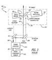
- Figure 3 is a block diagram showing an auto-boresight technique for the self-aligning phase conjugate laser, disclosed by Byren in U.S. Patent 4,798,462.
- the tracker is oriented to view the target by reflection off the same outcoupler device used in the self-aligning phase conjugate laser described above.
- a portion 309 of the master oscillator beam 301 is allowed to leak through the outcoupler 304 in order to provide a fudicial reference for the laser line of sight.
- This fudicial reference is sensed by the tracker (which must operate in-band to the laser) and is used as the boresight reference (or crosshairs) for tracking the target Due to the reflection symmetry at the outcoupler 304, when the target aimpoint line of sight 311 is aligned with the oscillator beam fudicial reference, the high power beam 303 will hit the target aimpoint. With this approach, boresight errors associated with the oscillator, outcoupler, and tracker are automatically corrected.
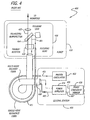
- Figure 4 shows a fiber beam cleanup scheme disclosed by Rockwell and Bartelt in U.S. Patent 5,208,699, entitled “Compensated, SBS-free Optical Beam Amplification and Delivery Apparatus and Method”.
- This system 400 may be used in a robotic industrial laser application in which a central station 409, containing a laser master oscillator 402, laser power amplifier 414, and phase conjugate mirror 416, delivers laser energy over a pair of optical delivery fibers 408 and 411 to the focusing head 418 of an industrial robot 410.
- the low power, high quality master oscillator beam 401 is delivered to the focusing head 418 through a low-power, single-mode, polarization-preserving optical fiber 411, This "reference" beam 401 is then reflected by a polarizing beamsplitter (outcoupler) 404 and the polarization is rotated by a non-iecipruca! polarizing element, such as a Faraday rotator 420, having the property that after two opposite passes through the element, the polarization is rotated 90 degrees.
- the low power beam 401 is then coupled into a large multi-mode delivery fiber 408 and delivered back to the central station 409, where it is amplified on a first pass through the amplifier beamline 414.
- the beam 405 is highly aberrated and depolarized due to optical phase distortions in the delivery fiber and power amplifiers.
- the beam 405 is then reflected by a vector phase conjugate mirror 416 that returns the phase conjugate of the incident wavefront with all polarization states remaining in the same phase relationship.
- the phase conjugated beam 407 then retraces its path to the focusing head 418, correcting for the optical distortions along the path.
- the amplified and corrected beam 403 then passes the non-reciprocal rotator and is outcoupled through the polarizing beamsplitter, emerging with essentially the same high beam quality as the reference beam 401 front the master oscillator 402.
- the advantage of this scheme is that the high brightness laser beam can now be focused to a small spot on the workpiece, while simultaneously providing a deep focal region and long working distance.
- the simultaneous provision of a small focused beam size, deep focal region, and long working distance are advantageous for robotic metal cutting applications where narrow kerf width, long standoff distances, and relaxed proximity tolerances enable faster cutting speeds, simplify programming of robotic motion, and reduce debris back-spatter on focusing lenses.
- FIG 5 is an operational diagram illustrating two applications of the teachings of the present invention.
- the application illustrated on the left side of the figure is one in which several elements of a high-energy laser such as a master oscillator (MO), a tracker, and outcoupler (none of which are shown in Figure 5) are integrated on a free-flying, unmanned platform 510 and a phase conjugate amplifier (not shown) is located on a second platform 520, e.g., a surface ship.
- This embodiment allows the HEL system 500 to engage anti-ship threats, such as sea-skimming cruise missiles 530, from above where the detection and engagement ranges are longer, the atmospheric turbulence and scattering is less, and the target is more vulnerable (side aspect).
- anti-ship threats such as sea-skimming cruise missiles 530
- An alternative application 500' is depicted in the right of the figure.
- the remote elements are integrated on a tethered un-manned rotocraft platform 510' and the phase conjugate amplifier is located on a second platform 520', in this case a combat vehicle such as a High Mobility Multi-Wheeled Vehicle (HMMWV).
- HMMWV High Mobility Multi-Wheeled Vehicle
- This embodiment allows the HMWWV to engage air and ground targets while protected by terrain features and provides a much larger field of engagement than afforded by a ground-based system.
- the tether may carry a fiber optic cable or bundle, which provides a flexible optical path between the remote airborne platform and surface-based platform.
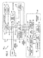
- FIG. 6 is a block diagram showing an illustrative implementation of a phase conjugate relay mirror system implemented in accordance with the teachings of the present invention.
- a lightweight and inexpensive relay mirror arrangement is located on a remote platform to redirect a high power electromagnetic (e.g. HEL) beam originating from a surface-based platform.
- HEL high power electromagnetic
- the invention is utilized in connection with a surface-based platform, those skilled in the art will appreciate that the invention is not limited thereto.
- the present teachings may be utilized with one or more platforms that are not located on a surface of a body without departing from the scope of the present teachings.
- the system 500 includes a master oscillator (MO) 502, an outcoupler 504, and a target track sensor 506 mounted on a remote platform 510.
- the remote platform 510 may be an unmanned aerial vehicle (UAV), tethered rotocraft or aerostat, elevated boom attached to a surface vehicle, elevated mast portion of a surface ship, space vehicle, or any other suitable manned or unmanned structure, articulating member, or craft without departing from the scope of the present teachings.
- the master oscillator 502, outcoupler 504 and target track sensor 506 are located on a stable platform 507.
- a conventional power supply 511 and cooling unit 513 are provided for the master oscillator 502 off the stable platform 507.
- the system 500 further includes a first beam director 508 located on the remote platform 510.
- a platform track sensor 509 is located on the beam director 508.
- the stable platform 507 is articulated relative to the body axes of the remote platform 510 by the beam director 508 through a mechanical linkage 515.
- the stable platform 507 is pointed in the direction of a target 550 by the beam director 508 under the control of a conventional servo processor 505 which receives angular error signal inputs from the target track sensor 506 and the platform track sensor 509.
- the beam director 508 therefore serves to orient the stable platform 507 such that the target track sensor's (506) line-of-sight (LOS) is pointed precisely toward the target aimpoint.
- LOS line-of-sight
- the beam director 508 also functions to coarsely point the LOS of the master oscillator beam 501 toward the surface-based platform 520 by means of a first platform track sensor 509 located on.
- the target track sensor 506, master oscillator 502, and outcoupler 5 04 are configured and aligned such that the master oscillator beam 501, after reflecting off the outcoupler 504, is co-aligned with the target track sensor line-of-sight (LOS).
- LOS line-of-sight
- a second beam director 522 is located on the surface-based platform 520.
- the second beam director 522 coarsely points the LOS of a phase conjugate amplifier beamline, consisting of a series of laser power amplifiers (amplifier beamline) 514 and a phase conjugate mirror 516, toward the remote platform 510 under the control of a conventional servo processor 526 with input from a second platform track sensor 524.
- the phase conjugate mirror 516 ensures that the amplified HEL beam 503, after double-passing the up-leg atmospheric path, the optics within the two beam directors, and the amplifier beamline, will propagate opposite the direction of the master oscillator beam 501, thus satisfying the alignment condition described above.
- the platform track sensors 509, 524 may use passive optical means to track the up-leg apertures of the surface-based platform 520 and remote platform 510, respectively; or may use active optical tracking means with the aid of additional optical alignment beams 525,527 located on the beam directors 508, 522.
- a conventional power supply 528 and a cooling unit 530 are provided for the amplifier beamline 514.
- the embodiment of Figure 6 may make use of the tracker auto-boresight approach described in Byren in above referenced U.S. patent 4,798,462 by using a portion 517 of the master oscillator beam 501 as the fudicial boresight reference (dashed arrow in Figure 6). If the master oscillator 502 operating wavelength is not within the target track sensor's passband, a separate alignment beam that is within said passband may be integrated within the master oscillator 502 and serve the function of the boresight reference. This allows the master oscillator 502 to be removed and replaced with minimal optical alignment and also enhances alignment retention, particularly if the boresight source and master oscillator 502 share a common pre-expanding telescope.
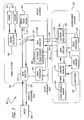
- Figure 7 shows an alternate embodiment of the invention, in which the master oscillator, target track sensor, and outcoupler are mounted directly on the remote platform, rather that on a stabilized platform that is articulated relative to the beam director.
- This embodiment may be advantageous for some applications requiring master oscillator and/or target track sensor components that are large and heavy and therefore inconvenient to mount on gimbal.
- a second beam director 610 is used to direct the line-of-sight of the target track sensor and HEL beam to the target.
- Figure 8 shows a second alternate embodiment of the invention.
- an optical fiber 710 or bundle of optical fibers is used to guide the lines of sight of the master oscillator and high power beams across the up-leg atmospheric path.
- This embodiment eliminates the need for the platform track sensors and associated beam directors to perform coarse line-of-sight control over the up-leg atmospheric path This is similar to the scheme disclosed by Rockwell and Bartelt in U.S. Patent 5,208,699.
- this embodiment includes the fiber cable as part of the remote vehicle tether, a feature not shown, disclosed, nor anticipated by Rockwell and Bartelt.
- the line-of-sight control, high-power optics, optical imaging, tracking, lasing, power generation, and cooling components and software as well as the HEL pointing and tracking techniques used in this invention, and illustrated in the above-referenced embodiments, maybe a conventional design and construction.
Landscapes
- Engineering & Computer Science (AREA)
- Radar, Positioning & Navigation (AREA)
- Remote Sensing (AREA)
- General Engineering & Computer Science (AREA)
- Physics & Mathematics (AREA)
- Optics & Photonics (AREA)
- Aviation & Aerospace Engineering (AREA)
- Lasers (AREA)
Claims (10)
- System (500) zur Ausrichtung elektromagnetischer Energie, wobei das System folgendes enthält:ein erstes Untersystem, welches auf einer ersten Plattform (520) angeordnet ist, zum Empfang eines Laserstrahls (501), zum Verstärken des Laserstrahls zur Bildung eines verstärkten Strahles (503) und zur Übertragung des verstärkten Strahles (503) über ein Medium; undein zweites Untersystem, welches auf einer zweiten Plattform (510) angeordnet ist, zum Neuausrichten des verstärkten Strahles (503), wobei die zweite Plattform (510) relativ zu der ersten Plattform (520) beweglich ist; wobeidas genannte erste Untersystem einen Phasenkonjugationsspiegel (516) in optischer Ausrichtung mit einer Laserverstärker-Strahllinie (514) enthält; unddas zweite Untersystem einen Hauptoszillator (502) enthält, um den genannten Laserstrahl (501) zu erzeugen.
- Erfindung nach Anspruch 1, bei welcher das zweite Untersystem einen Relaisspiegel (504) und eine Strahlausrichtungseinrichtung (508) enthält.
- Erfindung nach Anspruch 2, bei welcher das zweite Untersystem weiter einen Plattform-Bahnsensor (509) enthält.
- Erfindung nach Anspruch 3, bei welcher das zweite Untersystem weiter einen Zielobjekt-Bahnsensor (506) enthält.
- Erfindung nach Anspruch 1, bei welcher das zweite Untersystem erste und zweite Strahlausrichteinrichtungen enthält, wobei die erste Strahlausrichteinrichtung (508) so ausgebildet ist, dass sie den verstärkten Strahl empfängt, und die zweite Strahlausrichteinrichtung (610) so ausgebildet ist, dass sie eine Neuausrichtung des verstärkten Strahles vornimmt.
- Erfindung nach Anspruch 1, bei welcher das genannte erste Untersystem weiter eine Strahlausrichteinrichtung (522) in optischer Ausrichtung mit der genannten Laserverstärker-Strahllinie (514) enthält.
- Erfindung nach Anspruch 6, bei welcher die genannte Strahlausrichteinrichtung (522) einen Plattform-Bahnsensor (524) enthält.
- Verfahren zur Ausrichtung elektromagnetischer Energie, wobei das Verfahren folgende Schritte enthält:Erzeugen eines Laserstrahls (501) mit einem Hauptoszillator auf einer sekundären Plattform (510);Übertragen des Strahls (501) durch ein Medium zu einer ersten Plattform (520);Verstärken des genannten Strahls mit einer phasenkonjugierten Verstärker-Strahllinie auf der ersten Plattform (520) zur Bildung eines verstärkten Strahles (503);Übertragen des genannten verstärkten Strahles (503) von der ersten Plattform (520) durch das genannte Medium zu der genannten zweiten oder sekundären Plattform (510); undNeuausrichten des genannten Strahles von der genannten zweiten Plattform (510), welche relativ zu der genannten ersten Plattform (520) beweglich ist.
- Verfahren nach Anspruch 8, bei welchem die Schritte der Übertragung des Strahles (501) und der Übertragung des genannten verstärkten Strahles (503) das Übertragen der Strahlen durch die Atmosphäre umfasst.
- Verfahren nach Anspruch 8, bei welchem die Schritte der Übertragung des genannten Strahles (501) und der Übertragung des genannten verstärkten Strahles (503) die Übertragung der Strahlen durch mindestens ein faseroptisches Kabel (710) umfassen.
Applications Claiming Priority (3)
| Application Number | Priority Date | Filing Date | Title |
|---|---|---|---|
| US10/272,778 US6961171B2 (en) | 2002-10-17 | 2002-10-17 | Phase conjugate relay mirror apparatus for high energy laser system and method |
| US272778 | 2002-10-17 | ||
| PCT/US2003/033010 WO2004036703A2 (en) | 2002-10-17 | 2003-10-17 | Phase conjugate relay mirror apparatus for high energy laser system and method |
Publications (2)
| Publication Number | Publication Date |
|---|---|
| EP1556929A2 EP1556929A2 (de) | 2005-07-27 |
| EP1556929B1 true EP1556929B1 (de) | 2007-04-04 |
Family
ID=32092661
Family Applications (1)
| Application Number | Title | Priority Date | Filing Date |
|---|---|---|---|
| EP03777656A Expired - Lifetime EP1556929B1 (de) | 2002-10-17 | 2003-10-17 | Phasenkonjugierte relaisspiegel-vorrichtung für hochenergie-lasersystem und verfahren |
Country Status (5)
| Country | Link |
|---|---|
| US (1) | US6961171B2 (de) |
| EP (1) | EP1556929B1 (de) |
| DE (1) | DE60313013T2 (de) |
| IL (1) | IL165577A0 (de) |
| WO (1) | WO2004036703A2 (de) |
Families Citing this family (28)
| Publication number | Priority date | Publication date | Assignee | Title |
|---|---|---|---|---|
| US7002127B2 (en) * | 2002-07-19 | 2006-02-21 | Lockheed Corp | Method and system for wavefront compensation |
| CN1316282C (zh) * | 2005-05-31 | 2007-05-16 | 哈尔滨工业大学 | 收发离轴式卫星光通信跟瞄装置 |
| US7629918B2 (en) * | 2005-12-15 | 2009-12-08 | Raytheon Company | Multifunctional radio frequency directed energy system |
| US20070183783A1 (en) * | 2006-02-07 | 2007-08-09 | Raytheon Company | Netted communication and weapons system for littoral warfare |
| CA2669898C (en) * | 2007-01-24 | 2012-04-03 | Raytheon Company | Multifunctional radio frequency directed energy system |
| US7978313B2 (en) * | 2008-05-30 | 2011-07-12 | The Boeing Company | Systems and methods for targeting directed energy devices |
| AU2009294243A1 (en) * | 2008-09-19 | 2010-03-25 | Shilat Imaging Ltd | Aerial observation system |
| US7929125B2 (en) * | 2008-11-26 | 2011-04-19 | Raytheon Company | Gimbaled system with optical coudé path and method transferring data |
| US8203109B2 (en) * | 2009-05-08 | 2012-06-19 | Raytheon Company | High energy laser beam director system and method |
| KR101200943B1 (ko) * | 2010-04-06 | 2012-11-13 | 한국과학기술원 | 고에너지 레이저 요격 장치 및 그 방법 |
| US8923359B1 (en) * | 2010-08-06 | 2014-12-30 | Lockheed Martin Corporation | Long cavity laser sensor for large FOV auto-tracking |
| US8635938B2 (en) | 2011-05-25 | 2014-01-28 | Raytheon Company | Retractable rotary turret |
| US8654314B2 (en) * | 2011-05-25 | 2014-02-18 | Raytheon Company | Rapidly deployable high power laser beam delivery system |
| US9535211B2 (en) | 2011-12-01 | 2017-01-03 | Raytheon Company | Method and apparatus for fiber delivery of high power laser beams |
| US9664869B2 (en) | 2011-12-01 | 2017-05-30 | Raytheon Company | Method and apparatus for implementing a rectangular-core laser beam-delivery fiber that provides two orthogonal transverse bending degrees of freedom |
| DE102012006352B4 (de) * | 2012-03-28 | 2014-07-17 | Mbda Deutschland Gmbh | Vorrichtung zum Testen und/oder Betreiben einer Wirkeinheit |
| US8983259B2 (en) * | 2012-05-04 | 2015-03-17 | Raytheon Company | Multi-function beam delivery fibers and related system and method |
| DE102012015074C5 (de) | 2012-07-31 | 2018-03-29 | Mbda Deutschland Gmbh | Neuartige Strahleinrichtung für ein Laserwaffensystem |
| EP2912519B1 (de) | 2012-10-23 | 2023-08-02 | Israel Aerospace Industries Ltd. | Optisches zeigesystem |
| IL226991A (en) | 2013-06-17 | 2016-08-31 | Israel Aerospace Ind Ltd | Laser conjured show |
| DE102013016646A1 (de) * | 2013-10-05 | 2015-04-09 | Mbda Deutschland Gmbh | Luftgestütztes Laserwaffensystem |
| US10004136B2 (en) | 2015-02-02 | 2018-06-19 | Michael McCrea | Satellite-based ballistic missile defense system |
| US20180252504A1 (en) * | 2016-04-28 | 2018-09-06 | Kiwamu Takehisa | Laser defense system and high altitude airship |
| CN106788700B (zh) * | 2016-11-17 | 2019-04-02 | 哈尔滨工业大学 | 卫星激光通信捕获性能地面小样本测试方法 |
| CN109960031B (zh) * | 2019-04-28 | 2024-02-09 | 湖南谱峰光电有限公司 | 浮空器激光中继镜系统及其仿真装置和仿真方法 |
| US12113280B2 (en) | 2019-05-23 | 2024-10-08 | Bae Systems Plc | Airborne redirection unit for deflecting a radio frequency energy beam |
| CN110567317B (zh) * | 2019-09-19 | 2022-05-06 | 中国航空工业集团公司西安飞机设计研究所 | 一种激光武器 |
| GB2590956B (en) * | 2020-01-09 | 2022-06-29 | Thales Holdings Uk Plc | Guidance head and method |
Citations (1)
| Publication number | Priority date | Publication date | Assignee | Title |
|---|---|---|---|---|
| US4949056A (en) * | 1985-07-29 | 1990-08-14 | The Perkin-Elmer Corporation | Unconventional adaptive optics |
Family Cites Families (11)
| Publication number | Priority date | Publication date | Assignee | Title |
|---|---|---|---|---|
| US4812639A (en) * | 1985-12-19 | 1989-03-14 | Hughes Aircraft Company | Self-aligning phase conjugate laser |
| US4853528A (en) * | 1985-12-19 | 1989-08-01 | Hughes Aircraft Company | Self-aligning phase conjugate laser |
| US4798462A (en) * | 1985-12-20 | 1989-01-17 | Hughes Aircraft Company | Auto-boresight technique for self-aligning phase conjugate laser |
| US4734911A (en) * | 1986-03-14 | 1988-03-29 | Hughes Aircraft Company | Efficient phase conjugate laser |
| US5557347A (en) | 1986-11-04 | 1996-09-17 | The Charles Stark Draper Laboratory, Inc. | Ballistic missile boresight and inertial tracking system and method |
| IL96186A (en) * | 1989-11-20 | 1994-08-26 | Hughes Aircraft Co | Master oscillator power amplifier with interference isolated oscillator |
| US5208699A (en) * | 1991-12-20 | 1993-05-04 | Hughes Aircraft Company | Compensated, SBS-free optical beam amplification and delivery apparatus and method |
| US5483342A (en) * | 1993-06-25 | 1996-01-09 | Hughes Aircraft Company | Polarization rotator with frequency shifting phase conjugate mirror and simplified interferometric output coupler |
| US5557357A (en) * | 1993-12-14 | 1996-09-17 | Nikon Corporation | Camera having anti-vibration function with improved connection and placement of anti-vibration components |
| US6219360B1 (en) * | 1998-04-24 | 2001-04-17 | Trw Inc. | High average power solid-state laser system with phase front control |
| DE10049275A1 (de) * | 2000-09-28 | 2002-04-18 | Lzh Laserzentrum Hannover Ev | Einrichtung und Verfahren zur Verstärkung kurzer, insbesondere ultrakurzer Laserpulse |
-
2002
- 2002-10-17 US US10/272,778 patent/US6961171B2/en not_active Expired - Lifetime
-
2003
- 2003-10-17 WO PCT/US2003/033010 patent/WO2004036703A2/en not_active Ceased
- 2003-10-17 EP EP03777656A patent/EP1556929B1/de not_active Expired - Lifetime
- 2003-10-17 DE DE60313013T patent/DE60313013T2/de not_active Expired - Lifetime
-
2004
- 2004-12-06 IL IL16557704A patent/IL165577A0/xx unknown
Patent Citations (1)
| Publication number | Priority date | Publication date | Assignee | Title |
|---|---|---|---|---|
| US4949056A (en) * | 1985-07-29 | 1990-08-14 | The Perkin-Elmer Corporation | Unconventional adaptive optics |
Also Published As
| Publication number | Publication date |
|---|---|
| EP1556929A2 (de) | 2005-07-27 |
| WO2004036703A3 (en) | 2004-07-08 |
| IL165577A0 (en) | 2006-01-15 |
| US6961171B2 (en) | 2005-11-01 |
| WO2004036703B1 (en) | 2004-09-10 |
| WO2004036703A2 (en) | 2004-04-29 |
| US20040075884A1 (en) | 2004-04-22 |
| DE60313013D1 (de) | 2007-05-16 |
| DE60313013T2 (de) | 2007-12-13 |
Similar Documents
| Publication | Publication Date | Title |
|---|---|---|
| EP1556929B1 (de) | Phasenkonjugierte relaisspiegel-vorrichtung für hochenergie-lasersystem und verfahren | |
| US7688247B2 (en) | Fiber laser based directional infrared countermeasure (DIRCM) system | |
| Ahmed et al. | Survey and technological analysis of laser and its defense applications | |
| EP2726810B1 (de) | Aktives retrodirektives antennenarray mit einer virtuellen bake | |
| KR101057303B1 (ko) | 레이저무기용 추적조준장치 | |
| US5600434A (en) | Apparatus for defending against an attacking missile | |
| US8284382B2 (en) | Lookdown and loitering LADAR system | |
| US7336345B2 (en) | LADAR system with SAL follower | |
| Coffey | High-energy lasers: new advances in defense applications | |
| US5557347A (en) | Ballistic missile boresight and inertial tracking system and method | |
| US7742151B2 (en) | Laser-based system with LADAR and SAL capabilities | |
| IL279319B2 (en) | Optical Pointing and Tracking System | |
| EP1816761A2 (de) | Vernetzte Kommunikation und Waffensystem für Kriegsführung in Küstenzonen | |
| US7477368B2 (en) | Relayed pupil optical control system | |
| CN112923797B (zh) | 基于反射镜稳定的小型共光路定向红外对抗转塔 | |
| US4729647A (en) | Retrofit optical turret with laser source | |
| US7821623B2 (en) | Surveillance satellite image denial system | |
| Zimet | High-energy lasers: technical, operational, and policy issues | |
| Maini | Battlefield lasers and opto-electronics systems | |
| KR102926365B1 (ko) | 고속 조향경을 이용하는 레이저 표적 지시 장치 및 이를 포함하는 시스템 | |
| Mallik | Lasers in defense | |
| Summers | How is US Space Power Jeopardized by an Adversary; s Exploitation, Technological Developments, Employment, and Engagement of Laser Antisatellite Weapons? | |
| PENTAGON | i Vtl/VV VUMLU VIS IAS AIR AND SPACE POWER FORTHE | |
| WO2025104161A1 (en) | Systems, devices, and methods for space security | |
| Maini et al. | Lasers in defence: an overview of contemporary status and emerging trends |
Legal Events
| Date | Code | Title | Description |
|---|---|---|---|
| PUAI | Public reference made under article 153(3) epc to a published international application that has entered the european phase |
Free format text: ORIGINAL CODE: 0009012 |
|
| 17P | Request for examination filed |
Effective date: 20050211 |
|
| AK | Designated contracting states |
Kind code of ref document: A2 Designated state(s): AT BE BG CH CY CZ DE DK EE ES FI FR GB GR HU IE IT LI LU MC NL PT RO SE SI SK TR |
|
| RBV | Designated contracting states (corrected) |
Designated state(s): DE FR GB |
|
| GRAP | Despatch of communication of intention to grant a patent |
Free format text: ORIGINAL CODE: EPIDOSNIGR1 |
|
| RIN1 | Information on inventor provided before grant (corrected) |
Inventor name: BYREN, ROBERT, W. Inventor name: FILGAS, DAVID |
|
| GRAS | Grant fee paid |
Free format text: ORIGINAL CODE: EPIDOSNIGR3 |
|
| GRAA | (expected) grant |
Free format text: ORIGINAL CODE: 0009210 |
|
| AK | Designated contracting states |
Kind code of ref document: B1 Designated state(s): DE FR GB |
|
| REG | Reference to a national code |
Ref country code: GB Ref legal event code: FG4D |
|
| REF | Corresponds to: |
Ref document number: 60313013 Country of ref document: DE Date of ref document: 20070516 Kind code of ref document: P |
|
| ET | Fr: translation filed | ||
| PLBE | No opposition filed within time limit |
Free format text: ORIGINAL CODE: 0009261 |
|
| STAA | Information on the status of an ep patent application or granted ep patent |
Free format text: STATUS: NO OPPOSITION FILED WITHIN TIME LIMIT |
|
| 26N | No opposition filed |
Effective date: 20080107 |
|
| REG | Reference to a national code |
Ref country code: FR Ref legal event code: PLFP Year of fee payment: 14 |
|
| REG | Reference to a national code |
Ref country code: FR Ref legal event code: PLFP Year of fee payment: 15 |
|
| REG | Reference to a national code |
Ref country code: FR Ref legal event code: PLFP Year of fee payment: 16 |
|
| PGFP | Annual fee paid to national office [announced via postgrant information from national office to epo] |
Ref country code: FR Payment date: 20180913 Year of fee payment: 16 |
|
| PGFP | Annual fee paid to national office [announced via postgrant information from national office to epo] |
Ref country code: DE Payment date: 20181002 Year of fee payment: 16 |
|
| PGFP | Annual fee paid to national office [announced via postgrant information from national office to epo] |
Ref country code: GB Payment date: 20181017 Year of fee payment: 16 |
|
| REG | Reference to a national code |
Ref country code: DE Ref legal event code: R119 Ref document number: 60313013 Country of ref document: DE |
|
| PG25 | Lapsed in a contracting state [announced via postgrant information from national office to epo] |
Ref country code: DE Free format text: LAPSE BECAUSE OF NON-PAYMENT OF DUE FEES Effective date: 20200501 |
|
| GBPC | Gb: european patent ceased through non-payment of renewal fee |
Effective date: 20191017 |
|
| PG25 | Lapsed in a contracting state [announced via postgrant information from national office to epo] |
Ref country code: FR Free format text: LAPSE BECAUSE OF NON-PAYMENT OF DUE FEES Effective date: 20191031 Ref country code: GB Free format text: LAPSE BECAUSE OF NON-PAYMENT OF DUE FEES Effective date: 20191017 |