EP1557111A1 - Applikator mit einem Auftragselement, welcher mit einem Produktbehälter verbunden ist - Google Patents
Applikator mit einem Auftragselement, welcher mit einem Produktbehälter verbunden ist Download PDFInfo
- Publication number
- EP1557111A1 EP1557111A1 EP05300052A EP05300052A EP1557111A1 EP 1557111 A1 EP1557111 A1 EP 1557111A1 EP 05300052 A EP05300052 A EP 05300052A EP 05300052 A EP05300052 A EP 05300052A EP 1557111 A1 EP1557111 A1 EP 1557111A1
- Authority
- EP
- European Patent Office
- Prior art keywords
- applicator
- container
- applicator according
- skirt
- plug
- Prior art date
- Legal status (The legal status is an assumption and is not a legal conclusion. Google has not performed a legal analysis and makes no representation as to the accuracy of the status listed.)
- Granted
Links
Images


Classifications
-
- A—HUMAN NECESSITIES
- A45—HAND OR TRAVELLING ARTICLES
- A45D—HAIRDRESSING OR SHAVING EQUIPMENT; EQUIPMENT FOR COSMETICS OR COSMETIC TREATMENTS, e.g. FOR MANICURING OR PEDICURING
- A45D34/00—Containers or accessories specially adapted for handling liquid toiletry or cosmetic substances, e.g. perfumes
- A45D34/04—Appliances specially adapted for applying liquid, e.g. using roller or ball
- A45D34/042—Appliances specially adapted for applying liquid, e.g. using roller or ball using a brush or the like
-
- A—HUMAN NECESSITIES
- A45—HAND OR TRAVELLING ARTICLES
- A45D—HAIRDRESSING OR SHAVING EQUIPMENT; EQUIPMENT FOR COSMETICS OR COSMETIC TREATMENTS, e.g. FOR MANICURING OR PEDICURING
- A45D19/00—Devices for washing the hair or the scalp; Similar devices for colouring the hair
- A45D19/02—Hand-actuated implements, e.g. hand-actuated spray heads
- A45D19/026—Hand-actuated implements, e.g. hand-actuated spray heads having brush or comb applicators
-
- A—HUMAN NECESSITIES
- A45—HAND OR TRAVELLING ARTICLES
- A45D—HAIRDRESSING OR SHAVING EQUIPMENT; EQUIPMENT FOR COSMETICS OR COSMETIC TREATMENTS, e.g. FOR MANICURING OR PEDICURING
- A45D29/00—Manicuring or pedicuring implements
-
- B—PERFORMING OPERATIONS; TRANSPORTING
- B65—CONVEYING; PACKING; STORING; HANDLING THIN OR FILAMENTARY MATERIAL
- B65D—CONTAINERS FOR STORAGE OR TRANSPORT OF ARTICLES OR MATERIALS, e.g. BAGS, BARRELS, BOTTLES, BOXES, CANS, CARTONS, CRATES, DRUMS, JARS, TANKS, HOPPERS, FORWARDING CONTAINERS; ACCESSORIES, CLOSURES, OR FITTINGS THEREFOR; PACKAGING ELEMENTS; PACKAGES
- B65D47/00—Closures with filling and discharging, or with discharging, devices
- B65D47/42—Closures with filling and discharging, or with discharging, devices with pads or like contents-applying means
-
- A—HUMAN NECESSITIES
- A45—HAND OR TRAVELLING ARTICLES
- A45D—HAIRDRESSING OR SHAVING EQUIPMENT; EQUIPMENT FOR COSMETICS OR COSMETIC TREATMENTS, e.g. FOR MANICURING OR PEDICURING
- A45D2200/00—Details not otherwise provided for in A45D
- A45D2200/05—Details of containers
- A45D2200/051—Airtight containers
-
- A—HUMAN NECESSITIES
- A45—HAND OR TRAVELLING ARTICLES
- A45D—HAIRDRESSING OR SHAVING EQUIPMENT; EQUIPMENT FOR COSMETICS OR COSMETIC TREATMENTS, e.g. FOR MANICURING OR PEDICURING
- A45D2200/00—Details not otherwise provided for in A45D
- A45D2200/05—Details of containers
- A45D2200/053—Transparent containers
-
- A—HUMAN NECESSITIES
- A45—HAND OR TRAVELLING ARTICLES
- A45D—HAIRDRESSING OR SHAVING EQUIPMENT; EQUIPMENT FOR COSMETICS OR COSMETIC TREATMENTS, e.g. FOR MANICURING OR PEDICURING
- A45D2200/00—Details not otherwise provided for in A45D
- A45D2200/10—Details of applicators
- A45D2200/1009—Applicators comprising a pad, tissue, sponge, or the like
- A45D2200/1018—Applicators comprising a pad, tissue, sponge, or the like comprising a pad, i.e. a cushion-like mass of soft material, with or without gripping means
Definitions
- the present invention relates to the applicators of a liquid product, especially a cosmetic and / or care product.
- Cosmetic product is meant within the meaning of the present invention a product as defined in Directive 93/35 / EEC of 14 June 1993 amending Directive 76/768 / EEC.
- Cosmetics include, in particular, cosmetics skin or skin appendages.
- Care products include those intended to be applied on the human or animal body to treat or prevent a pathology.
- Applicators whose application element is carried by a plug of closure of a container containing the product to be applied are known, in particular French patents 940 464 and 2 585 934 and US Pat. No. 5,345,981. These applicators are relatively complex manufacturing and may for some not offer autonomy sufficient.
- the invention aims in particular to meet this need.
- the container comprises at least one feed channel of the application element, this channel being in communication with the interior of the container when the cap closes the container and opening directly outside the element application, this channel being arranged so as to be able to bring the product contained in the container on the outer periphery of the application element.
- the invention may allow the user to exercise visual control over the amount of product that is delivered to the application element during use, this which makes it easier to obtain quality makeup.
- the relatively small inner volume of the cap reduces the risk of drying a residual quantity of product possibly present on the application element, in the absence of use.
- the cap can for example, when it closes the container, be at least partially filled with the product to be applied so that the application element may remain soaked with product during storage, even if the container is almost empty.
- the supply of the product to the outer periphery of the application element can to further facilitate attachment of the latter to the container, allowing for example, in the case of an application element comprising a tuft of bristles, the fixation of the latter by stapling in the bottom of a housing provided for this purpose on the container.
- the product contained in the container can be brought into the housing of the plug by the aforementioned channel, so that the housing may be at least partially filled with the product when the closure closes the container.
- the channel is configured in such a way it allows the product to flow by gravity into the housing of the cap.
- all the product contained in the applicator can be contained in the recipient.
- the wall of the container may be in contact with the product to be applied. Volume inside the cap is too weak to receive all the product contained in the applicator.
- the container comprises several supply channels of the application element, these channels being for example equidistributed angularly about a longitudinal axis of the applicator.
- the fluid communication between the housing of the cap which receives the application element and the interior space of the container can be carried out exclusively by said supply channel.
- the length of the container is at least double that of the cap.
- a relatively elongated container can facilitate the user's pressure on the wall, to create in the container an overpressure tending to drive the product through said at least one channel Power.
- the container may comprise an application element holder and said at least one Feed channel can be formed in this holder application element.
- the container may include a container body and an adapter which is attached on the container body and which allows the removable attachment of the cap.
- an adapter allow, where appropriate, to benefit from economies of scale by using a same adapter for several container bodies and / or application element holder different.
- the application element holder can be attached to this adapter or variant be made in one piece by molding plastic material with the adapter.
- the adapter can be fixed for example by screwing or snapping on the body of the container.
- the adapter may comprise an annular sealing lip arranged for apply sealingly against a neck of the container body.
- the cap may be arranged to screw onto the container, in particular on the adapter.
- the cap may in particular be configured to screw on a threaded skirt internally, which may reduce the risk of the user getting dirty during assembly and disassembly of the cap.
- the stopper is arranged to apply sealingly on the container, in particular on the application element holder and / or the adapter.
- the plug can be made at least partially of a material transparent, for example a plastic or glass.
- the cap can still be made entirely of a transparent material.
- the cap may comprise a body and a capsule attached to this body, this capsule defining for example at least partially the top of the cap.
- This capsule may carry, for example, a label or a color indicator pad and / or a reference of the product contained in the container.
- the capsule may contribute nothing to the closure of the container, being example engaged on a central part closed upper body of the cap.
- the capsule can contribute to the closure of the container and include for example a skirt sealingly applied to a corresponding skirt of the body of the cap.
- the capsule may be at least partially transparent.
- the cap may comprise, in a particular embodiment, a skirt outer and an inner skirt connecting superiorly to the outer skirt.
- the skirt outer can be arranged to screw on a threaded skirt outside the container, including the adapter, and the cap may further comprise a body engaged in the inner skirt, this body being for example arranged to apply sealingly against the application element holder.
- the plug can still, in another example of implementation, include an inner skirt and an outer skirt connecting lower than the inner skirt.
- the latter can be arranged to be screwed onto a threaded skirt internally of the container, including the adapter.
- the cap may have several inserts on top of each other, as stated above, or be monolithic.
- the application element holder may comprise, in one embodiment particular, a flange intended to abut against a transverse wall of the adapter.
- the cap can be applied to this collar at the end of its screwing, this flange which can, if necessary, contribute to the sealing of the closure of the container, especially if it is made of a flexible material.
- the aforesaid transverse wall may comprise an annular lip, in order to to further increase the tightness of the attachment of the application element holder on the adapter.
- the application element holder may comprise at least one relief, for example an annular bead, arranged to snap on the aforementioned transverse wall.
- the cap may comprise a sealing surface arranged to apply on the application element holder.
- This sealing surface may be for example a surface defined by a sealing lip or a conical surface.
- the application element holder may also, where appropriate, include a lip annular sealing arranged to apply against the plug when it is in square.
- the application element holder may comprise, in a particular mode of implementation of the invention, a skirt partially covering the application element and defining a housing for fixing it to the element holder application.
- Said at least one supply channel of the application element extend at least partially on the outer surface of this skirt, which can help to channel the product to a predetermined area of the application element, this which may be useful especially when the application element has a shape particular, for example non-symmetrical of revolution.
- the application element holder may comprise, when the channels are multiple, at least two legs between which extend said channels, or at least three legs.
- tabs can help the product to flow to the application element, thanks to a capillary retention between them, when the applicator is oriented with the element applied downwards with its longitudinal axis at approximately 45 ° from the vertical, for example.
- the tabs have a external face oriented obliquely towards the application element.
- the housing of the application element holder, in which the element is received application may comprise a side wall, constituted for example by the skirt and / or by the aforementioned tabs, and a bottom wall which may be thicker than the side wall, this may allow for example the application element holder to resist fixation a staple for holding a bundle of bristles on the applicator element holder.
- the legs may be provided, in the vicinity of their free end, with surfaces directed towards the application element, in order to further improve the feeding of the application element into product.
- the container may have two supply channels diametrically opposed.
- the application element can be attached to an attached part on an element holder application, the latter preferably having inner fins helping to ensure that fixation.
- the container may have a tubular wall extending along a portion at least the length of the application element to distribute the product delivered by the the supply channels around the application element.
- the tubular wall may in particular extend in front of the receiving part the application element and reported in the application element holder.
- This wall tubular can be connected at its base to a substantially frustoconical wall of the element-holder application.
- an applicator container containing a product to be applied, an application element fixed on the container at least during use, a cap for closing the container, the latter having at least one product supply channel of the application element, this channel being in communication with the interior of the container, this channel being disposed of in order to bring the product contained in the container to the outer circumference of the application element, the application element being fixed in a housing of an element holder application having at least one part, for example frustoconical, reducing the inner section offered by the application element holder to the passage of the product.
- This reduction of section can make it possible to benefit from a section relatively broad upstream, so to reduce the pressure drop and to favor the flow of the product, if necessary.
- Another subject of the invention is an applicator container containing a product to be applied, an application element fixed on the container at least during use, a cap to close the container, the container having a plurality of product supply channels of the application element, arranged to bring the product contained in the container to the outer periphery of the application element.
- an applicator container containing a product to be applied, an application element fixed on the container at least during use, a cap to close the container, the container having at least one product supply channel of the application element, this channel being in fluid communication with the interior of the container, this channel being furthermore arranged to bring the product contained in the container to the outer periphery of the applicator element, the container comprising a container body provided with a collar and an adapter having a mounting skirt in which the neck is fixed.
- said at least one channel extends in a direction substantially parallel to the axis defined by the application element.
- said at least one channel is configured so that the product can be brought from the container to and from the outside rim of the application element.
- Said at least one channel may comprise, in an exemplary embodiment, a portion having a tubular cross-section and a portion having a section transverse open on the side.
- the at least one channel may include a plurality of channels.
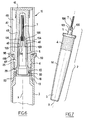
- the applicator 1 shown in FIG. 1 comprises a container 2 composed of a container body 3, an adapter 4 fixed to the container body 3 and an element holder 5 attached to the adapter 4.
- An application element 7 is fixed in a housing 8 of the element-holder of application 5.
- a closure cap 10 composed in the example considered of a body of cap 11 and a capsule 12 attached to it, can close tightly the container.
- the application element 7 is for example a bundle of bristles, the bristles being of the same nature or of different natures, straight or wavy, arranged so as to constitute a brush for the application of product on the nails.
- the invention is not limited to a particular application element 7 and can use application elements 7 of all kinds and shapes, such as for example flocked tips, foams, felts, brushes, soft spikes, this list not being limiting.
- the container body 3 has been shown only partially in FIG. preferably has a generally elongated shape along the longitudinal axis X of the applicator 1.
- the body of the container 3 is made by extrusion / blowing with a neck 13 and a flexible wall 14 with shape memory on which the user can exert pressure to reduce its internal volume and force the product distribution contained in it on the application element 7, like this will be specified later.
- the invention is not limited to the embodiment of the container body 3 by extrusion / blowing and this can be achieved by other techniques, for example example by injection, in one or more thermoplastics or thermosetting, glass or ceramic or in metals.
- the product contained in the container body 3 is for example a varnish to nails but it is not beyond the scope of the present invention when this product is a other liquid, for example a solvent or more generally any other product cosmetic or skincare or even a non-cosmetic product, for example a paint for touch up on a car body.
- the container body 3 can accommodate a ball for homogenizing its content, if any.
- the adapter 4 is snap-fastened to the neck 13, the latter having for this purpose an annular groove 15 in which snap reliefs 16 of the adapter 4, these reliefs 16 being carried by a mounting skirt 20, tubular X axis.
- the mounting skirt 20 could be discontinuous and having attachment tabs on the container body 3.
- the adapter 4 may further comprise, as illustrated, an annular lip sealing member 18 intended to be applied on the inner surface of the neck 13 and the ribs 19 intended to clamp the neck 13, these ribs being formed on the mounting skirt 20.
- the ribs 19 prevent the adapter 4 from rotating relative to the neck 13, during the unscrewing the plug 10.
- a transverse wall 22 extends perpendicularly to the X axis, is connected to the skirt 20 and supports the sealing lip 18. This transverse wall 22 defines an opening 23.
- the adapter 4 also comprises a skirt 25 for receiving the plug 10, threaded internally in the example of Figure 1, in which can screw the cap 10.
- This skirt 25 extends in the extension of the skirt 20, above the wall cross section 22.
- the applicator element holder 5 comprises a tubular part 28 which passes through the opening 23 and carries a flange 29 which bears axially on the face upper part of the transverse wall 22, as illustrated.
- the tubular portion 28 has an annular bead 30 which is snapped under the transverse wall 22, in order to retain the application element holder 5 on the adapter 4.
- the outer diameter of the tubular portion 28 substantially corresponds to that of the opening 23.
- the transverse wall 22 carries a small annular lip 60 to improve still sealing the mounting of the application element holder 5 on the adapter 4 in closed position.
- tubular portion 28 is connected by a part frustoconical 33 to an upper portion 34, full, which defines the bottom of the housing 8 receiving the application element 7.
- This portion 34 is extended further by a skirt 36 which defines the side wall of housing 8 and partially covers the element of application 7.
- the inner cross section of the housing 8 is circular of axis X in the example considered.
- the portion 34 is crossed by a channel 40 for supplying product of the application element 7.
- This channel 40 extends in the illustrated example parallel to the axis X, which can facilitate its realization by molding and opens inside the element holder 5 substantially at the top of the frustoconical portion 33, passes through the portion 34 and continues along the skirt 36, being open radially outwardly on its portion 66 extending over the skirt 36.
- the portion 34 is delimited externally by a frustoconical surface 42, on which the channel 40 opens through an orifice 65 before extending along the skirt 36.
- the section of the orifice 65 is adapted to the viscosity of the product contained in the container, so that the product flow is not too large when the container came back.
- the channel 40 also allows a return of air, when the container body elastically resumes its original shape.
- the pressure drop suffered by the product is relatively small, being mainly caused by the crossing part 34.
- the plug body 11 comprises a neck 43, threaded externally, which is screwed into the skirt 25 and which applies at the end of the screwing of the plug 10, by its radially inner surface 44, against the tubular portion 28 and by its end wafer 45 against the collar 29. This makes it possible to obtain a tight closure of the container.
- the neck 43 is extended on the one hand on the one hand by an outer skirt 47, the latter being in the example considered cylindrical of revolution about the axis X, and on the other hand by an inner skirt 48, defining with the outer skirt 47 a space annular 49.
- the inner skirt 48 is closed topally by an upper wall 50, set back from the upper end 52 of the outer skirt 47.
- the capsule 12 has a skirt 54 which is frictionally engaged on the inner skirt 48, in the annular space 49. capsule 12 rests against the upper wall 50, the outer face 55 of this capsule 12 coming substantially flush with the upper end 52 of the outer skirt 47.
- the inner skirt 48 defines, with the upper wall 50, a housing 58 in which extends the application element 7, the housing 58 having a sufficient height so that the application element 7 keeps its upper end set back from the wall upper 50, as can be seen in Figure 1.
- the volume of this housing 58 is relatively small, being for example more than five times smaller than that of the container body 3, being for example less than 1 cm 3 , while the capacity of the container is for example greater than 5 cm 3 .
- the plug body 11 may be made of a plastic material transparent and the capsule 12 may carry a pellet indicative of the color of the product, this pellet comprising for example a deposit of the same product as that contained in the container.
- the adapter 4 is screwed onto the neck 43, which pushes the bead annular 30 through the transverse wall 22.
- the assembly thus formed can be returned and snap-fastened to the container body 3, which has been filled with the product to apply.
- the user unscrews the cap 10 and can return the container 2 so as to point the applicator element 7 downwards by example at 45 ° from the vertical. If necessary, the user can put pressure on the wall 14 of the container body 3 to force product to flow through the channel 40 power supply.
- the product that leaves through the orifice 65 can flow by gravity along the portion 66 of the supply channel extending over the skirt 36 to reach the periphery of the application element 7.
- the user can, if he wishes, and if the orientation of the container allows it, visually check the amount dispensed through port 65 to avoid overloading the application element 7 into a product.
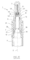
- FIG. 2 differs from that described previously with reference to FIG. 1 by the shape of the application element holder 5 and by that of the cap 10.
- the tubular portion 28 of the applicator element holder 5 is identical to that of Figure 1 for the portion that extends under the collar 29 but has above the latter a frustoconical portion 70 and a cylindrical portion 71 connecting to the part 34.
- the cylindrical portion 71 has a height greater than that of the skirt 25, such that the applicator holder 5 protrudes further from the adapter 4 than in the embodiment previously described, which can facilitate the application, the case applicable.
- the plug 10 of the example of FIG. 2 comprises an outer skirt 47 same as that of Figure 1, but the inner skirt 48 has in the upper part an annular lip 73 elastically deformable which is applied against the outer surface 74 of the cylindrical portion 71, substantially at its connection to the portion 34.
- the lip 73 can scrape the applicator holder 5 each time the cap 10 is removed, which can reduce the risk of soiling.
- the lip 73 applying sealingly on the element holder 5, can reduce the volume of the housing 58 of the cap 10 containing the application element 7, and reduce the risk that the product will flow to the collar 29.
- the capsule 12 contributes in the example of Figure 2 to the sealing of the closure of the container and comprises for this purpose a skirt 76 which is engaged so waterproof on the inner skirt 48.
- FIG. 3 differs from that of FIG. form of the adapter 4, by that of the plug 10, as well as by the nature of the element 7, which is in the example considered a flocked tip.
- the plug 10 comprises firstly a body 11 which is made for example in the body 11 being closed at the top and having in the lower part a annular groove 80 and secondly an outer tubular skirt 81.
- the latter comprises a boss 83 snapped into the annular groove 80, being threaded internally for screw on an externally threaded skirt 85 of the adapter 4, this skirt 85 replacing the Internally threaded skirt of the examples of Figures 1 and 2.
- the body 11 has a bottom portion which is sealingly applied against the tubular portion 28 above the collar 29.
- FIG. 4 differs from that of FIG. only by the shape of the plug 10 and by the nature of the applicator element 7.
- the plug 10 is monolithic, being made by example of a single piece of transparent plastic or glass.
- the cap 10 comprises a neck 43 arranged on the one hand to screw on the skirt 25 threaded internally of the adapter 4, and secondly to apply sealingly against the part tubular 28.
- FIG. 5 shows the adapter of FIG. distinguished from the example of this figure by the fact that the outer skirt 81 is connected superior to an inner skirt 90, whose lower end 91 is located axially above the threaded portion engaged on the skirt 85.
- the relief 83 has been removed.
- the body 11 is engaged in the inner skirt 90 and has a shoulder 93 which abuts against the lower end 91 of the skirt 90.
- the body 11 is applied by its slice lower against the flange 29 and also applies against the tubular portion 28. It is for example made in a transparent material or not, while the outer skirt 81 is made of an opaque material.
- the upper part 96 of the body 11 constitutes a window to see the application element 7 and, where appropriate, to observe the product color in the case of a deposit of it against the inner surface of the body 11.
- FIG. 6 comprises a plug 10 having a structure rather close to that shown in Figure 1.
- the adapter 4 has, as in the example of FIG. 1, the skirts 20 for mounting and receiving the plug 10, the skirt 25 being extended superiorly by a rim 98 whose inner diameter is slightly greater than the outer diameter of the skirt 47.
- the adapter 4 further comprises an annular lip 99 forming with the flange 98 an annular groove 100 whose role is to improve ergonomics, aesthetics and ease of demolding.
- the applicator of FIG. 6 comprises several supply channels 40 of the application element 7 in product.
- These channels 40 comprise portions 103 which cross part 34 and which open into spaces 104 formed between legs 105, the latter having as can be seen in FIG. 7 in particular, an outer surface 106 extending obliquely to the application element 7.
- the number of legs 105 is for example between 2 and 8.
- FIG. 8 comprises an adapter 4 whose skirt 20 is arranged to screw on the neck 13 of the container body 3.
- the wall transverse 22 comprises a small annular lip 110 arranged to be applied on the upper edge of the collar 13.
- the skirt 25 of the adapter 4 is similar to that of the example of FIG.
- the plug 10 comprises a body 11 monolithic whose neck 43 has an external thread arranged to screw into the skirt 25.
- the application element holder 5 is made in one piece with the adapter 4, as can also be seen in Figure 9.
- the tubular portion 28 of the applicator element holder 5 is connected to the wall 22.
- the application element 7 is powered by a plurality of channels 40 which are angularly equidistant around the X axis and opening through orifices 115, as can be seen in FIG. 10, between tabs 116 which extend along the skirt 36, around and slightly above it.
- These legs 116 present to their end a surface 118 inclined downward towards the mouth of the housing 8, as it can be seen in Figure 10 in particular.
- This surface 118 facilitates the flow of the produced on the outer periphery of the application element and avoids the formation of a drop of product when using inclined.
- Surface 118 may facilitate the flow of the produced on the periphery of the application element 7.
- Figure 11 differs from that of Figure 8 essentially by the presence on the holder of application element 5 of an annular lip sealing 112 which diverges upwards.
- This lip 112 is arranged to apply, substantially at the height of the base of the portion 34, on the plug 10, when it is in place on the container.
- the lip 112 limits the internal volume of the cap.
- the application element 7 can be received in a housing 8 which can be defined by a portion 34 formed integrally by molding with the whole of the element-holder 5, as is particularly the case of the example shown in FIG. 1, or defined by an insert, as is the case in particular with the example of the figure 12.
- the application element holder 5 comprises inner fins 122 for fixing the portion 34 in the element holder 5. This fixation is made by tightening but could alternatively be carried out by snapping or otherwise.
- a tubular wall 125 can extend along a portion of the length of the applicator element 7 at the end of the application element holder 5.
- feeding the application element product is made through two diametrically opposed channels 126 and 127 formed between the part 34 and the application element holder 5 substantially at the base of the tubular wall 125.
- the latter makes it possible to ensure a more homogeneous distribution of the product around the application element 7.
- the channels 126 and 127 open into the annular space formed between the upper end 131 of the portion 34 and the tubular wall 125 and the element 7 and the tubular wall 125.
- the tubular wall 125 is connected at its base to a wall substantially frustoconical portion 130 of the applicator element, which converges towards the distal end of the application element 7.
- the number of channels could be different, and one could have for example more than two evenly distributed channels around the X axis.
- Part 34 can be made with a different shape and in particular a recessed form, this portion 34 may be at the limit not be thicker than the skirt 36, particularly when a method of fixing the application element other than stapling is used and it is not necessary that the bottom of the housing 8 is reinforced.
- the supply channel or channels 40 of the application element 7 can be made still otherwise, and in particular be non-parallel to the X axis.
- the bottom of the housing 8 can communicate through a passage with the inside of the container.
- the cap can be fixed on the holder application element and the latter attach to the container body.
- the container body is replaced by a container equipped with a pump or a valve, and the adapter can be connected to the body of container so as to act on a pump or valve stem.
Landscapes
- Engineering & Computer Science (AREA)
- Mechanical Engineering (AREA)
- Closures For Containers (AREA)
- Coating Apparatus (AREA)
- Containers And Packaging Bodies Having A Special Means To Remove Contents (AREA)
- Media Introduction/Drainage Providing Device (AREA)
Applications Claiming Priority (2)
| Application Number | Priority Date | Filing Date | Title |
|---|---|---|---|
| FR0450117 | 2004-01-22 | ||
| FR0450117A FR2865360B1 (fr) | 2004-01-22 | 2004-01-22 | Applicateur comportant un element d'application solidaire, lors de l'utilisation, d'un recipient contenant un produit a appliquer |
Publications (2)
| Publication Number | Publication Date |
|---|---|
| EP1557111A1 true EP1557111A1 (de) | 2005-07-27 |
| EP1557111B1 EP1557111B1 (de) | 2010-12-08 |
Family
ID=34630692
Family Applications (1)
| Application Number | Title | Priority Date | Filing Date |
|---|---|---|---|
| EP05300052A Expired - Lifetime EP1557111B1 (de) | 2004-01-22 | 2005-01-21 | Applikator mit einem Auftragselement, welcher mit einem Produktbehälter verbunden ist |
Country Status (10)
| Country | Link |
|---|---|
| US (1) | US8075215B2 (de) |
| EP (1) | EP1557111B1 (de) |
| JP (1) | JP2005246051A (de) |
| KR (1) | KR100577966B1 (de) |
| CN (1) | CN100496330C (de) |
| AT (1) | ATE490705T1 (de) |
| BR (1) | BRPI0500103A (de) |
| DE (1) | DE602005025171D1 (de) |
| ES (1) | ES2357444T3 (de) |
| FR (1) | FR2865360B1 (de) |
Cited By (3)
| Publication number | Priority date | Publication date | Assignee | Title |
|---|---|---|---|---|
| FR2950256A1 (fr) * | 2009-09-21 | 2011-03-25 | Ko Chuan Wei | Accumulateur a double etancheite pour distributeur de parfum |
| US7950865B2 (en) | 2006-03-21 | 2011-05-31 | L'oreal | Packaging and applicator device |
| FR3022316A1 (fr) * | 2014-06-11 | 2015-12-18 | Oreal | Systeme de connexion etanche, applicateur d'un produit cosmetique et procede de montage associe |
Families Citing this family (24)
| Publication number | Priority date | Publication date | Assignee | Title |
|---|---|---|---|---|
| WO2007042061A1 (de) * | 2005-10-12 | 2007-04-19 | Schwan-Stabilo Cosmetics Gmbh & Co. Kg | Dip-applikator |
| JP5241104B2 (ja) * | 2007-01-12 | 2013-07-17 | 小林製薬株式会社 | 外用組成物 |
| JP5486296B2 (ja) * | 2009-12-25 | 2014-05-07 | 花王株式会社 | 塗布具 |
| CN102452090A (zh) * | 2010-10-28 | 2012-05-16 | 吉列公司 | 个人护理瓶 |
| WO2014022420A1 (en) | 2012-07-30 | 2014-02-06 | Sashay Beauty Products, Inc. | Pen dispensers with cartridges and interchangeable tip applicators |
| CN105636637A (zh) * | 2013-08-21 | 2016-06-01 | 威瑞卡制药公司 | 用于治疗皮肤病症的组合物、方法和系统 |
| CA2971279C (en) | 2014-12-17 | 2023-09-19 | Matthew Davidson | Commercially viable synthesis of cantharidin and bioactive cantharidin derivatives |
| EP3247996A4 (de) | 2015-01-20 | 2019-01-02 | Verrica Pharmaceuticals, Inc. | Quantifizierung und herstellung von kantharidin in pharmazeutischer qualität |
| WO2017163237A1 (en) * | 2016-03-22 | 2017-09-28 | Meticx Technologies Ltd | Nail polish capsule |
| FR3053225B1 (fr) * | 2016-06-29 | 2020-11-13 | Lvmh Rech | Dispositif applicateur de produit cosmetique |
| JP6759876B2 (ja) * | 2016-09-02 | 2020-09-23 | セイコーエプソン株式会社 | ボトルセット、ボトル |
| FR3057744B1 (fr) * | 2016-10-24 | 2018-12-07 | L'oreal | Applicateur de produit cosmetique et procede d'application associe |
| KR20190122220A (ko) * | 2017-02-17 | 2019-10-29 | 포렉스 코포레이션 | 액체 도포기 및 장치 |
| AU2018281313B2 (en) | 2017-06-06 | 2024-05-02 | Verrica Pharmaceuticals Inc. | Treatment of cutaneous disorders |
| USD900312S1 (en) | 2017-06-15 | 2020-10-27 | Verrica Pharmaceuticals, Inc. | Applicator |
| EP3638356A1 (de) | 2017-06-15 | 2020-04-22 | Verrica Pharmaceuticals, Inc. | Vorrichtungen und verfahren zur behandlung von erkrankungen der körperoberfläche |
| KR102765631B1 (ko) | 2017-10-04 | 2025-02-11 | 베리카 파마슈티컬스 인크. | 칸타리딘의 합성 |
| CN108720258B (zh) * | 2018-05-30 | 2024-03-22 | 中山阿蓓亚软管有限公司 | 一种用于涂抹液体唇膏的唇刷 |
| CN108619613B (zh) * | 2018-05-31 | 2022-07-12 | 河南医学高等专科学校 | 一种皮肤科涂药装置 |
| CN108543211B (zh) * | 2018-05-31 | 2021-12-07 | 常远 | 一种皮肤科药膏涂抹器 |
| CN112533509B (zh) * | 2019-07-16 | 2022-12-06 | 深圳市德昌裕塑胶制品有限公司 | 包装容器 |
| US11259624B2 (en) * | 2019-10-30 | 2022-03-01 | Masoud Tabesh Nekoo | Paint applicator with brush |
| US11772851B2 (en) | 2021-06-21 | 2023-10-03 | Medmix Switzerland Ag | Liquid applicator |
| JP7651172B2 (ja) | 2021-08-06 | 2025-03-26 | 大成化工株式会社 | 薬液塗布具、およびそれを備える薬液塗布容器 |
Citations (12)
| Publication number | Priority date | Publication date | Assignee | Title |
|---|---|---|---|---|
| US64732A (en) | 1867-05-14 | wylie | ||
| US158943A (en) | 1875-01-19 | Improvement in brushes | ||
| FR940464A (fr) | 1947-01-31 | 1948-12-14 | Pinceau réservoir à remplissage et écoulement automatiques pour récipients contenant des produits liquides, semi-liquides ou agglutinants | |
| DE3122237A1 (de) | 1981-06-04 | 1983-01-05 | Hartmut 7500 Karlsruhe Klocke | Verpackung fuer fluessiges fuellgut |
| FR2585934A1 (fr) | 1985-08-09 | 1987-02-13 | Oreal | Dispositif applicateur d'un produit liquide, notamment de vernis a ongles |
| DE3608955A1 (de) | 1986-03-18 | 1987-10-08 | Schwan Stabilo Schwanhaeusser | Auftragsgeraet |
| US4990016A (en) | 1988-12-16 | 1991-02-05 | David Seidler | Liquid applicator sampler tube |
| US5339841A (en) * | 1992-01-24 | 1994-08-23 | L'oreal | Makeup device |
| US5345981A (en) | 1992-09-24 | 1994-09-13 | Stanford Pavenick | Applicator for fluid products |
| US5397195A (en) * | 1993-06-25 | 1995-03-14 | L'oreal | Assembly for the dispensing and the application of a fluid product |
| WO2001076408A1 (en) * | 2000-03-31 | 2001-10-18 | Cornelis Van Buuren | Device for dispensing a fluid |
| US6536977B1 (en) * | 2000-08-09 | 2003-03-25 | Marsha Hammel | Dispenser for shaving cream |
Family Cites Families (11)
| Publication number | Priority date | Publication date | Assignee | Title |
|---|---|---|---|---|
| US2253779A (en) * | 1940-03-13 | 1941-08-26 | Gutierrez Julian | Fountain applicator |
| DE1027104B (de) * | 1955-12-29 | 1958-03-27 | Deutsche Bundesbahn | Fuellschreiber |
| GB1006221A (en) * | 1963-11-21 | 1965-09-29 | Bernard Frederick Krauth | Improvements in or relating to liquid dispensers |
| US3655290A (en) * | 1970-10-02 | 1972-04-11 | Griffith & Associates Inc | Applicator instrument |
| BE789917A (fr) | 1972-06-12 | 1973-04-11 | Pfizer | Pinceau applicateur |
| GB1502942A (en) * | 1974-03-06 | 1978-03-08 | Gavia Ag | Liquid dispenser |
| US4040753A (en) * | 1976-07-15 | 1977-08-09 | Griffith, Inc. | Applicator instrument |
| FR2599230B2 (fr) * | 1985-08-09 | 1991-08-23 | Oreal | Dispositif applicateur d'un produit liquide, notamment de vernis a ongles. |
| US4748990A (en) * | 1986-05-28 | 1988-06-07 | Avon Products, Inc. | Cosmetic applicator |
| US6536971B1 (en) * | 2001-08-31 | 2003-03-25 | Carrand Companies, Inc. | Contoured wash mit assembly |
| US6969210B1 (en) * | 2003-10-23 | 2005-11-29 | Newell Robert L | Multi-lumen applicator implements and application method |
-
2004
- 2004-01-22 FR FR0450117A patent/FR2865360B1/fr not_active Expired - Fee Related
-
2005
- 2005-01-21 EP EP05300052A patent/EP1557111B1/de not_active Expired - Lifetime
- 2005-01-21 US US11/038,234 patent/US8075215B2/en not_active Expired - Fee Related
- 2005-01-21 AT AT05300052T patent/ATE490705T1/de not_active IP Right Cessation
- 2005-01-21 ES ES05300052T patent/ES2357444T3/es not_active Expired - Lifetime
- 2005-01-21 BR BR0500103-0A patent/BRPI0500103A/pt not_active Application Discontinuation
- 2005-01-21 CN CNB2005100026017A patent/CN100496330C/zh not_active Expired - Fee Related
- 2005-01-21 DE DE602005025171T patent/DE602005025171D1/de not_active Expired - Lifetime
- 2005-01-22 KR KR1020050006056A patent/KR100577966B1/ko not_active Expired - Fee Related
- 2005-01-24 JP JP2005015568A patent/JP2005246051A/ja not_active Withdrawn
Patent Citations (12)
| Publication number | Priority date | Publication date | Assignee | Title |
|---|---|---|---|---|
| US64732A (en) | 1867-05-14 | wylie | ||
| US158943A (en) | 1875-01-19 | Improvement in brushes | ||
| FR940464A (fr) | 1947-01-31 | 1948-12-14 | Pinceau réservoir à remplissage et écoulement automatiques pour récipients contenant des produits liquides, semi-liquides ou agglutinants | |
| DE3122237A1 (de) | 1981-06-04 | 1983-01-05 | Hartmut 7500 Karlsruhe Klocke | Verpackung fuer fluessiges fuellgut |
| FR2585934A1 (fr) | 1985-08-09 | 1987-02-13 | Oreal | Dispositif applicateur d'un produit liquide, notamment de vernis a ongles |
| DE3608955A1 (de) | 1986-03-18 | 1987-10-08 | Schwan Stabilo Schwanhaeusser | Auftragsgeraet |
| US4990016A (en) | 1988-12-16 | 1991-02-05 | David Seidler | Liquid applicator sampler tube |
| US5339841A (en) * | 1992-01-24 | 1994-08-23 | L'oreal | Makeup device |
| US5345981A (en) | 1992-09-24 | 1994-09-13 | Stanford Pavenick | Applicator for fluid products |
| US5397195A (en) * | 1993-06-25 | 1995-03-14 | L'oreal | Assembly for the dispensing and the application of a fluid product |
| WO2001076408A1 (en) * | 2000-03-31 | 2001-10-18 | Cornelis Van Buuren | Device for dispensing a fluid |
| US6536977B1 (en) * | 2000-08-09 | 2003-03-25 | Marsha Hammel | Dispenser for shaving cream |
Cited By (3)
| Publication number | Priority date | Publication date | Assignee | Title |
|---|---|---|---|---|
| US7950865B2 (en) | 2006-03-21 | 2011-05-31 | L'oreal | Packaging and applicator device |
| FR2950256A1 (fr) * | 2009-09-21 | 2011-03-25 | Ko Chuan Wei | Accumulateur a double etancheite pour distributeur de parfum |
| FR3022316A1 (fr) * | 2014-06-11 | 2015-12-18 | Oreal | Systeme de connexion etanche, applicateur d'un produit cosmetique et procede de montage associe |
Also Published As
| Publication number | Publication date |
|---|---|
| FR2865360B1 (fr) | 2006-05-26 |
| ATE490705T1 (de) | 2010-12-15 |
| EP1557111B1 (de) | 2010-12-08 |
| ES2357444T3 (es) | 2011-04-26 |
| CN100496330C (zh) | 2009-06-10 |
| US8075215B2 (en) | 2011-12-13 |
| US20050169696A1 (en) | 2005-08-04 |
| DE602005025171D1 (de) | 2011-01-20 |
| CN1644130A (zh) | 2005-07-27 |
| FR2865360A1 (fr) | 2005-07-29 |
| BRPI0500103A (pt) | 2005-08-23 |
| JP2005246051A (ja) | 2005-09-15 |
| KR100577966B1 (ko) | 2006-05-11 |
| KR20050076775A (ko) | 2005-07-27 |
Similar Documents
| Publication | Publication Date | Title |
|---|---|---|
| EP1557111B1 (de) | Applikator mit einem Auftragselement, welcher mit einem Produktbehälter verbunden ist | |
| EP0549780B1 (de) | Vorrichtung zum auftragen von flüssigkeiten, insbesondere von kosmetischen produkten | |
| EP1195103B1 (de) | Auftragegerät und Behälter mit einem solchen Auftragegerät | |
| EP1481607B2 (de) | Vorrichtung zum Aufbewahren und Auftragen eines Produktes mit einem Abstreifelement | |
| EP1726236B1 (de) | Applikator und Vorrichtung zum Applizieren eines kosmetischen Produktes | |
| FR2765859A1 (fr) | Dispositif pour le conditionnement de deux composants | |
| EP0839735A1 (de) | Schwenkbare Verschlusskappe mit verbessertem Verbindungselement | |
| FR3085256A1 (fr) | Applicateur pour l'application d'un produit, notamment d'un produit cosmetique | |
| FR3016274A1 (fr) | Dispositif d'essorage avec levre d'essuyage a geometrie variable | |
| EP1869995A1 (de) | Einheit zur Verpackung und Applikation eines Produkts, insbesondere eines Kosmetikprodukts, und entsprechendes Applikationsverfahren | |
| EP1842448B1 (de) | Vorrichtung zum Aufbewahren und Auftragen | |
| EP1174355A1 (de) | Vorrichtung zum Aufbewahren und Ausgeben eines kapillaren Produktes | |
| FR2949446A1 (fr) | Recipient comprenant un reservoir pour produit liquide, dispositif comprenant un tel recipient et utilisation d'un tel dispositif pour appliquer sur une surface le produit contenu dans le reservoir | |
| EP1614367B1 (de) | Vorrichtung zum Aufbewahren und zum Auftragen eines Produktes | |
| FR2951918A1 (fr) | Applicateur comportant une liaison permettant d'incliner la surface d'application | |
| EP1797789B1 (de) | Applikator mit Vorratsbehälter, im besonderen für den Nagellack | |
| FR2964022A1 (fr) | Essoreur pour applicateur de produit, ensemble d'application comprenant un tel essoreur, et son utilisation en cosmetique | |
| FR2882505A1 (fr) | Tube distributeur de produits cremeux | |
| FR2926446A1 (fr) | Applicateur pour la reception et l'application d'un produit, notamment d'un produit cosmetique, du type a cuillere | |
| EP0764410B1 (de) | Auftrageeinheit für Nagellack | |
| FR2867957A1 (fr) | Dispositif de conditionnement et d'application d'un produit, notamment cosmetique | |
| FR2864431A1 (fr) | Distributeur d'un produit cosmetique fluide | |
| EP1759609B1 (de) | Applikator mit Zähnen | |
| EP1621102B1 (de) | Vorrichtung zum Aufbewahren und Auftragen | |
| FR2876557A1 (fr) | Stylo distributeur d'un produit cosmetique fluide |
Legal Events
| Date | Code | Title | Description |
|---|---|---|---|
| PUAI | Public reference made under article 153(3) epc to a published international application that has entered the european phase |
Free format text: ORIGINAL CODE: 0009012 |
|
| 17P | Request for examination filed |
Effective date: 20050121 |
|
| AK | Designated contracting states |
Kind code of ref document: A1 Designated state(s): AT BE BG CH CY CZ DE DK EE ES FI FR GB GR HU IE IS IT LI LT LU MC NL PL PT RO SE SI SK TR |
|
| AX | Request for extension of the european patent |
Extension state: AL BA HR LV MK YU |
|
| AKX | Designation fees paid |
Designated state(s): AT BE BG CH CY CZ DE DK EE ES FI FR GB GR HU IE IS IT LI LT LU MC NL PL PT RO SE SI SK TR |
|
| 17Q | First examination report despatched |
Effective date: 20061218 |
|
| GRAP | Despatch of communication of intention to grant a patent |
Free format text: ORIGINAL CODE: EPIDOSNIGR1 |
|
| GRAS | Grant fee paid |
Free format text: ORIGINAL CODE: EPIDOSNIGR3 |
|
| GRAA | (expected) grant |
Free format text: ORIGINAL CODE: 0009210 |
|
| AK | Designated contracting states |
Kind code of ref document: B1 Designated state(s): AT BE BG CH CY CZ DE DK EE ES FI FR GB GR HU IE IS IT LI LT LU MC NL PL PT RO SE SI SK TR |
|
| REG | Reference to a national code |
Ref country code: GB Ref legal event code: FG4D Free format text: NOT ENGLISH |
|
| REG | Reference to a national code |
Ref country code: CH Ref legal event code: EP |
|
| REG | Reference to a national code |
Ref country code: IE Ref legal event code: FG4D |
|
| REF | Corresponds to: |
Ref document number: 602005025171 Country of ref document: DE Date of ref document: 20110120 Kind code of ref document: P |
|
| REG | Reference to a national code |
Ref country code: NL Ref legal event code: VDEP Effective date: 20101208 |
|
| REG | Reference to a national code |
Ref country code: ES Ref legal event code: FG2A Ref document number: 2357444 Country of ref document: ES Kind code of ref document: T3 Effective date: 20110426 |
|
| PG25 | Lapsed in a contracting state [announced via postgrant information from national office to epo] |
Ref country code: LT Free format text: LAPSE BECAUSE OF FAILURE TO SUBMIT A TRANSLATION OF THE DESCRIPTION OR TO PAY THE FEE WITHIN THE PRESCRIBED TIME-LIMIT Effective date: 20101208 |
|
| LTIE | Lt: invalidation of european patent or patent extension |
Effective date: 20101208 |
|
| PG25 | Lapsed in a contracting state [announced via postgrant information from national office to epo] |
Ref country code: AT Free format text: LAPSE BECAUSE OF FAILURE TO SUBMIT A TRANSLATION OF THE DESCRIPTION OR TO PAY THE FEE WITHIN THE PRESCRIBED TIME-LIMIT Effective date: 20101208 Ref country code: SI Free format text: LAPSE BECAUSE OF FAILURE TO SUBMIT A TRANSLATION OF THE DESCRIPTION OR TO PAY THE FEE WITHIN THE PRESCRIBED TIME-LIMIT Effective date: 20101208 Ref country code: BG Free format text: LAPSE BECAUSE OF FAILURE TO SUBMIT A TRANSLATION OF THE DESCRIPTION OR TO PAY THE FEE WITHIN THE PRESCRIBED TIME-LIMIT Effective date: 20110308 Ref country code: CY Free format text: LAPSE BECAUSE OF FAILURE TO SUBMIT A TRANSLATION OF THE DESCRIPTION OR TO PAY THE FEE WITHIN THE PRESCRIBED TIME-LIMIT Effective date: 20101208 Ref country code: SE Free format text: LAPSE BECAUSE OF FAILURE TO SUBMIT A TRANSLATION OF THE DESCRIPTION OR TO PAY THE FEE WITHIN THE PRESCRIBED TIME-LIMIT Effective date: 20101208 Ref country code: NL Free format text: LAPSE BECAUSE OF FAILURE TO SUBMIT A TRANSLATION OF THE DESCRIPTION OR TO PAY THE FEE WITHIN THE PRESCRIBED TIME-LIMIT Effective date: 20101208 Ref country code: FI Free format text: LAPSE BECAUSE OF FAILURE TO SUBMIT A TRANSLATION OF THE DESCRIPTION OR TO PAY THE FEE WITHIN THE PRESCRIBED TIME-LIMIT Effective date: 20101208 |
|
| REG | Reference to a national code |
Ref country code: IE Ref legal event code: FD4D |
|
| PG25 | Lapsed in a contracting state [announced via postgrant information from national office to epo] |
Ref country code: IE Free format text: LAPSE BECAUSE OF FAILURE TO SUBMIT A TRANSLATION OF THE DESCRIPTION OR TO PAY THE FEE WITHIN THE PRESCRIBED TIME-LIMIT Effective date: 20101208 Ref country code: EE Free format text: LAPSE BECAUSE OF FAILURE TO SUBMIT A TRANSLATION OF THE DESCRIPTION OR TO PAY THE FEE WITHIN THE PRESCRIBED TIME-LIMIT Effective date: 20101208 Ref country code: GR Free format text: LAPSE BECAUSE OF FAILURE TO SUBMIT A TRANSLATION OF THE DESCRIPTION OR TO PAY THE FEE WITHIN THE PRESCRIBED TIME-LIMIT Effective date: 20110309 Ref country code: PT Free format text: LAPSE BECAUSE OF FAILURE TO SUBMIT A TRANSLATION OF THE DESCRIPTION OR TO PAY THE FEE WITHIN THE PRESCRIBED TIME-LIMIT Effective date: 20110408 Ref country code: CZ Free format text: LAPSE BECAUSE OF FAILURE TO SUBMIT A TRANSLATION OF THE DESCRIPTION OR TO PAY THE FEE WITHIN THE PRESCRIBED TIME-LIMIT Effective date: 20101208 Ref country code: IS Free format text: LAPSE BECAUSE OF FAILURE TO SUBMIT A TRANSLATION OF THE DESCRIPTION OR TO PAY THE FEE WITHIN THE PRESCRIBED TIME-LIMIT Effective date: 20110408 |
|
| BERE | Be: lapsed |
Owner name: L'OREAL Effective date: 20110131 |
|
| PG25 | Lapsed in a contracting state [announced via postgrant information from national office to epo] |
Ref country code: SK Free format text: LAPSE BECAUSE OF FAILURE TO SUBMIT A TRANSLATION OF THE DESCRIPTION OR TO PAY THE FEE WITHIN THE PRESCRIBED TIME-LIMIT Effective date: 20101208 Ref country code: MC Free format text: LAPSE BECAUSE OF NON-PAYMENT OF DUE FEES Effective date: 20110131 Ref country code: RO Free format text: LAPSE BECAUSE OF FAILURE TO SUBMIT A TRANSLATION OF THE DESCRIPTION OR TO PAY THE FEE WITHIN THE PRESCRIBED TIME-LIMIT Effective date: 20101208 Ref country code: PL Free format text: LAPSE BECAUSE OF FAILURE TO SUBMIT A TRANSLATION OF THE DESCRIPTION OR TO PAY THE FEE WITHIN THE PRESCRIBED TIME-LIMIT Effective date: 20101208 |
|
| REG | Reference to a national code |
Ref country code: CH Ref legal event code: PL |
|
| PLBE | No opposition filed within time limit |
Free format text: ORIGINAL CODE: 0009261 |
|
| STAA | Information on the status of an ep patent application or granted ep patent |
Free format text: STATUS: NO OPPOSITION FILED WITHIN TIME LIMIT |
|
| PG25 | Lapsed in a contracting state [announced via postgrant information from national office to epo] |
Ref country code: DK Free format text: LAPSE BECAUSE OF FAILURE TO SUBMIT A TRANSLATION OF THE DESCRIPTION OR TO PAY THE FEE WITHIN THE PRESCRIBED TIME-LIMIT Effective date: 20101208 Ref country code: LI Free format text: LAPSE BECAUSE OF NON-PAYMENT OF DUE FEES Effective date: 20110131 Ref country code: CH Free format text: LAPSE BECAUSE OF NON-PAYMENT OF DUE FEES Effective date: 20110131 |
|
| 26N | No opposition filed |
Effective date: 20110909 |
|
| PG25 | Lapsed in a contracting state [announced via postgrant information from national office to epo] |
Ref country code: BE Free format text: LAPSE BECAUSE OF NON-PAYMENT OF DUE FEES Effective date: 20110131 |
|
| REG | Reference to a national code |
Ref country code: DE Ref legal event code: R097 Ref document number: 602005025171 Country of ref document: DE Effective date: 20110909 |
|
| PG25 | Lapsed in a contracting state [announced via postgrant information from national office to epo] |
Ref country code: LU Free format text: LAPSE BECAUSE OF NON-PAYMENT OF DUE FEES Effective date: 20110121 |
|
| PG25 | Lapsed in a contracting state [announced via postgrant information from national office to epo] |
Ref country code: TR Free format text: LAPSE BECAUSE OF FAILURE TO SUBMIT A TRANSLATION OF THE DESCRIPTION OR TO PAY THE FEE WITHIN THE PRESCRIBED TIME-LIMIT Effective date: 20101208 |
|
| PG25 | Lapsed in a contracting state [announced via postgrant information from national office to epo] |
Ref country code: HU Free format text: LAPSE BECAUSE OF FAILURE TO SUBMIT A TRANSLATION OF THE DESCRIPTION OR TO PAY THE FEE WITHIN THE PRESCRIBED TIME-LIMIT Effective date: 20101208 |
|
| REG | Reference to a national code |
Ref country code: FR Ref legal event code: PLFP Year of fee payment: 11 |
|
| PGFP | Annual fee paid to national office [announced via postgrant information from national office to epo] |
Ref country code: ES Payment date: 20141211 Year of fee payment: 11 |
|
| PGFP | Annual fee paid to national office [announced via postgrant information from national office to epo] |
Ref country code: IT Payment date: 20150115 Year of fee payment: 11 Ref country code: DE Payment date: 20150113 Year of fee payment: 11 |
|
| PGFP | Annual fee paid to national office [announced via postgrant information from national office to epo] |
Ref country code: FR Payment date: 20150108 Year of fee payment: 11 Ref country code: GB Payment date: 20150121 Year of fee payment: 11 |
|
| REG | Reference to a national code |
Ref country code: DE Ref legal event code: R119 Ref document number: 602005025171 Country of ref document: DE |
|
| GBPC | Gb: european patent ceased through non-payment of renewal fee |
Effective date: 20160121 |
|
| REG | Reference to a national code |
Ref country code: FR Ref legal event code: ST Effective date: 20160930 |
|
| PG25 | Lapsed in a contracting state [announced via postgrant information from national office to epo] |
Ref country code: DE Free format text: LAPSE BECAUSE OF NON-PAYMENT OF DUE FEES Effective date: 20160802 Ref country code: GB Free format text: LAPSE BECAUSE OF NON-PAYMENT OF DUE FEES Effective date: 20160121 |
|
| PG25 | Lapsed in a contracting state [announced via postgrant information from national office to epo] |
Ref country code: FR Free format text: LAPSE BECAUSE OF NON-PAYMENT OF DUE FEES Effective date: 20160201 |
|
| PG25 | Lapsed in a contracting state [announced via postgrant information from national office to epo] |
Ref country code: IT Free format text: LAPSE BECAUSE OF NON-PAYMENT OF DUE FEES Effective date: 20160121 |
|
| REG | Reference to a national code |
Ref country code: ES Ref legal event code: FD2A Effective date: 20170224 |
|
| PG25 | Lapsed in a contracting state [announced via postgrant information from national office to epo] |
Ref country code: ES Free format text: LAPSE BECAUSE OF NON-PAYMENT OF DUE FEES Effective date: 20160122 |