EP1557189A1 - Appareil d'injection - Google Patents
Appareil d'injection Download PDFInfo
- Publication number
- EP1557189A1 EP1557189A1 EP05007617A EP05007617A EP1557189A1 EP 1557189 A1 EP1557189 A1 EP 1557189A1 EP 05007617 A EP05007617 A EP 05007617A EP 05007617 A EP05007617 A EP 05007617A EP 1557189 A1 EP1557189 A1 EP 1557189A1
- Authority
- EP
- European Patent Office
- Prior art keywords
- cartridge
- injection
- plunger
- guide member
- clutch
- Prior art date
- Legal status (The legal status is an assumption and is not a legal conclusion. Google has not performed a legal analysis and makes no representation as to the accuracy of the status listed.)
- Granted
Links
Images











Classifications
-
- A—HUMAN NECESSITIES
- A61—MEDICAL OR VETERINARY SCIENCE; HYGIENE
- A61M—DEVICES FOR INTRODUCING MEDIA INTO, OR ONTO, THE BODY; DEVICES FOR TRANSDUCING BODY MEDIA OR FOR TAKING MEDIA FROM THE BODY; DEVICES FOR PRODUCING OR ENDING SLEEP OR STUPOR
- A61M5/00—Devices for bringing media into the body in a subcutaneous, intra-vascular or intramuscular way; Accessories therefor, e.g. filling or cleaning devices, arm rests
- A61M5/178—Syringes
- A61M5/20—Automatic syringes, e.g. with automatically actuated piston rod, with automatic needle injection, filling automatically
-
- A—HUMAN NECESSITIES
- A61—MEDICAL OR VETERINARY SCIENCE; HYGIENE
- A61M—DEVICES FOR INTRODUCING MEDIA INTO, OR ONTO, THE BODY; DEVICES FOR TRANSDUCING BODY MEDIA OR FOR TAKING MEDIA FROM THE BODY; DEVICES FOR PRODUCING OR ENDING SLEEP OR STUPOR
- A61M5/00—Devices for bringing media into the body in a subcutaneous, intra-vascular or intramuscular way; Accessories therefor, e.g. filling or cleaning devices, arm rests
- A61M5/178—Syringes
- A61M5/24—Ampoule syringes, i.e. syringes with needle for use in combination with replaceable ampoules or cartridges, e.g. automatic
-
- A—HUMAN NECESSITIES
- A61—MEDICAL OR VETERINARY SCIENCE; HYGIENE
- A61M—DEVICES FOR INTRODUCING MEDIA INTO, OR ONTO, THE BODY; DEVICES FOR TRANSDUCING BODY MEDIA OR FOR TAKING MEDIA FROM THE BODY; DEVICES FOR PRODUCING OR ENDING SLEEP OR STUPOR
- A61M5/00—Devices for bringing media into the body in a subcutaneous, intra-vascular or intramuscular way; Accessories therefor, e.g. filling or cleaning devices, arm rests
- A61M5/178—Syringes
- A61M5/31—Details
- A61M5/315—Pistons; Piston-rods; Guiding, blocking or restricting the movement of the rod or piston; Appliances on the rod for facilitating dosing ; Dosing mechanisms
- A61M5/31533—Dosing mechanisms, i.e. setting a dose
- A61M5/31545—Setting modes for dosing
- A61M5/31548—Mechanically operated dose setting member
- A61M5/3155—Mechanically operated dose setting member by rotational movement of dose setting member, e.g. during setting or filling of a syringe
- A61M5/31553—Mechanically operated dose setting member by rotational movement of dose setting member, e.g. during setting or filling of a syringe without axial movement of dose setting member
-
- A—HUMAN NECESSITIES
- A61—MEDICAL OR VETERINARY SCIENCE; HYGIENE
- A61M—DEVICES FOR INTRODUCING MEDIA INTO, OR ONTO, THE BODY; DEVICES FOR TRANSDUCING BODY MEDIA OR FOR TAKING MEDIA FROM THE BODY; DEVICES FOR PRODUCING OR ENDING SLEEP OR STUPOR
- A61M5/00—Devices for bringing media into the body in a subcutaneous, intra-vascular or intramuscular way; Accessories therefor, e.g. filling or cleaning devices, arm rests
- A61M5/178—Syringes
- A61M5/31—Details
- A61M5/315—Pistons; Piston-rods; Guiding, blocking or restricting the movement of the rod or piston; Appliances on the rod for facilitating dosing ; Dosing mechanisms
- A61M5/31533—Dosing mechanisms, i.e. setting a dose
- A61M5/31545—Setting modes for dosing
- A61M5/31548—Mechanically operated dose setting member
- A61M5/31555—Mechanically operated dose setting member by purely axial movement of dose setting member, e.g. during setting or filling of a syringe
-
- A—HUMAN NECESSITIES
- A61—MEDICAL OR VETERINARY SCIENCE; HYGIENE
- A61M—DEVICES FOR INTRODUCING MEDIA INTO, OR ONTO, THE BODY; DEVICES FOR TRANSDUCING BODY MEDIA OR FOR TAKING MEDIA FROM THE BODY; DEVICES FOR PRODUCING OR ENDING SLEEP OR STUPOR
- A61M5/00—Devices for bringing media into the body in a subcutaneous, intra-vascular or intramuscular way; Accessories therefor, e.g. filling or cleaning devices, arm rests
- A61M5/178—Syringes
- A61M5/31—Details
- A61M5/315—Pistons; Piston-rods; Guiding, blocking or restricting the movement of the rod or piston; Appliances on the rod for facilitating dosing ; Dosing mechanisms
- A61M5/31565—Administration mechanisms, i.e. constructional features, modes of administering a dose
- A61M5/31576—Constructional features; Drive mechanisms or modes for piston rods
- A61M5/31578—Constructional features; Drive mechanisms or modes for piston rods the piston rod being moved by the axial movement of a component directly in contact with it
-
- A—HUMAN NECESSITIES
- A61—MEDICAL OR VETERINARY SCIENCE; HYGIENE
- A61M—DEVICES FOR INTRODUCING MEDIA INTO, OR ONTO, THE BODY; DEVICES FOR TRANSDUCING BODY MEDIA OR FOR TAKING MEDIA FROM THE BODY; DEVICES FOR PRODUCING OR ENDING SLEEP OR STUPOR
- A61M5/00—Devices for bringing media into the body in a subcutaneous, intra-vascular or intramuscular way; Accessories therefor, e.g. filling or cleaning devices, arm rests
- A61M5/178—Syringes
- A61M5/24—Ampoule syringes, i.e. syringes with needle for use in combination with replaceable ampoules or cartridges, e.g. automatic
- A61M2005/2403—Ampoule inserted into the ampoule holder
- A61M2005/2407—Ampoule inserted into the ampoule holder from the rear
-
- A—HUMAN NECESSITIES
- A61—MEDICAL OR VETERINARY SCIENCE; HYGIENE
- A61M—DEVICES FOR INTRODUCING MEDIA INTO, OR ONTO, THE BODY; DEVICES FOR TRANSDUCING BODY MEDIA OR FOR TAKING MEDIA FROM THE BODY; DEVICES FOR PRODUCING OR ENDING SLEEP OR STUPOR
- A61M5/00—Devices for bringing media into the body in a subcutaneous, intra-vascular or intramuscular way; Accessories therefor, e.g. filling or cleaning devices, arm rests
- A61M5/178—Syringes
- A61M5/24—Ampoule syringes, i.e. syringes with needle for use in combination with replaceable ampoules or cartridges, e.g. automatic
- A61M2005/2418—Ampoule syringes, i.e. syringes with needle for use in combination with replaceable ampoules or cartridges, e.g. automatic comprising means for damping shocks on ampoule
-
- A—HUMAN NECESSITIES
- A61—MEDICAL OR VETERINARY SCIENCE; HYGIENE
- A61M—DEVICES FOR INTRODUCING MEDIA INTO, OR ONTO, THE BODY; DEVICES FOR TRANSDUCING BODY MEDIA OR FOR TAKING MEDIA FROM THE BODY; DEVICES FOR PRODUCING OR ENDING SLEEP OR STUPOR
- A61M5/00—Devices for bringing media into the body in a subcutaneous, intra-vascular or intramuscular way; Accessories therefor, e.g. filling or cleaning devices, arm rests
- A61M5/178—Syringes
- A61M5/24—Ampoule syringes, i.e. syringes with needle for use in combination with replaceable ampoules or cartridges, e.g. automatic
- A61M2005/2485—Ampoule holder connected to rest of syringe
- A61M2005/2488—Ampoule holder connected to rest of syringe via rotation, e.g. threads or bayonet
-
- A—HUMAN NECESSITIES
- A61—MEDICAL OR VETERINARY SCIENCE; HYGIENE
- A61M—DEVICES FOR INTRODUCING MEDIA INTO, OR ONTO, THE BODY; DEVICES FOR TRANSDUCING BODY MEDIA OR FOR TAKING MEDIA FROM THE BODY; DEVICES FOR PRODUCING OR ENDING SLEEP OR STUPOR
- A61M5/00—Devices for bringing media into the body in a subcutaneous, intra-vascular or intramuscular way; Accessories therefor, e.g. filling or cleaning devices, arm rests
- A61M5/178—Syringes
- A61M5/31—Details
- A61M2005/3125—Display means, e.g. to indicate dose setting
-
- A—HUMAN NECESSITIES
- A61—MEDICAL OR VETERINARY SCIENCE; HYGIENE
- A61M—DEVICES FOR INTRODUCING MEDIA INTO, OR ONTO, THE BODY; DEVICES FOR TRANSDUCING BODY MEDIA OR FOR TAKING MEDIA FROM THE BODY; DEVICES FOR PRODUCING OR ENDING SLEEP OR STUPOR
- A61M5/00—Devices for bringing media into the body in a subcutaneous, intra-vascular or intramuscular way; Accessories therefor, e.g. filling or cleaning devices, arm rests
- A61M5/178—Syringes
- A61M5/31—Details
- A61M2005/3125—Display means, e.g. to indicate dose setting
- A61M2005/3126—Display means, e.g. to indicate dose setting related to dosing
-
- A—HUMAN NECESSITIES
- A61—MEDICAL OR VETERINARY SCIENCE; HYGIENE
- A61M—DEVICES FOR INTRODUCING MEDIA INTO, OR ONTO, THE BODY; DEVICES FOR TRANSDUCING BODY MEDIA OR FOR TAKING MEDIA FROM THE BODY; DEVICES FOR PRODUCING OR ENDING SLEEP OR STUPOR
- A61M2205/00—General characteristics of the apparatus
- A61M2205/58—Means for facilitating use, e.g. by people with impaired vision
- A61M2205/581—Means for facilitating use, e.g. by people with impaired vision by audible feedback
-
- A—HUMAN NECESSITIES
- A61—MEDICAL OR VETERINARY SCIENCE; HYGIENE
- A61M—DEVICES FOR INTRODUCING MEDIA INTO, OR ONTO, THE BODY; DEVICES FOR TRANSDUCING BODY MEDIA OR FOR TAKING MEDIA FROM THE BODY; DEVICES FOR PRODUCING OR ENDING SLEEP OR STUPOR
- A61M2205/00—General characteristics of the apparatus
- A61M2205/58—Means for facilitating use, e.g. by people with impaired vision
- A61M2205/583—Means for facilitating use, e.g. by people with impaired vision by visual feedback
- A61M2205/585—Means for facilitating use, e.g. by people with impaired vision by visual feedback having magnification means, e.g. magnifying glasses
-
- A—HUMAN NECESSITIES
- A61—MEDICAL OR VETERINARY SCIENCE; HYGIENE
- A61M—DEVICES FOR INTRODUCING MEDIA INTO, OR ONTO, THE BODY; DEVICES FOR TRANSDUCING BODY MEDIA OR FOR TAKING MEDIA FROM THE BODY; DEVICES FOR PRODUCING OR ENDING SLEEP OR STUPOR
- A61M5/00—Devices for bringing media into the body in a subcutaneous, intra-vascular or intramuscular way; Accessories therefor, e.g. filling or cleaning devices, arm rests
- A61M5/178—Syringes
- A61M5/20—Automatic syringes, e.g. with automatically actuated piston rod, with automatic needle injection, filling automatically
- A61M5/206—Automatic syringes, e.g. with automatically actuated piston rod, with automatic needle injection, filling automatically with automatic needle insertion
-
- A—HUMAN NECESSITIES
- A61—MEDICAL OR VETERINARY SCIENCE; HYGIENE
- A61M—DEVICES FOR INTRODUCING MEDIA INTO, OR ONTO, THE BODY; DEVICES FOR TRANSDUCING BODY MEDIA OR FOR TAKING MEDIA FROM THE BODY; DEVICES FOR PRODUCING OR ENDING SLEEP OR STUPOR
- A61M5/00—Devices for bringing media into the body in a subcutaneous, intra-vascular or intramuscular way; Accessories therefor, e.g. filling or cleaning devices, arm rests
- A61M5/178—Syringes
- A61M5/31—Details
- A61M5/315—Pistons; Piston-rods; Guiding, blocking or restricting the movement of the rod or piston; Appliances on the rod for facilitating dosing ; Dosing mechanisms
- A61M5/31533—Dosing mechanisms, i.e. setting a dose
- A61M5/31535—Means improving security or handling thereof, e.g. blocking means, means preventing insufficient dosing, means allowing correction of overset dose
-
- A—HUMAN NECESSITIES
- A61—MEDICAL OR VETERINARY SCIENCE; HYGIENE
- A61M—DEVICES FOR INTRODUCING MEDIA INTO, OR ONTO, THE BODY; DEVICES FOR TRANSDUCING BODY MEDIA OR FOR TAKING MEDIA FROM THE BODY; DEVICES FOR PRODUCING OR ENDING SLEEP OR STUPOR
- A61M5/00—Devices for bringing media into the body in a subcutaneous, intra-vascular or intramuscular way; Accessories therefor, e.g. filling or cleaning devices, arm rests
- A61M5/178—Syringes
- A61M5/31—Details
- A61M5/315—Pistons; Piston-rods; Guiding, blocking or restricting the movement of the rod or piston; Appliances on the rod for facilitating dosing ; Dosing mechanisms
- A61M5/31533—Dosing mechanisms, i.e. setting a dose
- A61M5/31535—Means improving security or handling thereof, e.g. blocking means, means preventing insufficient dosing, means allowing correction of overset dose
- A61M5/31543—Means improving security or handling thereof, e.g. blocking means, means preventing insufficient dosing, means allowing correction of overset dose piston rod reset means, i.e. means for causing or facilitating retraction of piston rod to its starting position during cartridge change
-
- A—HUMAN NECESSITIES
- A61—MEDICAL OR VETERINARY SCIENCE; HYGIENE
- A61M—DEVICES FOR INTRODUCING MEDIA INTO, OR ONTO, THE BODY; DEVICES FOR TRANSDUCING BODY MEDIA OR FOR TAKING MEDIA FROM THE BODY; DEVICES FOR PRODUCING OR ENDING SLEEP OR STUPOR
- A61M5/00—Devices for bringing media into the body in a subcutaneous, intra-vascular or intramuscular way; Accessories therefor, e.g. filling or cleaning devices, arm rests
- A61M5/178—Syringes
- A61M5/31—Details
- A61M5/315—Pistons; Piston-rods; Guiding, blocking or restricting the movement of the rod or piston; Appliances on the rod for facilitating dosing ; Dosing mechanisms
- A61M5/31533—Dosing mechanisms, i.e. setting a dose
- A61M5/31545—Setting modes for dosing
- A61M5/31548—Mechanically operated dose setting member
- A61M5/3156—Mechanically operated dose setting member using volume steps only adjustable in discrete intervals, i.e. individually distinct intervals
-
- A—HUMAN NECESSITIES
- A61—MEDICAL OR VETERINARY SCIENCE; HYGIENE
- A61M—DEVICES FOR INTRODUCING MEDIA INTO, OR ONTO, THE BODY; DEVICES FOR TRANSDUCING BODY MEDIA OR FOR TAKING MEDIA FROM THE BODY; DEVICES FOR PRODUCING OR ENDING SLEEP OR STUPOR
- A61M5/00—Devices for bringing media into the body in a subcutaneous, intra-vascular or intramuscular way; Accessories therefor, e.g. filling or cleaning devices, arm rests
- A61M5/178—Syringes
- A61M5/31—Details
- A61M5/315—Pistons; Piston-rods; Guiding, blocking or restricting the movement of the rod or piston; Appliances on the rod for facilitating dosing ; Dosing mechanisms
- A61M5/31533—Dosing mechanisms, i.e. setting a dose
- A61M5/31545—Setting modes for dosing
- A61M5/31548—Mechanically operated dose setting member
- A61M5/31563—Mechanically operated dose setting member interacting with a displaceable stop member
-
- A—HUMAN NECESSITIES
- A61—MEDICAL OR VETERINARY SCIENCE; HYGIENE
- A61M—DEVICES FOR INTRODUCING MEDIA INTO, OR ONTO, THE BODY; DEVICES FOR TRANSDUCING BODY MEDIA OR FOR TAKING MEDIA FROM THE BODY; DEVICES FOR PRODUCING OR ENDING SLEEP OR STUPOR
- A61M5/00—Devices for bringing media into the body in a subcutaneous, intra-vascular or intramuscular way; Accessories therefor, e.g. filling or cleaning devices, arm rests
- A61M5/178—Syringes
- A61M5/31—Details
- A61M5/315—Pistons; Piston-rods; Guiding, blocking or restricting the movement of the rod or piston; Appliances on the rod for facilitating dosing ; Dosing mechanisms
- A61M5/31565—Administration mechanisms, i.e. constructional features, modes of administering a dose
- A61M5/3159—Dose expelling manners
- A61M5/31593—Multi-dose, i.e. individually set dose repeatedly administered from the same medicament reservoir
Definitions
- the invention relates to an injection device with a container for receiving a Injection liquid containing cartridge, at the proximal end of a Injection needle is attached.
- Such injection device is known from DE 42 23 958 A1. That there illustrated and described injection device works very reliable and precise, is but less suitable for using larger cartridges with larger quantities of injection fluid.
- the im Claim 1 given principle is particularly "foolproof" when it comes to a replace the used cartridge with a new one.
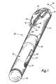
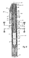
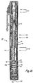
- FIG. 1 shows in schematic form a three-dimensional representation of an injection device according to the invention 30.
- This has at its distal end an adjustment knob 32, which allows rotation in the direction of an arrow 34 dose setting, if the device is in its position shown in FIG. (In the Fig. 1 position, the dose setting is not activated.)
- Button 32 is rotatably mounted in a tubular distal housing part 36 in which there is an elongate detent opening 38 and to which a resilient clip 40 is attached.
- the clip 40 is a magnifying glass 42 for reading the set dose.
- the clip 40 has a radially inwardly projecting projection 44, which serves to trigger an injection and the elongated detent opening 38 is opposite.
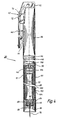
- An annular part 46 closes in the proximal direction to the distal housing part 36 on, which is firmly connected to the housing part 36. This is followed in the proximal direction a middle housing part 48. This is followed in the proximal direction by a proximal Housing part 50 which a cartridge 52 with a liquid to be injected 53 (Fig. 4) receives and is provided with at least one viewing window 54 through which the Filling state of the cartridge 52 can be observed.
- a plurality of small openings 54A is provided as a viewing window used. This has the advantage that the patient does not use his fingers through the window 54 and thereby can slow the movement of the cartridge 52 during puncture, but that the visual observation of the filling state of the cartridge 52 is very possible is.
- a clamping cap for clamping 56, with its external thread 58 in a corresponding internal thread 60 (Fig. 2) of the proximal housing part 50 is screwed to the injection device before an injection to stretch.
- the tightening of the Injection device 30 only possible if a needle 76 is mounted.
- the injection device 30 taut as a needle 76 mounted and the clamping cap 56th is screwed to the stop in the proximal housing part 50.
- the adjustment knob 32 is idle, i. you can turn it in the direction of the arrow 34 ( Figure 1) without setting a dose.
- the dose setting is deactivated here.
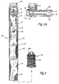
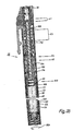
- Fig. 2 shows the injection device 30 after tightening and after unscrewing the clamping cap 56. The latter is unscrewed before an injection in order to prepare the device for injection.
- a tension spring 172 (FIG. 7)
- the latching pin 64 moves somewhat in the proximal direction and bears against the proximal edge of the elongate latching opening 38, cf. FIG. 2.
- a desired injection dose can be set by turning the adjusting knob 32.
- the magnifying glass 42 has two Einzellupen 70, 72. Because of the high number of Dose settings that are possible for injection, in the present case e.g. thirty different settings between "0" and "58" units, the scale is double row the peripheral surface 69 (Fig. 9 and 11) of Dosierknopfs 32 printed. Fig. 2A shows a Settlement 69 'of this peripheral surface 69.
- the scale has a first row 71 with the numbers "0", "4", "8”, etc., and a second row 73 with the numbers "2", “6", "10", "14", etc.
- a Stop 75 marks the zero position.
- the lens 70 magnifies a number from the first one Row 71, and the lens 72 shows an enlarged number from the second row 73, see. Fig. 2.
- This allows an unambiguous reading, i. in Fig. 2 is the set Dose 16 units. (In this example, the dose can always be two units can therefore be adjusted from "0", “2", "4" etc. units to "58" units.)
- a triggering of the injection device 30 is possible. This is done by pressure on the clip 40 in the direction of a force vector 74 (FIG. 1). It will by the radially inwardly projecting projection 44 of the locking pin 64 radially inwardly pressed.
- the tension spring 172 (FIG. 7) then causes a piercing of the injection needle first 76 ( Figure 4), followed by an injection of the adjusted injection dose through the pierced needle 76. This will be described below with reference to FIGS. 24 and 25 described. It is therefore a hidden needle device 76, i. this is for not visible to the patient, and the injection process runs after the triggering fully automatic.
- the device 30 is thus stretched by screwing the clamping cap 56, and it is brought by unscrewing the clamping cap 56 in the position shown in FIG. 2, in which the desired dose can be set and then injected.
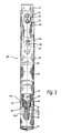
- Fig. 3 shows the injection device 30 in the position shown in FIG. 1, wherein the proximal portion is shown cut away.
- Cartridge 52 is located in a cartridge holder 80, which has a tapered neck 82 at its proximal end and is provided there with an external thread 84.
- the cartridge 52 projects with its neck 86 into this neck 82. It is provided at its proximal end with a rubber membrane 88 which, in use, is pierced by the distal portion 90 of the needle 76.
- the needle 76, 90 is attached to a conventional needle holder 92, which is screwed with its internal thread on the external thread 84 of the cartridge holder 80. It is protected in the tensioned state by the clamping cap 56 and is then not visible.
- FIG. 3 clearly shows, the clamping cap 56 bears against a cylindrical section 56A the needle holder 92 and acts on this in the distal direction.
- the Locking knob 64 in its distal position in the recess 38, as shown in FIGS. 1 and 3 shown, and the adjustment knob 32 is deactivated, as already described.
- the needle holder 92 is missing, and the device 30 can not be tensioned because the cylindrical portion 56A of FIG Clamp 56 now projects into the cavity 98 of the cartridge holder 80, as shown in FIG. 16 shows.
- the detent button 64 is then in the position shown in FIG. 17, in Fig. 3 with 64 'is designated, i. a cocking and an injection are not in this condition possible. This ensures that the injection device 30 without needle 76 is not tensioned can be.
- Cartridge holder 80 has an annular collar 100 and abuts against a damping ring 102 which is supported on an annular shoulder 104 on the inside of proximal housing part 50. This is the proximal end position of the cartridge holder 80.
- a rubber piston 106 In the cartridge 52 is located in the usual way, a rubber piston 106, and this is at an injection, after the insertion of the needle 76, by a plunger 108 in shifted in the proximal direction to those previously set with the knob 32 Squeeze amount of liquid from the cartridge 52.
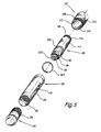
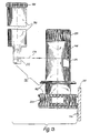
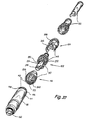
- FIG. 5 shows the various parts of the proximal section of the injection device 30 in an exploded, three-dimensional view.
- the internal thread 60 is provided in the proximal housing part 50 into which the external thread 58 of the clamping cap 56 can be screwed in order to clamp the injection device. It is a coarse thread with trapezoidal thread cross-section.
- the middle housing part 48 has at its proximal end an external thread 109, the for connection to an internal thread 110 at the distal end of the proximal Housing part 50 is used. Also, the middle housing part 48 has at its proximal end on the inside a short axial longitudinal teeth 112, the longitudinal guidance of a Longitudinal rib 111 (or a plurality of longitudinal ribs) on the outside of the cartridge holder 80 serves. These longitudinal ribs 111 cause a rotation of the cartridge holder 80, as long as the injection device 30 is in its ready state. At the Changing a cartridge 52, this longitudinal guide is deactivated, i. then they slide Longitudinal ribs 111 out of the axial longitudinal teeth 112 out, see. below the Fig. 26 to 32. The longitudinal guide through the parts 111, 112 prevents the Cartridge holder 80 when changing an injection needle 76 relative to the housing part 50th rotates and thereby releases from a front adapter part 116 ( Figures 6 and 14).
- the cartridge holder 80 has at its distal end an external thread 114, the Connection with an internal thread 115 (FIGS. 6 and 14) of the front adapter part 116 serves.
- the external thread 114 has an interruption 118, which is a special function when changing cartridges. This will be described below.
- the neck 82 of the cartridge holder 80 is formed in the manner of a socket wrench and has a diagonal groove 120, the rotation of the adapter part 116 (see. Fig. 6) allows, if one puts this neck 82 in the adapter part 116, the is formed correspondingly complementary so that it can engage in the groove 120, see. Figs. 14 and 20.
- the parts 120 and 224 thus fit like keys and lock each other.
- needle 76 and cartridge 52 are not shown in order not to view the illustration overloaded with many details.
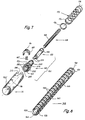
- Figs. 6 to 9 show in exploded, three-dimensional representation of the remaining Parts of the injection device 30.
- the representation is partly highly schematic to the To facilitate understanding of the invention.
- Fig. 9 is compared to Figs. 6 and 7 in one enlarged scale to better represent the details.
- the front adapter part 116 with its internal thread 115 is followed by a rear adapter part 122 which is rotatably but axially non-displaceably connected to the front, proximal adapter part 116 during assembly, wherein a torque-dependent clutch (K7 in Fig. 18) is provided.
- a torque-dependent clutch K7 in Fig. 18
- a guide part 124 which serves for the axial guidance of the plunger 108 (FIGS. 7 & 8), and that during assembly with the rear adapter part 122 rotatably, but axially slidably connected.
- a stop ring 126 whose function will be explained below and in an annular groove 262 of the rear adapter part 122nd is mounted.
- the distal housing part 36 takes an inner tube 130 in that shown in Fig. 6 Rotary position on, i. a longitudinal slot 136 of the inner tube 130 is aligned with the Locking recess 38 of the housing part 36.
- the inner tube 130 forms on a short part its longitudinal extent the visible in Fig. 1 annular part 46, which has a Protrusion 133 has as anti-rotation, which in a corresponding recess 133 'of the Housing part 36 protrudes.
- the inner tube 130 with a External thread 132 provided for connection to an internal thread 133 (Fig. 5) on distal end of the middle housing part 48 is used.
- the inner tube 130 is on a part its length is provided with an internal axial toothing 134.
- the inner tube 130 has two in the region of its distal end Lateral recesses 138, 140 for locking with corresponding barbs 142nd to a molding 144 shown in Figs. 9 and 10, which is used i.a. the clip 40 carries.
- Fig. 7 shows right next to the distal housing part 36, the front part 148 and the rear part 150 of a so-called feed sleeve 151, which serves for dose adjustment, ie as adjusting.
- the parts 148 and 150 are firmly connected to each other during assembly by snapping and then form the Zustellhülse 151. This is rotated at the dose setting and thereby displaces the plunger 108 which engages in the mounted state with its external thread 159 in an internal thread 152 of the part 148 , in the proximal direction.
- the part 148 leads in an annular groove 153 a support part 155, which carries the locking pin 64 and is pressed radially outwards by a compression spring 157, cf. Fig. 7.
- Fig. 8 shows the plunger 108 on an enlarged scale. Its external thread 159 is a rectangular steep thread.
- the plunger 108 has two longitudinal grooves 156, 158. In the assembled state engages in the longitudinal groove 156 a serving as an engaging member projection 160 (FIG. 6) of the guide member 124 and thereby prevents rotation of the plunger 108 relative to the housing during dose setting and injection of the injection device 30.
- a micro-toothing 162 is approximately as at a rack.
- the gearing 162 extends from the proximal end 164 to about to a stop 166 in the groove 158, here about two-thirds of the longitudinal extent of the plunger 108.
- a stop 166 in the groove 158, here about two-thirds of the longitudinal extent of the plunger 108.
- Fig. 7 is denoted by 172, the tension spring, which is the energy for an injection stores and with its proximal end 174 in the assembled state via a sliding disk 176 is supported on the part 148 and this applied in the proximal direction.
- the tension spring which is the energy for an injection stores and with its proximal end 174 in the assembled state via a sliding disk 176 is supported on the part 148 and this applied in the proximal direction.
- the spring 172 With its distal end 178, the spring 172 is supported on an annular shoulder 180 of the shaped piece 144 (FIG. 9) .
- the latter consists of an elastic plastic and has a resilient locking member 182 with a locking projection 184 which engages in the dose setting in an axial longitudinal toothing 220 (Fig. 7) of the part 148 and causes the rotation of the part 148 clicks. These allow blind patients to set the desired dose by counting the clicking sounds.
- the locking projection 184 holds after the dose adjustment by engagement with the spline 220, the part 148 in the adjusted position, so acts like a clutch (K3 in Fig. 18), which is released in the course of an injection.
- the magnifying glass 42 is shown only schematically in FIG. 9. She gets into one from below Recess 186 of the fitting 144 used. This is symbolic through a dash-dotted line indicated 188.
- a return spring for the adjusting knob 32 is designated. This is a Torsion spring. Your distal end 192 is rotatably connected to the knob 32, you proximal end 194 with fitting 144. This spring 190 rotates after an injection the adjustment knob 32 back to its zero position in the through the magnifying glass 42, the dose "0" is readable.
- the adjusting knob 32 has on its inside a spline 196, which with a corresponding axial toothing 198 of the part 150 of the feed sleeve 151 cooperates.
- Figure 9 is drawn on a larger scale than Figure 7).
- a Opening 199 (FIG. 11) at the distal end of the adjusting knob 32 is replaced by a lid 200 (FIGS. 9 and 35).
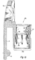
- Fig.10 shows the fitting 144 in longitudinal section. Its right part 202 is almost completely inside the distal housing part 36. The latter has a lateral recess 204 (FIG. 7) and through which the clip 40 protrudes outwards, thereby securing the fitting 144 against rotation. Longitudinal ribs 203 are used for low-friction lateral guidance of the spring 172, which is shown in Fig. 7.
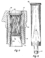
- the adjusting knob 32 in longitudinal section. Its internal axial toothing 196 extends over about two-thirds of the total length of this part. This thus has at the distal end a short portion 206 which has no axial toothing, and it has a longer proximal portion 208, where also no axial toothing is.
- the adjusting knob 32 On its outside, has an annular bead 210 for engagement with a corresponding annular groove 212 (FIG. 6) of the distal housing part 36. It is clipped into this annular groove 212 during assembly. Further, it has an annular space 211 which receives the return spring 190, which is shown in Fig. 9.
- FIG. 12 shows the part 150 of the feed sleeve 151. This has at the proximal end two radially resilient hooks 212 (FIG. 7) for the form-fitting engagement in corresponding recesses 214 of the part 148 of the feed sleeve. This intervention is symbolized by a dot-dash line 216 in FIG.
- the adjusting knob 32 can no torque is transmitted to the part 150. This is the freewheeling position of the Adjustment knob 32, which has been explained in detail in FIGS. 1 and 3.
- the adjustment knob 32 can also no torque transmitted to the part 150. This is the position after one Injection, and in this position, the adjusting knob 32 by the return spring 190 (FIG. 9) turned back to its zero position, so that the next dose setting again at the Position "0" can begin.
- the part 148 has, at its distal end, an outer axial toothing 220 which, in the tensioned state of the device 30, cooperates with the latching projection 184 (FIG. 10) to generate clicking noises during the dose setting and once "set" dose set, ie to prevent unintentional adjustment of this dose.
- the part 148 has an outer axial toothing 222 at its proximal end tensioned state of the device, this axial toothing 222 is not engaged with the inner spline 134 of the inner tube 130 (FIG. 6), so that the parts 148 and 150, which together form the feed sleeve 151, are freely rotatable to the dose to be able to adjust.
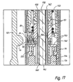
- This state is shown enlarged in Fig. 17 (coupling K4 open; Alternatively, in Fig. 17, the clutch K4 could also be closed to a Twisting of the delivery sleeve 151 by the patient to block).
- member 148 Upon injection, member 148 (together with member 150) shifts more proximally Direction, and thereby comes its axial toothing 222 in engagement with the axial Internal toothing 134 of the inner tube 130, which in Fig. 13 only very schematically is indicated. This position is e.g. shown in Fig. 24 (clutch K4 closed).
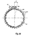
- the Number of teeth of the axial teeth 220 coincides with the number of teeth of axial teeth 222. In the present embodiment, it is ever thirty-two teeth to a total of thirty dose settings from 0 to 58 units too allow, cf. Figures 2A and 36. (Two teeth are not used for dose setting used, cf. Fig. 36 and the accompanying explanations.)
- FIG. 14 shows, in an exploded view, the front adapter part 116 and the rear adapter part 122 on an enlarged scale and in spatial representation.
- the front adapter part 116 has a recess 224 with projections 226, which together serve for connection to the already explained diagonal groove 120 (FIG. 5) of the cartridge holder 80 in order to allow rotation of the front adapter part 116 by means of the cartridge holder 80 turned over. Such a twist may be necessary in unfavorable cases when cartridge change.
- the front adapter part 116 also has two axial plastic springs 228, which according to FIG. 15 in the mounted state against the cartridge 52 and these with a force in act on the proximal direction, cf. also Fig. 20.
- the front adapter part 116 has a resilient tongue 230, which in axial Direction extends and at its free end on the radially inner side of a locking member 232nd (with triangular cross-section) is provided with the corresponding Locking projections 234 of the rear adapter part 122 cooperates and with these a Slip clutch forms, which is effective when changing the cartridge and prevents the Patient when screwing the cartridge holder 80 to the front adapter part 116 a to generates large torque on the front adapter part 116 and this thereby damaged. If the patient is too high torque in the direction of the arrow 236 (FIG. 14) is generated, the locking member 232 slides over the locking projections 234, and the Front adapter part 116 rotates relative to the rear adapter part 122, so that the Injection device can not be damaged.
- a resilient tongue 230 which in axial Direction extends and at its free end on the radially inner side of a locking member 232nd (with triangular cross-section) is provided with the corresponding Locking projections
- annular bead 238 of the front adapter part 116 in an annular groove 240 of the rear Adapter part 122 is engaged, as shown in FIG. 15.
- the annular groove 240 is located two axial projections 252, 254.
- the front adapter part 116 also has a radially inwardly projecting resilient detent member 242, which engages in the recess 118 (FIG. 5) of the cartridge holder 80 provided external thread 114 serves.
- the locking member 242 snaps to one Cartridge change in this recess 118 a.
- the front adapter part 116 is first by turning the Cartridge holder 80 in the direction of arrow 237 (Fig. 14) rotated, because through the Locking member 242 transmit torque from the cartridge holder 80 to the adapter part 116 becomes. This rotational movement serves to return the plunger 108, as the following is described in Figs. 27 to 29.
- the ratchet teeth 234 are on a tubular portion 246 of the rear adapter part 122.
- This section 246 has at its proximal portion a radially resilient portion 248, on its radially inner side with ratchet teeth 250th is provided.
- These serve to engage in the micro-toothing 162 shown in FIG. 8, and the ratchet teeth 250 are therefore substantially complementary to the micro-toothing 162 formed, cf. Fig. 15.
- the axial projections 252, 254 protrude in the proximal direction, and their task is under other, constantly a predetermined distance between the front adapter part 116th and the rear adapter part 122 and the front adapter part 116 rotatably store.
- the radially outer side of the rear adapter part 122 is with an axial External teeth 256 provided, which complementary to the axial internal teeth 134th the inner tube 130 is formed and engages in this, as long as the adapter part 122 located in the inner tube 130.
- the rear adapter part 122 also has on its distal side a tubular extension 260, which in its distal end region with an annular groove 262 is provided, which receives the stop ring 126 shown in Fig. 6.
- the tube-like Extension 260 has shown in FIG. 15 an axially extending aperture 264, through which the projection 160 (see Fig. 6) of the guide member 124 in the one longitudinal groove 156 of the plunger 108 protrudes and the latter thereby rotationally fixed, but axially displaceable, with the guide member 124th combines.
- the guide member 124 has two axial projections 266, 268 which face each other diametrically opposite and protrude in the proximal direction. Because of the ring bulge 238 (FIG. 14) on the front adapter part 116, the inside diameter of the projections 266, 268 increases in its proximal region 266 ', 268' too.
- the projections 266, 268 are guided axially by two approximately to them complementary guide openings 272, 270 of the rear Adapter parts 122, i. between adapter part 122 and guide part 124 is not relative Rotary movement possible, but an axial displacement. The latter is in one Direction limited by the stop ring 126, see. Fig.
- the guide member 124 When injections take place, the guide member 124 is always rotationally fixed, but axially slidably connected to the inner tube 130. When replacing a cartridge is this rotationally fixed connection is canceled, cf. Fig. 26 - 32, and the guide member 124, and the non-rotatably connected parts 108 and 122 can then relative to the housing 36, while the feed sleeve 151 via its external teeth 222 in engagement with the Inner tube 130 is and therefore can not be rotated. This allows a simple Resetting the plunger 108, as described below.
- the guide member 124 On its distal side, the guide member 124 has a tubular extension 276, on the outside of which, according to FIG. 15, an annular groove 278 is provided.
- the proximal part 148 of the delivery sleeve 151 is on its proximal side with a recess 280 provided at the four radially inwardly projecting locking portions 282nd are provided, which in the assembly in the annular groove 278 of the guide member 124th be clipped and thereby the adjusting sleeve 151 rotatable, but axially immovable, connect with the guide part 124.
- Figures 16 and 17 show what happens when the patient attempts to cock the injection device 30 without a needle.
- the proximal opening 98 of the cartridge holder 80 is not covered by the needle holder 92 (FIG. 3), and the portion 56A of the tension knob 56 protrudes through this opening 98 and abuts against the proximal end of the cartridge 52.
- the detent button 64 is not displaced so far in the distal direction that it can engage in the latching opening 38, that is, a tensioning of the device is not possible.
- the present invention makes use of the interaction of various Coupling elements, partly in the form of position-dependent couplings, partly in Form of force-dependent couplings, and of a clutch, the two elements rotatably coupled with each other, but allowed an axial displacement between them.
- FIG. 18 shows these couplings in a schematic overview.
- a position-dependent Clutch K1 whose operation has already been described. It allows one automatically resetting the adjustment knob 72 to "0" in the course of an injection, and so on deactivates the adjustment knob 32 when the device is in its clamping position shown in FIG. 3rd located.
- a force and position-dependent locking coupling K2 is provided between the distal End of the plunger 108 and the distal end of the Zustellhülse 151. This coupling K2 will be described in more detail with reference to FIGS. 28 and 29. She has a role in Replacing the cartridge 52.
- a force and position dependent latching coupling K3 is provided between the housing-fixed locking member 184 and the external axial toothing 220 of the feed sleeve 151st
- This clutch K3 is in engagement when the device is in its cocked position and is used to store the desired dose setting. During an injection, K3 becomes opened, without that the stored information can be lost, because then the Function of the clutch K3 is seamlessly adopted by a clutch K4. (In Fig. 18 is the locking member 184 indicated only by dotted lines to the understanding facilitate.)
- the clutch K4 is a position-dependent clutch, and it is provided between the external axial toothing 222 at the proximal end of the feed sleeve 151 and the axial internal teeth 134 of the inner tube 130.
- the coupling K4 is open, as long as the injection device 30 is in its clamping position, so that there the Zustellhülse 151 can be rotated for dose adjustment.
- a position-dependent clutch K5 is provided between the axial External teeth 274 of the guide member 124 and the axial internal teeth 134 of the Inner tube 130, as well as between the outer axial teeth 256 of the rear Adapter parts 122 and the axial internal teeth 134.
- This coupling K5 is permanent closed as long as the device is ready for injection. It will open when a new one Cartridge 52 is inserted into the device, since in this case the parts 116, 122 and 124 relative to Delivery sleeve 151 must be rotated to bring the plunger 108 in the correct position to be able to.
- An axially displaceable coupling K6 is provided between the projections 266, 268 of the guide member 124 and the rear adapter part 122. This coupling allows the Dose setting, as described below in Fig. 23.
- a slip clutch K7 is provided between the front adapter part 116 and the rear adapter part 122. This is described in more detail in Fig. 14 and is formed by the resilient latch 232 of the front adapter part 116 and the ratchet teeth 234 of the rear adapter part 122. This slip clutch K7 occurs if necessary when changing cartridges Function.
- a force-dependent slip clutch K8 is provided between the rear adapter part 122 and the plunger 108. It is formed by the micro-serration 162 (FIG. 8) of FIG Plunger 108 and the corresponding toothing 250 (Fig. 14) on the rear adapter part 122. It comes into operation in the course of an injection in order to squeeze out Injection liquid 53 from the cartridge 52 to allow, as well as when replacing a cartridge 52.
- a torque-dependent clutch K9 is provided between the Cartridge holder 80 and the front adapter part 116. It is formed by the Recess 118 (Fig. 5) of the external thread 114 and the radially inwardly projecting part 242 (FIG. 14) of the front adapter part 116. This clutch K9 comes into operation when a Cartridge 52 is replaced and ensures that when changing cartridges Tappet 108 is brought into the correct position.
- a position-dependent coupling K10 is provided between the longitudinal ribs 111 of the Cartridge holder 80 and the axial internal teeth 112 of the middle housing part 48th
- the clutch K10 is engaged as long as injections take place and it prevents when changing the injection needle 76 of the cartridge holder 80 relative to the front Adapter part 116 is rotated.
- the clutch K10 will automatically change when the cartridge is replaced opened, since then the cartridge holder 80 is unscrewed from the front adapter part 116 must become.
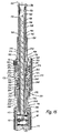
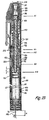
- FIG. 19 again shows the injection device 30 in its position according to FIG. 3, but in a continuous longitudinal section.
- the designation of the parts agrees with the preceding figures, so that reference may be made thereto. It can be seen that during clamping, the projections 266, 268 abut against the front adapter part 116, ie the parts 124, 122, 116 are - after an injection - telescopically completely pushed together, as well as in Figs. 16 and 17. Therefore, they can Transferring clamping force of the clamping cap 56 directly to the spring 172 and press them together until the locking member 64 engages in the recess 38.
- the clutch K1 is opened, i. a dose adjustment is not possible.
- the clutch K2 is opened, i. the plunger 108 is not locked to the part 150.
- the clutch K3 is activated, i. the locking element 184 engages in the longitudinal toothing 220th one.
- the clutch K4 is open, i. the feed sleeve 151 is freely rotatable.
- the clutch K5 is closed, i. the guide member 124 and the rear adapter part 122 are not rotatable relative to the housing 36.
- the clutch K8 is engaged, i. the two adapter parts 116, 122 have the axial follow movements of the plunger 108.
- the clutch K10 is engaged, i. the longitudinal ribs 111 of the cartridge holder 80th are guided by the internal teeth 112 of the middle housing part 48, and thereby the cartridge holder 80 is secured against rotation.
- Fig. 20 is a substantially plan view of the inside of the front adapter part 116 in its assembled state. Reference is made to the explanations of FIG. 14 for the sake of brevity. In particular, it is possible to see the recess 224 which is designed to engage with the socket-like end 120 (FIG. 5) of the cartridge holder 80. The recess 98 of the cartridge holder 80 has a diameter which allows the plunger 108 to push through it.
- Fig. 21 shows how the parts 252, 254, 266 and 268 interdigitate.
- the parts 266, 268 serve, as already described, to non-rotatably connect the parts 122, 124 with each other, but to make them axially displaceable relative to each other, as shown particularly clearly in FIG.
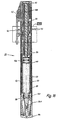
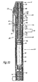
- Fig. 22 shows the injection device in the position shown in FIG. 2 and in longitudinal section.
- the patient has unscrewed the tension cap 56 ( Figure 2) from the thread 60, and the tensioned spring 172 has displaced the internal portions of the device approximately 2 mm in the proximal direction, thereby locking the detent button 64 against the proximal end the recess 38 abuts.
- the Zustellhülse 151 can by Turn the adjusting knob 32 to be rotated to the desired injection dose adjust.
- the clutch K3 is still engaged, i. the latch 184 engages in the Longitudinal toothing 220 a.
- the clutch K4 is not engaged, i. the delivery sleeve is for dose adjustment rotatable relative to the housing.
- the clutch K5 is engaged, i. the guide member 124, the rear adapter part 122, and the plunger 108 can not rotate relative to the housing 36.
- the clutch K8 is engaged, i. the rear adapter part 122 is connected to the plunger 108 and the cartridge holder 80 also coupled in the axial direction, so that these parts in axial direction can only move together.
- the clutch K10 is also engaged.
- the proximal tip of the injection needle 76 in this case has the distance Z from proximal end of the housing part 50. This is the maximum distance, and by the Dose setting it is reduced, as described below in Fig. 23.
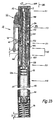
- adjusting knob 32 is rotated clockwise (arrow 300 in Fig. 23), as viewed in the direction of an arrow 302, that is seen in the proximal direction.
- the clutch K4 is open, i. the feed sleeve 151 can rotate freely.
- the clutch K5 is closed, i. the guide member 124 and the rear adapter part 122 are prevented from rotating relative to the housing part 36.
- the injection device 30 After setting the dose to be injected, the injection device 30 is now ready for a Injection.
- the set dose Y remains stored because the clutch K3 rotation the Zustellhülse 151 prevents.
- the patient places the device on the body part, where an injection should be made, e.g. on the buttocks, and then press as shown in FIG. 24 with a symbolically indicated force F on the clip 40, so that this deflected inward is pressed and with its projection 44, the locking knob 64 inward, so that the tensioned injection spring 172 moves the feed sleeve 151 in the proximal direction.
- the detent button 64 slides in the axial longitudinal groove 136 (FIG. 6) of the inner tube 130.
- the clutch K1 initially remains closed.
- the clutch K3 opens, as the axial toothing 220 slides out of the locking member 184.
- the feed sleeve 151 causes via its internal thread 152 an axial Displacement of the plunger 108 in the proximal direction. Since this over the clutch K8 with the rear adapter part 122 is connected, this is also in the axial direction moves, and with it the front adapter part 116 and the cartridge holder 80, so that as shown in FIG. 24, the needle 76 is inserted into the patient. So this is the process piercing the needle 76.
- the clutch K5 remains closed, i. the guide member 124 can be relatively do not turn to the housing part 36.
- the guide member 124 is in direct Drive connection with the feed sleeve 151, so that the guide member 124 in is moved in the proximal direction, but it can not turn and also - about its engagement member 160 - prevents rotation of the plunger 108.
- Cartridge holder 80 becomes so far in the proximal direction during the puncture procedure shifted until its annular collar 100 abuts against the damping ring 102, which at the Ring shoulder 104 is supported. This stops the movement of the cartridge holder 80 in FIG proximal direction.
- the coupling K10 remains constantly engaged, in Fig. 24 the axial internal teeth 112 of the central housing part 48 only with the distal End portion of the longitudinal ribs 111 is engaged, as shown in Fig. 24.
- Fig. 25 shows the further course of an injection. Since the collar 100 is in abutment against the damping ring 102, the cartridge holder 80 can not move further in the proximal direction, and thereby the clutch K8 is released, ie the teeth 250 of the part 248 ( Figure 14) now slide over the micro-toothing 162 (FIG. 8) of the plunger 108, so that this - regardless of the cartridge holder 80 - moves further in the proximal direction, thereby displacing the piston 106 in the cartridge 52 by the set path Y and so from the needle 76 set by the patient Dose of the drug 53 squeezes, which is symbolically indicated in Fig. 25 at 304.
- the feed sleeve 151 slides with its axial external toothing 198 out of the axial internal teeth 196 of the adjustment knob 32, i. the coupling K1 opens. Therefore, the torsion spring 190 can the adjustment knob 32 in its zero position Turn back, which is symbolized in Fig. 25 by the rotation arrow 310.
- the inner parts of the injection device 30 become Telescopically pushed together by a certain path Y to which they were previously at Setting the dose (Fig. 23) were moved apart.
- the clutches K4 and K5 are engaged.
- the clutch K8 is during the Opening phase of an injection opened, but then immediately back into engagement.
- the Clutch K10 remains constantly engaged.
- the coupling K5 is formed here by the fact that the distal end of the external toothing 274 (FIG. 6) of the guide part 124 with the proximal end region of the internal toothing 134 is engaged. About the guide member 124, the plunger 108 against rotation secured (part 160 of the guide member 124).
- the device After the injection, the patient pulls the needle 76 out of the tissue, changing it if necessary a new needle, and then unscrew the clamping cap 56, so that the device 30 again assumes the state of FIG. 3 and 19. In this condition, the device may e.g. be transported in a case or a handbag. Unless with the device insulin a refrigerated storage (refrigerator) is desirable.
- a refrigerated storage refrigerator
- the proximal housing part 50 When replacing a cartridge, the proximal housing part 50 is unscrewed from the unstressed injection device 30, as shown in FIG . This is symbolized in FIG. 23 by a rotation arrow 312.
- FIG. 27 shows the injection device after unscrewing the proximal housing part 50.
- the cartridge holder 80 can now be rotated in the direction of a rotation arrow 317, ie in the counterclockwise direction, as seen in the direction of an arrow 315.
- the plunger 108 can no longer move distally, and consequently the parts 116, 122 and 124 can not rotate, so now the clutch K9 dissolved and the cartridge holder 80 is unscrewed from the front adapter part 116.
- FIGS. 28 and 29 This state is shown in FIGS. 28 and 29.
- the plunger 108 is parked in the interior of the housing 36, 48, and its distal end 168 is via the local annular groove 170 in latching engagement with a radially inwardly projecting collar 322 of the part 150th Die Detent coupling K2 is thus engaged in this state and holds the plunger 108 firmly.
- the cartridge holder 80 with the new cartridge 52 is screwed back onto the front adapter part 116. Seen in the distal direction 315, the cartridge holder 80 is rotated clockwise for this purpose. Since the latching coupling K2 is closed as shown in FIG. 29, the plunger 108 initially can not move in the proximal direction, whereby a rotational movement of the guide member 124, the rear adapter part 122 and the front adapter part 116 is blocked, so that the cartridge holder 80 fully in the front adapter part 116 is screwed in until the latching coupling K9 comes into engagement there. Only then is the locking torque K2 released by the torque generated by the user, and the plunger 108 is displaced in the proximal direction until it gently abuts against the piston 106.
- the piston 106 can not in her move. If the user forcibly tries to move the cartridge holder 80 in the direction of Turning the turning arrow 321 (Fig. 32) continues, the clutch K7 comes into action, i. the Pawl 232 (Fig. 14) slides over the ratchet teeth 234. The user can thus in this Case, the injection device 30 also by using force does not damage, because at Exceeding a predetermined torque in this direction of rotation, the clutch K7 causes the front adapter part 116 to become free relative to the rear adapter part 122 can turn. The clutch K7 thus acts in the direction just described as Slip clutch. In the opposite direction this is not necessary, because in this direction the Cartridge holder 80 is unscrewed from the front adapter part 116.
- the slip clutch K7 prevents the patient by a too large torque Rubber piston 106 elastically compressed. This would have the consequence that in Fig. 33 after screwing the needle 76 (Fig. 3) from this needle injection liquid 53rd would squirt out, which is undesirable. The clutch K7 prevents this.
- the proximal housing part 50 is now screwed on (rotary arrow 324), whereby the coupling K10 is closed, and the injection device 30 is then in a position similar to FIG. 25 and is again ready for use, ie there are no further adjustments - or test procedures necessary. If air bubbles are present in the cartridge 52, they can be removed by injecting a small injection dose upwards into the air. This is shown to the patient while teaching in the hospital.
- the device can after insertion of an injection needle 76 by screwing the Clamp 56 are clamped and is then in a transportable Status.
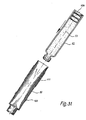
- Fig. 34 shows a variant in which a plurality of small holes 54A is used as the viewing window. This is the preferred solution within the scope of the invention, because the patient can not reach through these holes 54A and therefore can not brake the course of an injection with their fingers.
- Fig. 35 shows the injection apparatus of Fig. 34 from above, but with respect to Fig. 34 on a larger scale.
- FIG. 36 shows a schematic representation of the axial toothing 220 of the infeed sleeve 151 (FIG. 7), and of the latching member 184 (FIG. 8), which engages in this toothing 220 in the course of dose setting.
- the dose settings from zero to "58" are given by way of example.
- the number of thirty-two teeth will be the same for the splines 112, 134, 196, 198, 220, 222, 256 and 274 used to allow the parts of the injection device 30 slide easily into each other and apart. These gears have off For this reason, the same angular position relative to each other, so no "Phase shift".
- the penetration depth U (FIG. 25) of the needle 76 also remains unchanged in the normal case. (Of course, a stitch depth adjustment can be used to the stitch depth to adapt to the patient).
- the proportion Y for the displacement of the piston 106th is used.
- This proportion Y is determined before injection by the parts 124 and 122 are shifted apart at the dose setting by this path Y, cf. Fig. 23, whereby the needle 76 - even before the injection - by this way Y in the proximal Direction is shifted.
- the path of the needle 76 in one injection is thus about the path Y. shorter than L, as explained in FIGS. 22 and 23.
- the axial internal toothing 134 ( Figure 6) is approximately the length L because it guides the guide 124 throughout the entire path L must secure against rotation.
- the guide member 124 is with his gearing 274 just with the distal end in engagement with the Internal teeth 134, as shown in FIGS. 25 and 39, and before the start of an injection you have According to FIGS. 22 and 38, the situation that the axial toothing 222 of the feed sleeve 151 is just before the intervention in the internal teeth 134, which is why the teeth 274 of the immediately adjacent guide member 124 fully with the internal teeth 134 in Intervention is, cf. FIGS. 22 and 38.
- Fig. 37 illustrates once again the couplings that act on cartridge replacement.
- a detachable Connection (external thread 114, internal thread 115), which may also be used as a bayonet lock or the like could be trained.
- the coupling K7 ensures when closing the container 80 that the plunger 108 only gently against the piston 106 is brought and this is not deformed elastically.
- Clutch K6 protrusions 266, 268 and recesses 270, 272. It allows one Adjustment of the axial distance between the parts 122, 124 and the transmission of a Torque between them.
- couplings K7 and K9 e.g. when using a Bayonet closure for the container 80 (in place of the threads 114, 115).
- the user may choose the proximal end 120 of the Use container 80 as a socket wrench to engage the front adapter part 116 to turn in its part 226.
- FIGS. 38 to 40 show different possible positions of the couplings K4 in synoptic terms and K5.
- the device is tensioned and - at the dose setting zero - ready for triggering.
- the Clutch K4 is not engaged.
- the clutch K5 is engaged.
- the border between Delivery sleeve 151 and guide member 124 is located at the point A, namely at the distal End of the internal teeth 134.
- Fig. 39 the injection is completed.
- the locking member 64 has covered the path L.
- the boundary between the parts 151 and 124 has moved to the point B, which is of the Point A has the distance L.
- the point B is located above the lower end of the Spline 134, i. the latter is longer than L, so that in Fig. 39, the clutch K5 can remain closed, i. the distal part of the spline 274 remains engaged with the internal teeth 134.
- the coupling K4 is engaged during the injection.
- Fig. 40 shows the state when the cartridge is changed. Said boundary between the parts 151 and 124 has moved to the point C.
- the clutch K4 is still closed, ie the part 151 can not rotate, and the clutch K5 is opened in order to be able to rotate the guide part 124 during cartridge replacement, as already described in detail.
- the distance from A to C corresponds approximately to the axial length of the internal toothing 134 and is greater than L.
- couplings can be used be, e.g. Couplings using magnets. If the device is e.g. of a Microprocessor or microcontroller is controlled, couplings can be controlled by electrical Energy is pressed.
Landscapes
- Health & Medical Sciences (AREA)
- Vascular Medicine (AREA)
- Engineering & Computer Science (AREA)
- Anesthesiology (AREA)
- Biomedical Technology (AREA)
- Heart & Thoracic Surgery (AREA)
- Hematology (AREA)
- Life Sciences & Earth Sciences (AREA)
- Animal Behavior & Ethology (AREA)
- General Health & Medical Sciences (AREA)
- Public Health (AREA)
- Veterinary Medicine (AREA)
- Infusion, Injection, And Reservoir Apparatuses (AREA)
- Polarising Elements (AREA)
- Injection Moulding Of Plastics Or The Like (AREA)
- Chemical Or Physical Treatment Of Fibers (AREA)
Applications Claiming Priority (6)
| Application Number | Priority Date | Filing Date | Title |
|---|---|---|---|
| DE29900482U | 1999-01-14 | ||
| DE29900482U DE29900482U1 (de) | 1999-01-14 | 1999-01-14 | Injektionsgerät |
| DE29907880U DE29907880U1 (de) | 1999-01-14 | 1999-05-04 | Injektionsgerät mit auswechselbarer Kartusche |
| DE29907881U | 1999-05-04 | ||
| DE29907881U DE29907881U1 (de) | 1999-01-14 | 1999-05-04 | Injektionsgerät |
| EP00906193A EP1140260B1 (fr) | 1999-01-14 | 2000-01-13 | Appareil d'injection |
Related Parent Applications (2)
| Application Number | Title | Priority Date | Filing Date |
|---|---|---|---|
| EP00906193A Division EP1140260B1 (fr) | 1999-01-14 | 2000-01-13 | Appareil d'injection |
| EP00906193.8 Division | 2000-01-13 |
Publications (2)
| Publication Number | Publication Date |
|---|---|
| EP1557189A1 true EP1557189A1 (fr) | 2005-07-27 |
| EP1557189B1 EP1557189B1 (fr) | 2006-05-17 |
Family
ID=41228339
Family Applications (2)
| Application Number | Title | Priority Date | Filing Date |
|---|---|---|---|
| EP05007617A Expired - Lifetime EP1557189B1 (fr) | 1999-01-14 | 2000-01-13 | Appareil d'injection |
| EP00906193A Revoked EP1140260B1 (fr) | 1999-01-14 | 2000-01-13 | Appareil d'injection |
Family Applications After (1)
| Application Number | Title | Priority Date | Filing Date |
|---|---|---|---|
| EP00906193A Revoked EP1140260B1 (fr) | 1999-01-14 | 2000-01-13 | Appareil d'injection |
Country Status (5)
| Country | Link |
|---|---|
| EP (2) | EP1557189B1 (fr) |
| AT (2) | ATE301486T1 (fr) |
| CA (1) | CA2359375A1 (fr) |
| DE (5) | DE29900482U1 (fr) |
| WO (1) | WO2000041754A1 (fr) |
Cited By (12)
| Publication number | Priority date | Publication date | Assignee | Title |
|---|---|---|---|---|
| WO2008037801A1 (fr) * | 2006-09-29 | 2008-04-03 | Novo Nordisk A/S | Dispositif d'injection comportant un moyen de détection électronique |
| WO2008128645A1 (fr) * | 2007-04-18 | 2008-10-30 | Sanofi-Aventis Deutschland Gmbh | Dispositif d'injection pour administrer un médicament |
| WO2011029468A1 (fr) * | 2009-09-08 | 2011-03-17 | Tecpharma Licensing Ag | Dispositif d'administration d'un produit injectable, présentant un compteur de déversements |
| EP2474332A1 (fr) * | 2011-01-07 | 2012-07-11 | Sanofi-Aventis Deutschland GmbH | Support de cartouche pour dispositif d'injection |
| WO2013149980A1 (fr) * | 2012-04-05 | 2013-10-10 | Sanofi-Aventis Deutschland Gmbh | Injecteur de type stylo avec élément de fenêtre |
| US8708957B2 (en) | 2007-12-31 | 2014-04-29 | Novo Nordisk A/S | Electronically monitored injection device |
| US8900204B2 (en) | 2006-05-16 | 2014-12-02 | Novo Nordisk A/S | Gearing mechanism for an injection device |
| US9022991B2 (en) | 2000-06-16 | 2015-05-05 | Novo Nordisk A/S | Injection device |
| US9108006B2 (en) | 2007-08-17 | 2015-08-18 | Novo Nordisk A/S | Medical device with value sensor |
| US9192727B2 (en) | 2006-05-18 | 2015-11-24 | Novo Nordisk A/S | Injection device with mode locking means |
| US9533106B2 (en) | 2011-12-29 | 2017-01-03 | Novo Nordisk A/S | Torsion-spring based wind-up auto injector pen with dial-up/dial-down mechanism |
| USRE46363E1 (en) | 2004-10-21 | 2017-04-11 | Novo Nordisk A/S | Dial-down mechanism for wind-up pen |
Families Citing this family (88)
| Publication number | Priority date | Publication date | Assignee | Title |
|---|---|---|---|---|
| US6899699B2 (en) † | 2001-01-05 | 2005-05-31 | Novo Nordisk A/S | Automatic injection device with reset feature |
| ATE355093T1 (de) | 2001-05-16 | 2006-03-15 | Lilly Co Eli | Arzneimitteleinspritzvorrichtung mit rückstellung erleichternder antriebsanordnung |
| WO2003068290A2 (fr) | 2002-02-11 | 2003-08-21 | Antares Pharma, Inc. | Injecteur intradermique |
| DE20209581U1 (de) | 2002-06-20 | 2003-10-30 | Braun Melsungen Ag | Spritzenpumpe |
| AT413719B8 (de) * | 2002-09-02 | 2006-06-15 | Lafarge Roofing Components | Vorrichtung für die in-dach-verbindung von wenigstens zwei plattenförmigen bauteilen auf einem schrägdach |
| GB0304823D0 (en) | 2003-03-03 | 2003-04-09 | Dca Internat Ltd | Improvements in and relating to a pen-type injector |
| GB0304822D0 (en) | 2003-03-03 | 2003-04-09 | Dca Internat Ltd | Improvements in and relating to a pen-type injector |
| SI1656170T1 (sl) | 2003-08-12 | 2019-05-31 | Eli Lilly And Company | Oprema za izdajanje zdravil s trojnim vijačnim navojem za mehanski pospešek |
| DE20317377U1 (de) | 2003-11-03 | 2005-04-21 | B D Medico S A R L | Injektionsgerät |
| DK1799287T3 (da) | 2004-10-04 | 2013-09-02 | Sanofi Aventis Deutschland | Drivmekanisme til en anordning til lægemiddelfremføring |
| KR101278123B1 (ko) | 2004-10-21 | 2013-06-24 | 노보 노르디스크 에이/에스 | 토션 스프링과 회전가능한 디스플레이를 구비한 주사 장치 |
| WO2006061170A1 (fr) * | 2004-12-08 | 2006-06-15 | Novo Nordisk A/S | Capuchon integre de protection contre la lumiere pour dispositif de seringue |
| WO2006079064A1 (fr) | 2005-01-24 | 2006-07-27 | Antares Pharma, Inc. | Injecteur a seringue preremplie assiste d'une aiguille |
| JP4979686B2 (ja) | 2005-04-24 | 2012-07-18 | ノボ・ノルデイスク・エー/エス | 注入デバイス |
| DE102005023823B4 (de) * | 2005-05-24 | 2022-11-17 | Tecpharma Licensing Ag | Dosiervorrichtung für eine Injektionsvorrichtung und Injektionsvorrichtung mit einer solchen Dosiervorrichtung |
| CN101400394B (zh) | 2006-03-10 | 2012-07-04 | 诺沃-诺迪斯克有限公司 | 具有传动部件的注射装置 |
| JP5062768B2 (ja) | 2006-03-10 | 2012-10-31 | ノボ・ノルデイスク・エー/エス | 注射装置および該装置のカートリッジを交換する方法 |
| WO2007131013A1 (fr) | 2006-05-03 | 2007-11-15 | Antares Pharma, Inc. | Injecteur de reconstitution à deux étages |
| US9144648B2 (en) | 2006-05-03 | 2015-09-29 | Antares Pharma, Inc. | Injector with adjustable dosing |
| EP3738626B1 (fr) | 2006-09-15 | 2022-08-10 | Ypsomed AG | Appareil d'injection a element d'extraction ameliore |
| WO2008116766A1 (fr) | 2007-03-23 | 2008-10-02 | Novo Nordisk A/S | Dispositif d'injection comprenant un écrou de blocage |
| DE102008011885A1 (de) | 2008-02-29 | 2009-09-10 | Tecpharma Licensing Ag | Doppelfunktionsfeder |
| ES2548447T3 (es) | 2008-03-10 | 2015-10-16 | Antares Pharma, Inc. | Dispositivo de seguridad para inyector |
| UA101498C2 (ru) | 2008-05-02 | 2013-04-10 | Санофі-Авентіс Дойчланд Гмбх | Устройство подачи лекарственного средства |
| JP5832286B2 (ja) | 2008-07-09 | 2015-12-16 | サノフィ−アベンティス・ドイチュラント・ゲゼルシャフト・ミット・ベシュレンクテル・ハフツング | 薬物送達装置及び薬物送達装置の組立方法 |
| JP5611208B2 (ja) | 2008-08-05 | 2014-10-22 | アンタレス・ファーマ・インコーポレーテッド | 多数回服用量の注射装置 |
| PL2468344T3 (pl) | 2008-10-13 | 2013-12-31 | Sanofi Aventis Deutschland | Urządzenie podające lek i sposób wytwarzania urządzenia podającego lek |
| ES2648867T3 (es) | 2008-12-04 | 2018-01-08 | Sanofi-Aventis Deutschland Gmbh | Dispositivo de inyección con medios de retención para impedir movimientos no intencionados de un vástago de pistón |
| US8366680B2 (en) | 2008-12-12 | 2013-02-05 | Sanofi-Aventis Deutschland Gmbh | Resettable drive mechanism for a medication delivery device and medication delivery device |
| US8579865B2 (en) | 2009-03-20 | 2013-11-12 | Antares Pharma, Inc. | Hazardous agent injection system |
| EP2415041B1 (fr) | 2009-03-31 | 2018-11-21 | Sanofi-Aventis Deutschland GmbH | Procede pour la fabrication d'un corps de dispositif d'administration de medicaments au moyen d'un adhesif et d'un corps de dispositif d'administration de medicaments |
| DK2414012T3 (en) | 2009-03-31 | 2015-04-27 | Sanofi Aventis Deutschland | Pen cap |
| JP5898612B2 (ja) | 2009-03-31 | 2016-04-06 | サノフィ−アベンティス・ドイチュラント・ゲゼルシャフト・ミット・ベシュレンクテル・ハフツング | 薬物送達デバイス用の投与ボタン及び投与ボタンの製造方法 |
| CN102448521B (zh) | 2009-03-31 | 2014-07-23 | 赛诺菲-安万特德国有限公司 | 药物递送装置 |
| US20120071836A1 (en) | 2009-04-30 | 2012-03-22 | Sanofi-Aventis Deutschland Gmbh | Drive mechanism for a drug delivery device |
| US8672896B2 (en) | 2009-06-01 | 2014-03-18 | Sanofi-Aventis Deutschland Gmbh | Inner housing for a drug delivery device |
| US10034982B2 (en) | 2009-06-01 | 2018-07-31 | Sanofi-Aventis Deutschland Gmbh | Spindle for a drug delivery device |
| US8257319B2 (en) | 2009-06-01 | 2012-09-04 | Sanofi-Aventis Deutschland Gmbh | Drug delivery device inner housing having helical spline |
| TWI530306B (zh) | 2009-06-02 | 2016-04-21 | 賽諾菲阿凡提斯德意志有限公司 | 藥物傳送裝置總成及藥物傳送裝置 |
| CA2773928A1 (fr) | 2009-09-30 | 2011-04-07 | Sanofi-Aventis Deutschland Gmbh | Dispositif d'injection |
| GB0918145D0 (en) | 2009-10-16 | 2009-12-02 | Owen Mumford Ltd | Injector apparatus |
| JP5777629B2 (ja) | 2009-11-03 | 2015-09-09 | サノフィ−アベンティス・ドイチュラント・ゲゼルシャフト・ミット・ベシュレンクテル・ハフツング | 薬物送達デバイス用のアセンブリ及び薬物送達デバイス |
| CA2807080A1 (fr) | 2010-08-06 | 2012-02-09 | Sanofi-Aventis Deutschland Gmbh | Support de cartouche et procede d'assemblage d'une unite de cartouche destinee a un dispositif d'administration de medicament |
| AR086257A1 (es) | 2011-05-06 | 2013-11-27 | Sanofi Aventis Deutschland | Dispositivo de administracion de farmacos y soporte de cartucho para un dispositivo de administracion de farmacos |
| US8496619B2 (en) | 2011-07-15 | 2013-07-30 | Antares Pharma, Inc. | Injection device with cammed ram assembly |
| US9220660B2 (en) | 2011-07-15 | 2015-12-29 | Antares Pharma, Inc. | Liquid-transfer adapter beveled spike |
| US10463794B2 (en) | 2011-11-29 | 2019-11-05 | Sanofi-Aventis Deutschland Gmbh | Operation aid for a medication delivery device and medication delivery device comprising an operation aid |
| EP2806925B2 (fr) | 2012-01-27 | 2026-07-29 | Novo Nordisk A/S | Dispositif d'injection avec une échelle mobile |
| EP4327849A3 (fr) | 2012-03-06 | 2024-04-24 | Antares Pharma, Inc. | Ampoule-seringue à caractéristique de force de rupture |
| KR20150011346A (ko) | 2012-04-06 | 2015-01-30 | 안타레스 팔마, 인코퍼레이티드 | 테스토스테론 조성물의 바늘-보조식 젯 주입 투여 장치 및 방법 |
| JP6235558B2 (ja) | 2012-04-19 | 2017-11-22 | サノフィ−アベンティス・ドイチュラント・ゲゼルシャフト・ミット・ベシュレンクテル・ハフツング | 薬物送達デバイスのアセンブリおよび薬物送達デバイス |
| WO2013169800A1 (fr) | 2012-05-07 | 2013-11-14 | Antares Pharma, Inc. | Dispositif d'injection ayant un ensemble piston à came |
| CH706567A2 (de) | 2012-05-16 | 2013-11-29 | Tecpharma Licensing Ag | Verbesserte Vorrichtung zum Einstellen einer Dosis mit einem Begrenzungsmechanismus für ein Gerät zur Verabreichung eines Produkts. |
| WO2013178600A1 (fr) | 2012-05-30 | 2013-12-05 | Sanofi-Aventis Deutschland Gmbh | Palier pour un corps de tige de piston pour un dispositif d'administration de médicament, mécanisme pour tige de piston et corps de tige de piston |
| EP2882478B1 (fr) | 2012-08-08 | 2024-12-11 | Sanofi-Aventis Deutschland GmbH | Dispositif d'administration de médicament avec fermeture anti-sabotage |
| PL2890434T3 (pl) | 2012-08-31 | 2020-11-02 | Sanofi-Aventis Deutschland Gmbh | Urządzenie do dostarczania leków |
| EP2890435B1 (fr) | 2012-08-31 | 2020-03-04 | Sanofi-Aventis Deutschland GmbH | Dispositif d'administration de médicaments |
| DK2895218T3 (en) | 2012-09-11 | 2018-04-03 | Sanofi Aventis Deutschland | DRIVE MECHANISM FOR A PHARMACEUTICAL ADMINISTRATION AND PHARMACEUTICAL ADMINISTRATION DEVICE |
| DK2953667T3 (da) | 2013-02-11 | 2020-01-27 | Antares Pharma Inc | Nålestøttet jetinjektionsindretning med reduceret udløserkraft |
| TWI653069B (zh) | 2013-03-11 | 2019-03-11 | 德商賽諾菲阿凡提斯德意志有限公司 | 活塞桿以及包含活塞桿的藥物輸送裝置 |
| EP3572108A1 (fr) | 2013-03-11 | 2019-11-27 | Antares Pharma, Inc. | Injecteur de dose avec système à pignon |
| WO2014165136A1 (fr) | 2013-03-12 | 2014-10-09 | Antares Pharma, Inc. | Seringues pré-remplies à volume constant et leurs trousses |
| US10471217B2 (en) | 2013-03-13 | 2019-11-12 | Sanofi-Aventis Deutschland Gmbh | Assembly for a drug delivery device comprising a feedback feature |
| JP6480350B2 (ja) | 2013-03-13 | 2019-03-06 | サノフィ−アベンティス・ドイチュラント・ゲゼルシャフト・ミット・ベシュレンクテル・ハフツング | フィードバック機能を含む薬物送達デバイスのアセンブリ |
| JP6417393B2 (ja) | 2013-04-10 | 2018-11-07 | サノフイSanofi | 薬物送達デバイスのためのドライブアセンブリ |
| DK2983765T3 (da) | 2013-04-10 | 2022-07-18 | Sanofi Sa | Injektionsanordning |
| TR201900556T4 (tr) | 2013-05-16 | 2019-02-21 | Sanofi Aventis Deutschland | İlaç dağıtım cihazına yönelik mekanizma. |
| EP3003432B1 (fr) | 2013-05-27 | 2020-01-01 | Sanofi-Aventis Deutschland GmbH | Ensemble de commande pour dispositif d'administration de médicaments et ledit dispositif |
| TW201511785A (zh) | 2013-07-17 | 2015-04-01 | 賽諾菲公司 | 顯示器總成及施配裝置 |
| WO2015028439A1 (fr) | 2013-08-29 | 2015-03-05 | Sanofi-Aventis Deutschland Gmbh | Capuchon pour dispositif d'administration de médicament |
| BR112016003310B1 (pt) | 2013-08-29 | 2022-08-16 | Sanofi-Aventis Deutschland Gmbh | Dispositivo de aplicação de fármaco |
| CN105492049B (zh) | 2013-08-29 | 2019-11-08 | 赛诺菲-安万特德国有限公司 | 用于药物输送装置的盖组件和药物输送装置 |
| WO2015032783A1 (fr) | 2013-09-03 | 2015-03-12 | Sanofi | Mécanisme d'entraînement et dispositif d'injection associé |
| ES2831924T3 (es) | 2013-09-23 | 2021-06-09 | Sanofi Aventis Deutschland | Conjunto para un dispositivo de administración de medicamentos y dispositivo de administración de medicamentos |
| HK1225673A1 (zh) | 2013-12-20 | 2017-09-15 | Sanofi-Aventis Deutschland Gmbh | 用於药物输送装置的组件和药物输送装置 |
| WO2016052332A1 (fr) | 2014-09-30 | 2016-04-07 | パナソニックヘルスケアホールディングス株式会社 | Unité de seringue de médicament, dispositif d'injection de médicament la comprenant, élément de fixation pour fixer amovible une aiguille d'injection, et étui de stockage |
| JP6254714B2 (ja) * | 2014-09-30 | 2017-12-27 | パナソニックヘルスケア株式会社 | 薬剤カートリッジ保持ユニット、及びそれを備えた薬剤注入装置 |
| EP3274024B1 (fr) | 2015-03-23 | 2021-01-20 | Sanofi-Aventis Deutschland GmbH | Boîtier pour un dispositif d'injection et l'interconnexion de composants de boîtier |
| US11547809B2 (en) | 2015-12-14 | 2023-01-10 | Shl Medical Ag | Medicament delivery device |
| JP6543775B2 (ja) | 2016-03-25 | 2019-07-10 | イーライ リリー アンド カンパニー | 薬剤送達装置における設定及び送達された用量の判定 |
| US11266788B2 (en) | 2016-04-19 | 2022-03-08 | Eli Lilly And Company | Determination of a dose in a medication delivery device using two moving arrays with teeth and a sensor |
| EP3496790B1 (fr) | 2016-08-12 | 2020-10-21 | Eli Lilly and Company | Méchanimse pour mesurer la dose dans une dispositif d'administration de médicaments |
| AU2017375602B2 (en) | 2016-12-15 | 2020-01-30 | Eli Lilly And Company | Medication delivery device with sensing system |
| BR112020002804A2 (pt) | 2017-08-24 | 2020-07-28 | Novo Nordisk A/S | composição farmacêutica líquida, e, kit |
| EP3603703A1 (fr) | 2018-07-30 | 2020-02-05 | Tecpharma Licensing AG | Dispositif de remplacement permettant de régler une dose à l'aide d'un mécanisme de limitation pour un dispositif d'administration d'un produit |
| CN111012663B (zh) * | 2019-12-20 | 2022-07-15 | 山西医科大学 | 药液转移适配器 |
| IL294521A (en) | 2020-02-18 | 2022-09-01 | Novo Nordisk As | glp-1 compounds and their uses |
| EP4284470A1 (fr) * | 2021-02-24 | 2023-12-06 | TERUMO Kabushiki Kaisha | Dispositif d'administration de médicament |
Citations (3)
| Publication number | Priority date | Publication date | Assignee | Title |
|---|---|---|---|---|
| DE4223958A1 (de) * | 1991-07-24 | 1993-01-28 | Medico Dev Investment Co | Injektor |
| DE19519147A1 (de) * | 1994-05-30 | 1995-12-07 | Medico Dev Investment Co | Injektionsgerät |
| US5514097A (en) * | 1994-02-14 | 1996-05-07 | Genentech, Inc. | Self administered injection pen apparatus and method |
Family Cites Families (2)
| Publication number | Priority date | Publication date | Assignee | Title |
|---|---|---|---|---|
| DE3715337C2 (de) * | 1986-11-14 | 1994-04-14 | Haselmeier Wilhelm Fa | Injektionsgerät |
| DE3645245C2 (de) * | 1986-11-14 | 1994-01-27 | Haselmeier Wilhelm Fa | Injektionsgerät |
-
1999
- 1999-01-14 DE DE29900482U patent/DE29900482U1/de not_active Expired - Lifetime
- 1999-05-04 DE DE29907881U patent/DE29907881U1/de not_active Expired - Lifetime
- 1999-05-04 DE DE29907880U patent/DE29907880U1/de not_active Expired - Lifetime
-
2000
- 2000-01-13 DE DE50010920T patent/DE50010920D1/de not_active Revoked
- 2000-01-13 AT AT00906193T patent/ATE301486T1/de not_active IP Right Cessation
- 2000-01-13 EP EP05007617A patent/EP1557189B1/fr not_active Expired - Lifetime
- 2000-01-13 CA CA002359375A patent/CA2359375A1/fr not_active Abandoned
- 2000-01-13 DE DE50012792T patent/DE50012792D1/de not_active Expired - Lifetime
- 2000-01-13 WO PCT/EP2000/000194 patent/WO2000041754A1/fr not_active Ceased
- 2000-01-13 AT AT05007617T patent/ATE326248T1/de active
- 2000-01-13 EP EP00906193A patent/EP1140260B1/fr not_active Revoked
Patent Citations (3)
| Publication number | Priority date | Publication date | Assignee | Title |
|---|---|---|---|---|
| DE4223958A1 (de) * | 1991-07-24 | 1993-01-28 | Medico Dev Investment Co | Injektor |
| US5514097A (en) * | 1994-02-14 | 1996-05-07 | Genentech, Inc. | Self administered injection pen apparatus and method |
| DE19519147A1 (de) * | 1994-05-30 | 1995-12-07 | Medico Dev Investment Co | Injektionsgerät |
Cited By (19)
| Publication number | Priority date | Publication date | Assignee | Title |
|---|---|---|---|---|
| US10245383B2 (en) | 2000-06-16 | 2019-04-02 | Novo Nordisk A/S | Injection device |
| US9022991B2 (en) | 2000-06-16 | 2015-05-05 | Novo Nordisk A/S | Injection device |
| USRE46363E1 (en) | 2004-10-21 | 2017-04-11 | Novo Nordisk A/S | Dial-down mechanism for wind-up pen |
| US8900204B2 (en) | 2006-05-16 | 2014-12-02 | Novo Nordisk A/S | Gearing mechanism for an injection device |
| US9192727B2 (en) | 2006-05-18 | 2015-11-24 | Novo Nordisk A/S | Injection device with mode locking means |
| US8052655B2 (en) | 2006-09-29 | 2011-11-08 | Novo Nordisk A/S | Injection device with electronic detecting means |
| US8632509B2 (en) | 2006-09-29 | 2014-01-21 | Novo Nordisk A/S | Injection device with electronic detecting means |
| WO2008037801A1 (fr) * | 2006-09-29 | 2008-04-03 | Novo Nordisk A/S | Dispositif d'injection comportant un moyen de détection électronique |
| WO2008128645A1 (fr) * | 2007-04-18 | 2008-10-30 | Sanofi-Aventis Deutschland Gmbh | Dispositif d'injection pour administrer un médicament |
| US10449299B2 (en) | 2007-04-18 | 2019-10-22 | Sanofi-Aventis Deutschland Gmbh | Injection device for dispensing a medicament |
| US9108006B2 (en) | 2007-08-17 | 2015-08-18 | Novo Nordisk A/S | Medical device with value sensor |
| US8708957B2 (en) | 2007-12-31 | 2014-04-29 | Novo Nordisk A/S | Electronically monitored injection device |
| WO2011029468A1 (fr) * | 2009-09-08 | 2011-03-17 | Tecpharma Licensing Ag | Dispositif d'administration d'un produit injectable, présentant un compteur de déversements |
| WO2012093076A1 (fr) * | 2011-01-07 | 2012-07-12 | Sanofi-Aventis Deutschland Gmbh | Support de cartouche pour dispositif d'injection |
| EP2474332A1 (fr) * | 2011-01-07 | 2012-07-11 | Sanofi-Aventis Deutschland GmbH | Support de cartouche pour dispositif d'injection |
| US9533106B2 (en) | 2011-12-29 | 2017-01-03 | Novo Nordisk A/S | Torsion-spring based wind-up auto injector pen with dial-up/dial-down mechanism |
| WO2013149980A1 (fr) * | 2012-04-05 | 2013-10-10 | Sanofi-Aventis Deutschland Gmbh | Injecteur de type stylo avec élément de fenêtre |
| AU2013245106B2 (en) * | 2012-04-05 | 2017-07-27 | Sanofi-Aventis Deutschland Gmbh | Pen -type injector with window element |
| US10039883B2 (en) | 2012-04-05 | 2018-08-07 | Sanofi-Aventis Deutschland Gmbh | Pen-type injector with window element |
Also Published As
| Publication number | Publication date |
|---|---|
| DE50012792D1 (de) | 2006-06-22 |
| DE29900482U1 (de) | 2000-10-05 |
| ATE301486T1 (de) | 2005-08-15 |
| DE29907880U1 (de) | 2000-10-19 |
| DE29907881U1 (de) | 2000-10-26 |
| DE50010920D1 (de) | 2005-09-15 |
| WO2000041754A1 (fr) | 2000-07-20 |
| EP1140260B1 (fr) | 2005-08-10 |
| ATE326248T1 (de) | 2006-06-15 |
| EP1557189B1 (fr) | 2006-05-17 |
| CA2359375A1 (fr) | 2000-07-20 |
| EP1140260A1 (fr) | 2001-10-10 |
Similar Documents
| Publication | Publication Date | Title |
|---|---|---|
| EP1140260B1 (fr) | Appareil d'injection | |
| EP0525525B1 (fr) | Injecteur | |
| EP1610848B2 (fr) | Appareil d'injection | |
| EP2829292B1 (fr) | Dispositif d'entraînement et de dosage comprenant un élément de limitation pour empêcher le réglage d'une dose plus grande que disponible | |
| EP0581788B1 (fr) | Dispositif d'injection | |
| EP1263387B1 (fr) | Procede servant a la reconstitution d'un liquide pour injection et appareil pour injection servant a l'execution d'un tel procede | |
| EP1833535B1 (fr) | Dispositif d'administration d'une dose de produit fluide pourvu d'un entrainement a barre de torsion | |
| EP1926514B1 (fr) | Dispositif d'injection à accouplement à glissement à deux voies | |
| DE19948988A1 (de) | Verfahren zum Rekonstituieren einer Injektionsflüssigkeit, und Injektionsgerät zur Durchführung eines solchen Verfahrens | |
| DE202008014334U1 (de) | Injektionsgerät | |
| WO2008031239A1 (fr) | Appareil d'injection à plusieurs accouplements | |
| CH709878A2 (de) | Antriebs- und Dosiervorrichtung mit einem Begrenzungselement zur Verhinderung der Einstellung einer Dosis. | |
| EP4577269A1 (fr) | Auto-injecteur amélioré |
Legal Events
| Date | Code | Title | Description |
|---|---|---|---|
| PUAI | Public reference made under article 153(3) epc to a published international application that has entered the european phase |
Free format text: ORIGINAL CODE: 0009012 |
|
| 17P | Request for examination filed |
Effective date: 20050407 |
|
| AC | Divisional application: reference to earlier application |
Ref document number: 1140260 Country of ref document: EP Kind code of ref document: P |
|
| AK | Designated contracting states |
Kind code of ref document: A1 Designated state(s): AT BE CH CY DE DK ES FI FR GB GR IE IT LI LU MC NL PT SE |
|
| RIN1 | Information on inventor provided before grant (corrected) |
Inventor name: BECHTOLD, HERBERT Inventor name: HOERL, JUERGEN Inventor name: HAMBRECHT, GERHARD |
|
| GRAP | Despatch of communication of intention to grant a patent |
Free format text: ORIGINAL CODE: EPIDOSNIGR1 |
|
| GRAS | Grant fee paid |
Free format text: ORIGINAL CODE: EPIDOSNIGR3 |
|
| GRAA | (expected) grant |
Free format text: ORIGINAL CODE: 0009210 |
|
| AKX | Designation fees paid |
Designated state(s): AT BE CH CY DE DK ES FI FR GB GR IE IT LI LU MC NL PT SE |
|
| AC | Divisional application: reference to earlier application |
Ref document number: 1140260 Country of ref document: EP Kind code of ref document: P |
|
| AK | Designated contracting states |
Kind code of ref document: B1 Designated state(s): AT BE CH CY DE DK ES FI FR GB GR IE IT LI LU MC NL PT SE |
|
| PG25 | Lapsed in a contracting state [announced via postgrant information from national office to epo] |
Ref country code: IT Free format text: LAPSE BECAUSE OF FAILURE TO SUBMIT A TRANSLATION OF THE DESCRIPTION OR TO PAY THE FEE WITHIN THE PRESCRIBED TIME-LIMIT;WARNING: LAPSES OF ITALIAN PATENTS WITH EFFECTIVE DATE BEFORE 2007 MAY HAVE OCCURRED AT ANY TIME BEFORE 2007. THE CORRECT EFFECTIVE DATE MAY BE DIFFERENT FROM THE ONE RECORDED. Effective date: 20060517 Ref country code: FI Free format text: LAPSE BECAUSE OF FAILURE TO SUBMIT A TRANSLATION OF THE DESCRIPTION OR TO PAY THE FEE WITHIN THE PRESCRIBED TIME-LIMIT Effective date: 20060517 Ref country code: NL Free format text: LAPSE BECAUSE OF FAILURE TO SUBMIT A TRANSLATION OF THE DESCRIPTION OR TO PAY THE FEE WITHIN THE PRESCRIBED TIME-LIMIT Effective date: 20060517 |
|
| REG | Reference to a national code |
Ref country code: GB Ref legal event code: FG4D Free format text: NOT ENGLISH |
|
| REG | Reference to a national code |
Ref country code: CH Ref legal event code: EP |
|
| REG | Reference to a national code |
Ref country code: IE Ref legal event code: FG4D Free format text: LANGUAGE OF EP DOCUMENT: GERMAN |
|
| REF | Corresponds to: |
Ref document number: 50012792 Country of ref document: DE Date of ref document: 20060622 Kind code of ref document: P |
|
| GBT | Gb: translation of ep patent filed (gb section 77(6)(a)/1977) |
Effective date: 20060621 |
|
| PG25 | Lapsed in a contracting state [announced via postgrant information from national office to epo] |
Ref country code: SE Free format text: LAPSE BECAUSE OF FAILURE TO SUBMIT A TRANSLATION OF THE DESCRIPTION OR TO PAY THE FEE WITHIN THE PRESCRIBED TIME-LIMIT Effective date: 20060817 Ref country code: DK Free format text: LAPSE BECAUSE OF FAILURE TO SUBMIT A TRANSLATION OF THE DESCRIPTION OR TO PAY THE FEE WITHIN THE PRESCRIBED TIME-LIMIT Effective date: 20060817 |
|
| PG25 | Lapsed in a contracting state [announced via postgrant information from national office to epo] |
Ref country code: ES Free format text: LAPSE BECAUSE OF FAILURE TO SUBMIT A TRANSLATION OF THE DESCRIPTION OR TO PAY THE FEE WITHIN THE PRESCRIBED TIME-LIMIT Effective date: 20060828 |
|
| PG25 | Lapsed in a contracting state [announced via postgrant information from national office to epo] |
Ref country code: PT Free format text: LAPSE BECAUSE OF FAILURE TO SUBMIT A TRANSLATION OF THE DESCRIPTION OR TO PAY THE FEE WITHIN THE PRESCRIBED TIME-LIMIT Effective date: 20061017 |
|
| ET | Fr: translation filed | ||
| NLV1 | Nl: lapsed or annulled due to failure to fulfill the requirements of art. 29p and 29m of the patents act | ||
| PG25 | Lapsed in a contracting state [announced via postgrant information from national office to epo] |
Ref country code: MC Free format text: LAPSE BECAUSE OF NON-PAYMENT OF DUE FEES Effective date: 20070131 |
|
| PLBE | No opposition filed within time limit |
Free format text: ORIGINAL CODE: 0009261 |
|
| STAA | Information on the status of an ep patent application or granted ep patent |
Free format text: STATUS: NO OPPOSITION FILED WITHIN TIME LIMIT |
|
| 26N | No opposition filed |
Effective date: 20070220 |
|
| PG25 | Lapsed in a contracting state [announced via postgrant information from national office to epo] |
Ref country code: GR Free format text: LAPSE BECAUSE OF FAILURE TO SUBMIT A TRANSLATION OF THE DESCRIPTION OR TO PAY THE FEE WITHIN THE PRESCRIBED TIME-LIMIT Effective date: 20060818 |
|
| REG | Reference to a national code |
Ref country code: CH Ref legal event code: PFA Owner name: HASELMEIER GMBH Free format text: HASELMEIER SARL#5, ROUTE DE SAINT-CERGUE#1295 MIES (VD) (CH) -TRANSFER TO- HASELMEIER GMBH#DUFOURSTRASSE 32#8008 ZUERICH (CH) |
|
| REG | Reference to a national code |
Ref country code: CH Ref legal event code: PFA Owner name: HASELMEIER GMBH Free format text: HASELMEIER GMBH#DUFOURSTRASSE 32#8008 ZUERICH (CH) -TRANSFER TO- HASELMEIER GMBH#VADIANSTR. 44#9000 ST. GALLEN (CH) |
|
| PG25 | Lapsed in a contracting state [announced via postgrant information from national office to epo] |
Ref country code: LU Free format text: LAPSE BECAUSE OF NON-PAYMENT OF DUE FEES Effective date: 20070113 Ref country code: CY Free format text: LAPSE BECAUSE OF FAILURE TO SUBMIT A TRANSLATION OF THE DESCRIPTION OR TO PAY THE FEE WITHIN THE PRESCRIBED TIME-LIMIT Effective date: 20060517 |
|
| REG | Reference to a national code |
Ref country code: CH Ref legal event code: PCOW Free format text: NEW ADDRESS: BOGENSTRASSE 9 POSTFACH 939, 9001 ST. GALLEN (CH) |
|
| REG | Reference to a national code |
Ref country code: DE Ref legal event code: R082 Ref document number: 50012792 Country of ref document: DE Representative=s name: RAIBLE & RAIBLE, DE Ref country code: DE Ref legal event code: R081 Ref document number: 50012792 Country of ref document: DE Owner name: HASELMEIER AG, CH Free format text: FORMER OWNER: HASELMEIER S.A.R.L., MIES, CH Ref country code: DE Ref legal event code: R082 Ref document number: 50012792 Country of ref document: DE Representative=s name: RAIBLE, DEISSLER, LEHMANN PATENTANWAELTE PARTG, DE |
|
| REG | Reference to a national code |
Ref country code: CH Ref legal event code: NV Representative=s name: LUCHS AND PARTNER AG PATENTANWAELTE, CH |
|
| REG | Reference to a national code |
Ref country code: CH Ref legal event code: PFA Owner name: HASELMEIER AG, CH Free format text: FORMER OWNER: HASELMEIER GMBH, CH |
|
| REG | Reference to a national code |
Ref country code: FR Ref legal event code: PLFP Year of fee payment: 17 |
|
| PGFP | Annual fee paid to national office [announced via postgrant information from national office to epo] |
Ref country code: IE Payment date: 20151204 Year of fee payment: 17 Ref country code: CH Payment date: 20151221 Year of fee payment: 17 |
|
| PGFP | Annual fee paid to national office [announced via postgrant information from national office to epo] |
Ref country code: FR Payment date: 20151211 Year of fee payment: 17 Ref country code: BE Payment date: 20151210 Year of fee payment: 17 |
|
| PGFP | Annual fee paid to national office [announced via postgrant information from national office to epo] |
Ref country code: DE Payment date: 20151204 Year of fee payment: 17 |
|
| PGFP | Annual fee paid to national office [announced via postgrant information from national office to epo] |
Ref country code: GB Payment date: 20160129 Year of fee payment: 17 Ref country code: AT Payment date: 20151207 Year of fee payment: 17 |
|
| PG25 | Lapsed in a contracting state [announced via postgrant information from national office to epo] |
Ref country code: BE Free format text: LAPSE BECAUSE OF NON-PAYMENT OF DUE FEES Effective date: 20170131 |
|
| REG | Reference to a national code |
Ref country code: DE Ref legal event code: R119 Ref document number: 50012792 Country of ref document: DE |
|
| REG | Reference to a national code |
Ref country code: CH Ref legal event code: PL |
|
| REG | Reference to a national code |
Ref country code: AT Ref legal event code: MM01 Ref document number: 326248 Country of ref document: AT Kind code of ref document: T Effective date: 20170113 |
|
| GBPC | Gb: european patent ceased through non-payment of renewal fee |
Effective date: 20170113 |
|
| REG | Reference to a national code |
Ref country code: FR Ref legal event code: ST Effective date: 20170929 |
|
| PG25 | Lapsed in a contracting state [announced via postgrant information from national office to epo] |
Ref country code: CH Free format text: LAPSE BECAUSE OF NON-PAYMENT OF DUE FEES Effective date: 20170131 Ref country code: AT Free format text: LAPSE BECAUSE OF NON-PAYMENT OF DUE FEES Effective date: 20170113 Ref country code: FR Free format text: LAPSE BECAUSE OF NON-PAYMENT OF DUE FEES Effective date: 20170131 Ref country code: LI Free format text: LAPSE BECAUSE OF NON-PAYMENT OF DUE FEES Effective date: 20170131 |
|
| REG | Reference to a national code |
Ref country code: IE Ref legal event code: MM4A |
|
| PG25 | Lapsed in a contracting state [announced via postgrant information from national office to epo] |
Ref country code: DE Free format text: LAPSE BECAUSE OF NON-PAYMENT OF DUE FEES Effective date: 20170801 Ref country code: GB Free format text: LAPSE BECAUSE OF NON-PAYMENT OF DUE FEES Effective date: 20170113 |
|
| REG | Reference to a national code |
Ref country code: BE Ref legal event code: MM Effective date: 20170131 Ref country code: BE Ref legal event code: PD Owner name: HASELMEIER AG; CH Free format text: DETAILS ASSIGNMENT: CHANGE OF OWNER(S), CHANGEMENT D'ENTITE JURIDIQUE; FORMER OWNER NAME: HASELMEIER SARL Effective date: 20150724 |
|
| PG25 | Lapsed in a contracting state [announced via postgrant information from national office to epo] |
Ref country code: IE Free format text: LAPSE BECAUSE OF NON-PAYMENT OF DUE FEES Effective date: 20170113 |