EP1557306A2 - Appareil de conditionnement d'air à l'arrêt d'un véhicule - Google Patents
Appareil de conditionnement d'air à l'arrêt d'un véhicule Download PDFInfo
- Publication number
- EP1557306A2 EP1557306A2 EP05000482A EP05000482A EP1557306A2 EP 1557306 A2 EP1557306 A2 EP 1557306A2 EP 05000482 A EP05000482 A EP 05000482A EP 05000482 A EP05000482 A EP 05000482A EP 1557306 A2 EP1557306 A2 EP 1557306A2
- Authority
- EP
- European Patent Office
- Prior art keywords
- heat
- heat exchanger
- air conditioner
- conditioner according
- compressor
- Prior art date
- Legal status (The legal status is an assumption and is not a legal conclusion. Google has not performed a legal analysis and makes no representation as to the accuracy of the status listed.)
- Withdrawn
Links
Images



Classifications
-
- B—PERFORMING OPERATIONS; TRANSPORTING
- B60—VEHICLES IN GENERAL
- B60H—ARRANGEMENTS OF HEATING, COOLING, VENTILATING OR OTHER AIR-TREATING DEVICES SPECIALLY ADAPTED FOR PASSENGER OR GOODS SPACES OF VEHICLES
- B60H1/00—Heating, cooling or ventilating devices
- B60H1/00642—Control systems or circuits; Control members or indication devices for heating, cooling or ventilating devices
- B60H1/00814—Control systems or circuits characterised by their output, for controlling particular components of the heating, cooling or ventilating installation
- B60H1/00878—Control systems or circuits characterised by their output, for controlling particular components of the heating, cooling or ventilating installation the components being temperature regulating devices
- B60H1/00899—Controlling the flow of liquid in a heat pump system
-
- B—PERFORMING OPERATIONS; TRANSPORTING
- B60—VEHICLES IN GENERAL
- B60H—ARRANGEMENTS OF HEATING, COOLING, VENTILATING OR OTHER AIR-TREATING DEVICES SPECIALLY ADAPTED FOR PASSENGER OR GOODS SPACES OF VEHICLES
- B60H1/00—Heating, cooling or ventilating devices
- B60H1/00357—Air-conditioning arrangements specially adapted for particular vehicles
- B60H1/00364—Air-conditioning arrangements specially adapted for particular vehicles for caravans or trailers
-
- B—PERFORMING OPERATIONS; TRANSPORTING
- B60—VEHICLES IN GENERAL
- B60H—ARRANGEMENTS OF HEATING, COOLING, VENTILATING OR OTHER AIR-TREATING DEVICES SPECIALLY ADAPTED FOR PASSENGER OR GOODS SPACES OF VEHICLES
- B60H1/00—Heating, cooling or ventilating devices
- B60H1/22—Heating, cooling or ventilating devices the heat source being other than the propulsion plant
-
- B—PERFORMING OPERATIONS; TRANSPORTING
- B60—VEHICLES IN GENERAL
- B60H—ARRANGEMENTS OF HEATING, COOLING, VENTILATING OR OTHER AIR-TREATING DEVICES SPECIALLY ADAPTED FOR PASSENGER OR GOODS SPACES OF VEHICLES
- B60H1/00—Heating, cooling or ventilating devices
- B60H1/00642—Control systems or circuits; Control members or indication devices for heating, cooling or ventilating devices
- B60H1/00814—Control systems or circuits characterised by their output, for controlling particular components of the heating, cooling or ventilating installation
- B60H1/00878—Control systems or circuits characterised by their output, for controlling particular components of the heating, cooling or ventilating installation the components being temperature regulating devices
- B60H2001/00949—Control systems or circuits characterised by their output, for controlling particular components of the heating, cooling or ventilating installation the components being temperature regulating devices comprising additional heating/cooling sources, e.g. second evaporator
-
- B—PERFORMING OPERATIONS; TRANSPORTING
- B60—VEHICLES IN GENERAL
- B60H—ARRANGEMENTS OF HEATING, COOLING, VENTILATING OR OTHER AIR-TREATING DEVICES SPECIALLY ADAPTED FOR PASSENGER OR GOODS SPACES OF VEHICLES
- B60H1/00—Heating, cooling or ventilating devices
- B60H1/00642—Control systems or circuits; Control members or indication devices for heating, cooling or ventilating devices
- B60H1/00814—Control systems or circuits characterised by their output, for controlling particular components of the heating, cooling or ventilating installation
- B60H1/00878—Control systems or circuits characterised by their output, for controlling particular components of the heating, cooling or ventilating installation the components being temperature regulating devices
- B60H2001/00957—Control systems or circuits characterised by their output, for controlling particular components of the heating, cooling or ventilating installation the components being temperature regulating devices comprising locations with heat exchange within the refrigerant circuit itself, e.g. cross-, counter-, or parallel heat exchange
Definitions
- the invention relates to an air conditioner for stationary air conditioning of a vehicle.
- the Possibility to air condition a vehicle in the state, in particular to heat, will increasingly important. In addition to camping vehicles, it is especially in the commercial vehicle sector important to heat a vehicle cabin for a long period of time because the vehicle cab is also used by the drivers as a sleeping place becomes.
- the heating of a vehicle interior is often characterized in that the waste heat a drive motor of the vehicle used for the heating of the interior becomes.
- fuel-driven auxiliary heaters use. These are either integrated into the cooling circuit of the drive motor and thereby use the normally used during driving Components of the air conditioner for the implementation of the auxiliary heating function, or it Separate heating systems are designed, designed for stand-alone operation are.
- the object of the invention is to provide an air conditioner for stationary air conditioning, that has a better efficiency.
- an air conditioner for stationary air conditioning of a vehicle solved with a heat pump cycle with a first heat exchanger for Absorption of ambient heat and a second heat exchanger for delivery of heat in a vehicle interior as well as an electrical or mechanical drivable compressor, in the flow direction of the heat pump cycle arranged between the first and the second heat exchanger is, and an auxiliary unit for generating electrical or mechanical Performance, wherein the electrical or mechanical power at least partially is used to drive the compressor, and wherein a third heat exchanger is provided by the waste heat of the additional unit to the heat pump cycle is transmitted.
- the advantage of the invention is that the efficiency is further increased by the realization of the air conditioner with a heat pump cycle, since ambient heat can be used in addition to the heating of the vehicle interior.
- waste heat of an additional unit is introduced into the heat pump cycle.
- This heat exchanger used for this purpose is preferably arranged between the first heat exchanger and the compressor.
- a heat pump cycle is indeed operable without this additional heat input, but if CO 2 is used as a refrigerant, the temperature difference generated by the absorption of ambient heat is not sufficient to operate the heat pump cycle efficiently.
- the additional heat exchanger remedies, by the additional heat input efficiency is increased.
- the air conditioner according to the invention can also be operated with R134a as a refrigerant.
- the waste heat of the additional unit It also uses airflow through the second heat exchanger continue to heat up.
- one of the additional unit also to use generated electrical power for heat generation, by also entering the air flow through the second heat exchanger electric heating element, a so-called PTC, is recorded.
- the electric Power can be used to drive the compressor as mentioned above for an electric Heating element and also to further supply the vehicle with electric power can be used.
- the air conditioner is set up so that certain components of the air conditioner both as described for a Heating operation as well as for a cooling operation, ie a second mode used can be.
- An example is a compressor called, its dual use for cost reasons a special advantage also in terms of the total cost of the air conditioner.
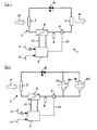
- the air conditioner 1 shows a first embodiment of an air conditioner according to the invention.
- the air conditioner 1 has a heat pump circuit 2.
- a first heat exchanger 3, a second heat exchanger 4, a third heat exchanger 8, a compressor 5, a collector 9 and an expansion valve 10 are provided.
- CO 2 is used as the refrigerant.
- Heat is extracted from the environment via the heat exchanger 3 and introduced into the heat pump cycle 2.
- the compressor 5 compresses the coolant and supplies it to the second heat exchanger 4.
- An air flow 16 through the heat exchanger 4 absorbs heat from the heat pump cycle 2 and is preferably directed into the interior of a vehicle to heat it. Via an expansion valve 10, the refrigerant is then passed back to the first heat exchanger 3, so that the heat pump cycle is closed.
- An advantage of a heat pump cycle is that more heat energy of Environment can be withdrawn and brought into the vehicle interior, as electrical or mechanical energy used to drive the compressor 5 must become.
- Fuel cell assembly 6 is provided. This is with an air supply 11 and a fuel supply line 12.
- the internal structure of the fuel cell assembly is of minor importance to the present invention.
- SOFC solid oxide fuel cell
- a reformer made of gasoline or diesel in a catalythic Reaction generates a hydrogen-containing gas, in turn, as a fuel gas for the SOFC serves.
- the heat generated in the fuel cell assembly 6 is via a cooling circuit Discharged 13 and supplied to the third heat exchanger 8. Furthermore the fuel cell assembly 6 provides electrical power via a conduit 14 is supplied to the electrically operated compressor 5 to this with to supply the required electrical power.
- the advantage of the air conditioner according to the invention with a heat pump cycle 2 occurs mainly when the air conditioner 1 used in stationary mode becomes.
- the air conditioner 1 used in stationary mode becomes.
- the first heat exchanger 3 for receiving ambient heat makes an important contribution to making the air conditioner 1 in stand mode an efficient To allow operation.
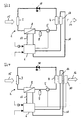
- the air conditioner according to the figure 2 is designed such that a front area and a rear area of the vehicle interior can be heated separately.
- two heat exchangers 4a and 4b instead of of the second heat exchanger 4 in Figure 1 are in Figure 2, two heat exchangers 4a and 4b, wherein an air flow 16a through the heat exchanger 4a the front area and an air flow 16b through the heat exchanger 4b the rear area can heat the vehicle.
- the waste heat of the fuel cell assembly 6 in addition to Heating purposes used by a cooling circuit 18 is provided, the fuel cell assembly 6 cools and the heat on an additional heat exchanger 17 leads, which also in the air flow 16 through the second heat exchanger 4 lies.
- the preheated by the second heat exchanger 4 air is thus further heated by the additional heat exchanger 17.
- the circulation 18 can of course with the circuit 13, the fuel cell assembly 6 with the third heat exchanger 8 connects, be coupled, for example by the third heat exchanger 8 and the additional heat exchanger 17 in series are switched. But it is cheaper, the heat exchanger 8 and 17 parallel to switch and provide an adjustment to the waste heat of the fuel cell assembly 6 in each operating situation as low as possible on the two Heat exchanger 8 and 17 to distribute.
- the thermal and electrical generated by the fuel cell assembly 6 Performance is thus used four times.
- the thermal power is applied to the heat exchanger 8 and 17 while the electric power to the compressor 5 and the PTC 18 is supplied.
- these power consumers so operated that the power generated by the fuel cell assembly 6 completely and optimally used for heating a vehicle interior becomes.
- a required for controlling the air conditioner controller is in the Figures not shown, but of course available.
- a motor-generator unit 7 used in the air conditioner of Figure 5, instead of the fuel cell assembly, a motor-generator unit 7 used.
- This includes an internal combustion engine 20 and a generator 21.
- the engine 20 is dimensioned to for the operation of the air conditioner and possibly for the supply of other electrical Consumers can be used. He is thus tuned to the stand operation a vehicle air conditioner.
- the compressor 5 and the generator 21 driven.
- the waste heat generated by the engine 20 becomes like in the fuel cell assembly on the one hand to the third heat exchanger. 8 and on the other hand led to the additional heat exchanger 17.
- the one of the Generator 21 generated electric power is in turn supplied to the PTC 19.
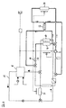
- FIG. 6 shows an air conditioning unit according to the invention, which is used both for heating and is also set up for cooling.
- Several components of the air conditioner will be used in both modes.
- the operating mode for Heating active The line sections used in this mode are for improvement the clarity drawn in bold, while the unused line sections thinly drawn.
- the operating mode shown corresponds to Arrangement of the air conditioner substantially the arrangement of Figure 3.
- Der Heat pump cycle 2 comprises the same components as the arrangement of Figure 3, only a plurality of valves are provided, which are for switching between the two modes are required.
- the cooling circuit of the fuel cell assembly 6 is shown in dashed lines. The waste heat of the fuel cell assembly 6, as in Figure 3, via the third heat exchanger 8 and the additional heat exchanger 17 out.
- the cooling circuit be closed via another heat exchanger 22. This is provided heat from the cooling circuit of the fuel cell assembly. 6 if not all the available heat for heating purposes should be used or when the air conditioner is in cooling mode. In this case, the heat is released to the environment.
- the electrical network of the air conditioner is shown. That of the fuel cell assembly 6 generated electric power is, as in the previous Embodiments used to drive the compressor 5. moreover Several blowers are driven, each with a flow of air through the Create heat exchanger. In addition, the electric power will be more Provided to consumers of the vehicle. By means of a DC / AC converter 30 can even generate an AC voltage of 110 V or 230 V. which is provided at a socket 31 and to the usual household Consumers can be connected.
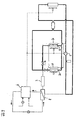
- FIG. 7 shows the air conditioner of FIG. 6 in cooling mode. Also on this mode the line sections used are shown in bold while the unused line sections are drawn thin.
- the heat exchanger 4 works as an evaporator and absorbs heat from the vehicle interior. These Heat is conducted to an internal heat exchanger 23 and the refrigerant circuit closed again to the evaporator 4.
- the expansion valve 10 is in this Operating mode operated in the opposite direction compared to the operating mode of Figure 6.
- the heat exchanger 23 is accommodated in a second cooling circuit, the one capacitor 24 and the compressor used in heating mode 5 includes. From a cost point of view is crucial that the compressor 5 can be used in both heating and cooling, since it is an expensive component that represents a significant proportion of the total cost of the air conditioner.
- the fuel cell assembly 6 is also required in cooling operation to electrical To generate energy. This also serves in dargestellen embodiment to drive the compressor 5. To the waste heat of the fuel cell assembly 6 dissipate, the cooling circuit 13 is in operation and gives heat through the heat exchanger 22 to the environment. The leading over the heat exchanger 17 Branch of the cooling circuit 13 is not active.
- the heat exchanger 23 is required when the refrigeration circuit is to be operated with CO 2 as the refrigerant.
- the heat exchanger 23 is required to achieve a high coefficient of performance (COP).
- CO 2 refrigerant exiting the condenser 24 is cooled on the way to the expansion valve 10 by means of the heat exchanger 23.
- the heat is absorbed by the exiting from the evaporator 4 refrigerant having a few degrees lower temperature than the exiting the condenser 24 refrigerant.
- FIG. 8 shows an air conditioner according to the invention which, like the air conditioner of FIG Figure 2 with heat exchangers 27 and 28 for the front and 25 and 26 for the rear area is equipped.
- Heat exchanger provided.
- the heat exchanger 28 and 26 are in heating mode used, while the heat exchanger 27 and 25 in the cooling mode use Find.
- the advantage of such a division is that when changing from heating to cooling mode a relatively high amount of moisture in the heat exchanger stored immediately after the change of the operating mode Slices fogged in a vehicle. This is through the separation of Heat exchanger avoided.
- FIG. 9 shows the air conditioner of FIG. 8 in cooling mode. It can be seen from this that in the cooling operation, the heat exchanger 27 and 25 are actively in operation.
Landscapes
- Physics & Mathematics (AREA)
- Thermal Sciences (AREA)
- Engineering & Computer Science (AREA)
- Mechanical Engineering (AREA)
- Air-Conditioning For Vehicles (AREA)
- Fuel Cell (AREA)
Applications Claiming Priority (2)
| Application Number | Priority Date | Filing Date | Title |
|---|---|---|---|
| DE102004002445A DE102004002445A1 (de) | 2004-01-16 | 2004-01-16 | Klimagerät zur Standklimatisierung eines Fahrzeugs |
| DE102004002445 | 2004-01-16 |
Publications (2)
| Publication Number | Publication Date |
|---|---|
| EP1557306A2 true EP1557306A2 (fr) | 2005-07-27 |
| EP1557306A3 EP1557306A3 (fr) | 2005-11-16 |
Family
ID=34625715
Family Applications (1)
| Application Number | Title | Priority Date | Filing Date |
|---|---|---|---|
| EP05000482A Withdrawn EP1557306A3 (fr) | 2004-01-16 | 2005-01-12 | Appareil de conditionnement d'air à l'arrêt d'un véhicule |
Country Status (4)
| Country | Link |
|---|---|
| US (1) | US20050218135A1 (fr) |
| EP (1) | EP1557306A3 (fr) |
| JP (1) | JP2005200011A (fr) |
| DE (1) | DE102004002445A1 (fr) |
Cited By (1)
| Publication number | Priority date | Publication date | Assignee | Title |
|---|---|---|---|---|
| EP2090448A1 (fr) * | 2008-02-18 | 2009-08-19 | Calsonic Kansei Corporation | Système de climatisation pour véhicule |
Families Citing this family (16)
| Publication number | Priority date | Publication date | Assignee | Title |
|---|---|---|---|---|
| DE102005060516A1 (de) * | 2005-12-12 | 2007-06-14 | Deutsches Zentrum für Luft- und Raumfahrt e.V. | Fahrzeug und Verfahren zum Betrieb eines Fahrzeugs |
| WO2009046269A2 (fr) * | 2007-10-03 | 2009-04-09 | Parker Hannifin Corp. | Système de gestion thermique de batterie/pile à combustible |
| DE102007051361B3 (de) * | 2007-10-26 | 2009-04-16 | Enerday Gmbh | Modulgehäuse für Brennstoffzellenmodule und Verfahren zum Bereitstellen eines Brennstoffzellenmoduls |
| DE102007051362A1 (de) | 2007-10-26 | 2009-04-30 | Enerday Gmbh | Kraftfahrzeug mit Schnittstelle zum Versorgen eines fahrzeugunabhängigen Stromverbrauchers |
| DE102007051566A1 (de) * | 2007-10-29 | 2009-04-30 | Enerday Gmbh | Klimatisierungssystem für ein Fahrzeug |
| JP2009190579A (ja) * | 2008-02-14 | 2009-08-27 | Calsonic Kansei Corp | 空気調和システム |
| DE102010024854B4 (de) | 2009-06-26 | 2022-05-12 | Denso Corporation | Klimaanlage für ein Fahrzeug |
| JP5614611B2 (ja) * | 2009-11-09 | 2014-10-29 | 剛正 山田 | 2次電池と固体酸化物型燃料電池とを備えた電動式移動体 |
| US8602141B2 (en) | 2010-04-05 | 2013-12-10 | Daimler Trucks North America Llc | Vehicle power system with fuel cell auxiliary power unit (APU) |
| JP5755490B2 (ja) * | 2011-04-18 | 2015-07-29 | トヨタ自動車株式会社 | 冷却装置 |
| JP6304578B2 (ja) * | 2013-03-06 | 2018-04-04 | パナソニックIpマネジメント株式会社 | 車両用空調装置 |
| DE102013012926A1 (de) * | 2013-08-02 | 2015-02-05 | Man Truck & Bus Ag | Wärmepumpe, insbesondere zur Heizung eines Fahrzeuginnenraums, sowie Verfahren zum Betreiben einer Wärmepumpe |
| KR101775441B1 (ko) * | 2015-09-09 | 2017-09-07 | 제주대학교 산학협력단 | 연료전지 자동차의 공기조화장치 |
| DE102015218825B4 (de) * | 2015-09-30 | 2026-03-12 | Bayerische Motoren Werke Aktiengesellschaft | Verfahren und Steuerungssystem zur Klimatisierung eines Fahrzeugs |
| JP6565744B2 (ja) * | 2016-03-10 | 2019-08-28 | 株式会社デンソー | 空調装置 |
| CN115891625B (zh) * | 2021-09-30 | 2024-10-11 | 比亚迪股份有限公司 | 车辆的热管理系统以及车辆 |
Family Cites Families (16)
| Publication number | Priority date | Publication date | Assignee | Title |
|---|---|---|---|---|
| JPS61155013A (ja) * | 1984-12-27 | 1986-07-14 | Daihatsu Motor Co Ltd | サブエンジン搭載車 |
| US4825663A (en) * | 1987-11-16 | 1989-05-02 | Paccar Inc. | Auxiliary air conditioning system for trucks and other heavy duty vehicles |
| JP3329091B2 (ja) * | 1994-09-28 | 2002-09-30 | 株式会社デンソー | ヒートポンプ式車両用空調装置 |
| DE19738250C2 (de) * | 1997-09-02 | 2000-11-16 | Daimler Chrysler Ag | Kraftfahrzeugklimaanlage mit Kompressoreinheit |
| US6053266A (en) * | 1997-12-01 | 2000-04-25 | Dbb Fuel Cell Engines Gmbh | Fuel cell engine having a propulsion motor operatively connected to drive a fluid supply device |
| DE19813674C1 (de) * | 1998-03-27 | 1999-04-15 | Daimler Chrysler Ag | Vorrichtung und Verfahren zum Heizen und Kühlen eines Nutzraumes eines Kraftfahrzeuges |
| DE19850829C1 (de) * | 1998-11-04 | 2000-03-16 | Valeo Klimasysteme Gmbh | Kühl-Heiz-Kreis für ein Fahrzeug |
| DE19953940A1 (de) * | 1998-11-17 | 2000-05-25 | Bosch Gmbh Robert | Antriebsaggregat für ein Kraftfahrzeug |
| FR2787392B1 (fr) * | 1998-12-21 | 2002-01-11 | Valeo Climatisation | Dispositif de chauffage-climatisaiton d'encombrement reduit pour vehicule automobile |
| DE10006513B4 (de) * | 2000-02-15 | 2014-12-24 | Behr Gmbh & Co. Kg | Klimaanlage für ein Kraftfahrzeug mit Wärmepumpen- und/oder Reheat-Betriebsart |
| JP4517529B2 (ja) * | 2000-07-21 | 2010-08-04 | 株式会社日本自動車部品総合研究所 | ヒートポンプサイクル、加熱装置、車両用暖房装置、暖房装置および蒸気圧縮式冷凍サイクル |
| DE10128877A1 (de) * | 2001-06-15 | 2002-12-19 | Behr Gmbh & Co | Fahrzeug-Kühlkreislauf für die Kühlung einer temperaturerhöhenden Einrichtung mittels eines Kühlmittels |
| US6796367B2 (en) * | 2001-08-13 | 2004-09-28 | Inventive Technologies Foundation | Vehicle battery charging and air conditioning operating unit |
| US20030070849A1 (en) * | 2001-10-17 | 2003-04-17 | Whittaker Clark Thomas | Auxiliary power unit for vehicles |
| US6865901B2 (en) * | 2002-05-29 | 2005-03-15 | Webasto Thermosysteme International Gmbh | System with an internal combustion engine, a fuel cell and a climate control unit for heating and/or cooling the interior of a motor vehicle and process for the operation thereof |
| DE10223949B4 (de) * | 2002-05-29 | 2007-11-08 | Webasto Ag | System und Verfahren zum Kühlen beziehungsweise Heizen eines Fahrzeuginnenraums |
-
2004
- 2004-01-16 DE DE102004002445A patent/DE102004002445A1/de not_active Ceased
-
2005
- 2005-01-12 EP EP05000482A patent/EP1557306A3/fr not_active Withdrawn
- 2005-01-14 JP JP2005008083A patent/JP2005200011A/ja active Pending
- 2005-01-18 US US11/036,174 patent/US20050218135A1/en not_active Abandoned
Cited By (1)
| Publication number | Priority date | Publication date | Assignee | Title |
|---|---|---|---|---|
| EP2090448A1 (fr) * | 2008-02-18 | 2009-08-19 | Calsonic Kansei Corporation | Système de climatisation pour véhicule |
Also Published As
| Publication number | Publication date |
|---|---|
| DE102004002445A1 (de) | 2005-08-11 |
| JP2005200011A (ja) | 2005-07-28 |
| US20050218135A1 (en) | 2005-10-06 |
| EP1557306A3 (fr) | 2005-11-16 |
Similar Documents
| Publication | Publication Date | Title |
|---|---|---|
| EP1557306A2 (fr) | Appareil de conditionnement d'air à l'arrêt d'un véhicule | |
| DE102011107540B4 (de) | Verfahren zum Betreiben eines Kraftwagens in einem Sportbetriebsmodus | |
| DE19850829C1 (de) | Kühl-Heiz-Kreis für ein Fahrzeug | |
| DE102016006682B4 (de) | Verfahren zum Betreiben einer Klimaanlage eines Elektro- oder Hybridfahrzeugs sowie Klimaanlage zur Durchführung des Verfahrens | |
| DE19925443B4 (de) | Klimatisierung mit elektrischem Kompressor | |
| DE60307932T2 (de) | Vorrichtung und Verfahren zum Kontrollieren eines elektromotorisch angetriebenen Gebläses eines Kraftfahrzeuges | |
| DE10223949A1 (de) | System und Verfahren zum Kühlen beziehungsweise Heizen eines Fahrzeuginnenraums | |
| DE10161254A1 (de) | Klimatisierungseinrichtung für ein Fahrzeug | |
| DE112014004894T5 (de) | Vorrichtung und Verfahren zum Betrieb eines Schaltelements und Fahrzeug-Klimatisierungsvorrichtung | |
| EP1706282A1 (fr) | Climatiseur pour un vehicule automobile | |
| DE102011075284A1 (de) | Verfahren zum Konditionieren eines Wärme-/Kältespeichers sowie Fahrzeug mit einem Wärme-/Kältespeicher | |
| DE102011051624A1 (de) | Kühlsystem zum Einsatz in einem Kraftfahrzeug | |
| DE102021107772A1 (de) | Steuerung für das thermische system eines fahrzeugs | |
| DE10346974A1 (de) | Klimaanlage für ein Hybridfahrzeug | |
| DE102012215971A1 (de) | Verfahren zum thermischen Konditionieren eines Verbrennungsmotors und/oder eines Fahrgastraums eines Fahrzeugs sowie Fahrzeug | |
| DE102022131349A1 (de) | Integriertes wärmemanagementsystem für ein brennstoffzellenfahrzeug | |
| DE102018211559B4 (de) | Fahrzeug mit einer Klimatisierungsvorrichtung zum Erwärmen und Kühlen eines elektrischen Energiespeichers | |
| EP3294578A1 (fr) | Système de climatisation de véhicule et procédé de fonctionnement | |
| EP4351901B1 (fr) | Ensemble pompe à chaleur pour véhicule hybride ou électrique | |
| DE102019132816A1 (de) | Wärmemanagementsystem für ein Kraftfahrzeug und Kraftfahrzeug mit einem solchen | |
| DE102021107773A1 (de) | Steuerung für das thermische System eines Fahrzeugs | |
| DE10258196A1 (de) | System mit einem Verbrennungsmotor und einer Brennstoffzelle | |
| DE10259071B4 (de) | Temperiersystem für ein Fahrzeug | |
| DE102013009561A1 (de) | Verfahren zur Steuerung der Kühlung einer Traktionsbatterie | |
| EP0569991A1 (fr) | Dispositif de chauffage intérieur pour automobiles |
Legal Events
| Date | Code | Title | Description |
|---|---|---|---|
| PUAI | Public reference made under article 153(3) epc to a published international application that has entered the european phase |
Free format text: ORIGINAL CODE: 0009012 |
|
| AK | Designated contracting states |
Kind code of ref document: A2 Designated state(s): AT BE BG CH CY CZ DE DK EE ES FI FR GB GR HU IE IS IT LI LT LU MC NL PL PT RO SE SI SK TR |
|
| AX | Request for extension of the european patent |
Extension state: AL BA HR LV MK YU |
|
| PUAL | Search report despatched |
Free format text: ORIGINAL CODE: 0009013 |
|
| AK | Designated contracting states |
Kind code of ref document: A3 Designated state(s): AT BE BG CH CY CZ DE DK EE ES FI FR GB GR HU IE IS IT LI LT LU MC NL PL PT RO SE SI SK TR |
|
| AX | Request for extension of the european patent |
Extension state: AL BA HR LV MK YU |
|
| RIC1 | Information provided on ipc code assigned before grant |
Ipc: 7B 60H 1/22 B Ipc: 7B 60H 1/32 B Ipc: 7B 60H 1/00 A |
|
| AKX | Designation fees paid |
Designated state(s): AT BE BG CH CY CZ LI |
|
| 17P | Request for examination filed |
Effective date: 20060405 |
|
| RBV | Designated contracting states (corrected) |
Designated state(s): AT BE BG CH CY CZ DE DK EE ES FI FR GB GR HU IE IS IT LI LT LU MC NL PL PT RO SE SI SK TR |
|
| REG | Reference to a national code |
Ref country code: DE Ref legal event code: 8566 |
|
| 17Q | First examination report despatched |
Effective date: 20070201 |
|
| GRAP | Despatch of communication of intention to grant a patent |
Free format text: ORIGINAL CODE: EPIDOSNIGR1 |
|
| RIN1 | Information on inventor provided before grant (corrected) |
Inventor name: HORN, OLIVER Inventor name: KHELIFA, NOUREDDINE Inventor name: KRAEMER, WOLFGANG |
|
| STAA | Information on the status of an ep patent application or granted ep patent |
Free format text: STATUS: THE APPLICATION IS DEEMED TO BE WITHDRAWN |
|
| 18D | Application deemed to be withdrawn |
Effective date: 20081009 |