EP1557321B1 - Procédé pour avertir un conducteur d'un véhicule - Google Patents
Procédé pour avertir un conducteur d'un véhicule Download PDFInfo
- Publication number
- EP1557321B1 EP1557321B1 EP05101988A EP05101988A EP1557321B1 EP 1557321 B1 EP1557321 B1 EP 1557321B1 EP 05101988 A EP05101988 A EP 05101988A EP 05101988 A EP05101988 A EP 05101988A EP 1557321 B1 EP1557321 B1 EP 1557321B1
- Authority
- EP
- European Patent Office
- Prior art keywords
- driver
- vehicle
- warning
- attentiveness
- determined
- Prior art date
- Legal status (The legal status is an assumption and is not a legal conclusion. Google has not performed a legal analysis and makes no representation as to the accuracy of the status listed.)
- Expired - Lifetime
Links
Images


Classifications
-
- B—PERFORMING OPERATIONS; TRANSPORTING
- B60—VEHICLES IN GENERAL
- B60R—VEHICLES, VEHICLE FITTINGS, OR VEHICLE PARTS, NOT OTHERWISE PROVIDED FOR
- B60R16/00—Electric or fluid circuits specially adapted for vehicles and not otherwise provided for; Arrangement of elements of electric or fluid circuits specially adapted for vehicles and not otherwise provided for
- B60R16/02—Electric or fluid circuits specially adapted for vehicles and not otherwise provided for; Arrangement of elements of electric or fluid circuits specially adapted for vehicles and not otherwise provided for electric constitutive elements
- B60R16/023—Electric or fluid circuits specially adapted for vehicles and not otherwise provided for; Arrangement of elements of electric or fluid circuits specially adapted for vehicles and not otherwise provided for electric constitutive elements for transmission of signals between vehicle parts or subsystems
- B60R16/0231—Circuits relating to the driving or the functioning of the vehicle
- B60R16/0232—Circuits relating to the driving or the functioning of the vehicle for measuring vehicle parameters and indicating critical, abnormal or dangerous conditions
Definitions
- the invention is based on a method for warning a vehicle driver according to the preamble of the main claim. It is known to warn a driver by warning displays, which are preferably arranged in an instrument cluster in front of the driver, against malfunction of a vehicle or other dangerous critical situations. For this purpose, it is known to evaluate vehicle functions for the warning displays by means of sensors, for example the thickness of the brake linings, the cooling water temperature, the oil pressure or the outside temperature. Furthermore, sensors are known which detect obstacles in the track in front of or behind the vehicle, such as a parking aid or an ACC system (Adaptive Cruise Control), which detect distances to obstacles by means of electromagnetic or acoustic sensors.
- ACC system Adaptive Cruise Control
- a piece of paper or a piece of wood on the road and the driver differs briefly over a boundary of the lane marking, he is warned on the one hand before the obstacle and on the other hand when crossing the lane boundary marker, although he has seen the obstacle on the one hand and the lane marking has overrun deliberately and on the other hand also by crossing the paper or piece of wood no damage to the vehicle would have arisen.
- a driver may be overwhelmed with unnecessary warnings that lower his or her threshold to warnings from the vehicle electronics as a whole. A possibly important warning may then no longer be perceived by a driver, so that he no longer reacts to a warning despite a suitable warning system in a real danger situation
- a logic circuit activates a signal of a delay unit when an exhausting driving situation exists and / or a control is currently being operated by the driver. This temporarily relieves a driver from presenting new information during the driving situation when his concentration is required for other temporary tasks.
- a display system for a vehicle is known in which a driver's line of sight is detected and a warning is displayed on the display of the vehicle that the driver is currently looking at.
- the inventive method with the features of the main claim has the advantage that prior to the issue of a warning attention of the driver is determined and that issued a warning of a critical situation only at a low attention of the driver becomes. This will alert a driver only to hazards that are likely to escape his attention, reducing the number of superfluous warnings. Incoming warnings are therefore observed by the driver, so that an efficient issuance of warnings with a high level of driver acceptance is achieved. By issuing warnings only with low driver attention, a driver will pay particular attention to the warnings issued.
- the measures listed in the dependent claims advantageous refinements and improvements of the main claim method are possible. It is particularly advantageous to detect a driver's image by means of a camera device and to draw attention to the driver's attention by means of processing by an arithmetic unit, since in contrast to indirect methods, the attention and, in particular, the waking state of the driver are determined directly. It is particularly advantageous to determine the line of sight, the blinking frequency and / or the head position of the driver. A high eyelid frequency or closed eyelids, as well as a lowered head, indicate fatigue for the driver. It is advantageous to evaluate the viewing direction so that only the direction in which the driver looks, a high attention is assigned, while the other directions in which he does not look and therefore lie outside his field of view, a low attention is assigned.
- a driver looks ahead and is e.g. detected by a distance measuring device too low, rearward distance of the vehicle to an obstacle, so takes place in addition to an optical warning, for. by means of a light-emitting diode display very early an additional audible warning, e.g. already at a distance of 2 m.
- an additional audible warning e.g. already at a distance of 2 m.
- an additional audible warning In a driver whose view is directed in the vehicle to the rear, takes place only at a rear distance of preferably 50 cm, an additional audible warning.
- a driver's attention dependent on the operation of the vehicle arranged devices If e.g. If a driver determines that a navigation device is being programmed or is operating a car radio unit, he will be given less attention for that period. The same applies in the event that the arranged in the vehicle phone is used.
- a driver's state of tiredness via sensors, by determining preferably the body temperature and / or pulse frequency. Also via this determined, physiological data is a direct information about the driver's attention possible.
- a warning is emitted acoustically in an advantageous manner since the driver's line of sight does not have to be directed to a warning display.
- FIG. 1 shows the arrangement of sensors for carrying out the method according to the invention in a vehicle
- Figure 2 shows a circuit according to the invention sensors to a computing unit with an output unit for carrying out the method according to the invention
- Figure 3 shows an embodiment of a sequence of the method according to the invention
- Figure 4 shows an embodiment for an evaluation step of the method according to the invention.
- the method of the invention can be used in a variety of vehicles, e.g. in rail vehicles, in airplanes, in ships and in motor vehicles. Furthermore, a use in a remote control of vehicles or other machines from a command post is possible.
- the method according to the invention will be explained below with reference to the embodiment in a motor vehicle.
- a combination of sensors, which serve to detect critical situations for the vehicle, can be chosen arbitrarily. In the cited embodiment, an advantageous combination of sensors was selected, however, in which, depending on the design of the vehicle, additional sensors can be added or sensors can also be omitted for reasons of cost.
- a passenger vehicle 1 with a windshield 2, a vehicle roof 3 and a rear window 4 in a plan view of the vehicle.
- a camera device 5 is arranged, which covers below the vehicle roof 3 through the vehicle roof 3 and therefore dashed lines in the figure 1 is located.
- a radar device 8 and a camera device 9 is arranged at a front side 6 of the vehicle behind a radiator cover 7, a radar device 8 and a camera device 9 is arranged.
- a left side mirror 12 is arranged with a first exterior mirror camera 13.
- a right side mirror 14 with a second exterior mirror camera 15 is arranged.
- a distance sensor 16 and on the right side surface 11, a distance sensor 17 is arranged.
- a steering wheel 20 is arranged with physiological sensors 21 in front of a driver, which are located in a handle portion of the steering wheel 20. Between a driver and a passenger electric devices 22 are arranged in a central region of the vehicle. Dashed lines in the area of the dashboard show a computing unit 23 which serves to evaluate the sensors arranged in the passenger vehicle 1. A connection from the arithmetic unit 23 to the individual sensors is not shown in FIG. An output of warnings via speakers 24, preferably via speakers of a car radio, and / or via a display 25, which is preferably arranged in an instrument cluster in front of the driver.
- the physiological sensors 21 are touched during the control of the passenger vehicle 1 when a touch of the steering wheel 20 by a driver, wherein a pulse rate preferably via a capacitive measurement and the body temperature is preferably determined by an infrared measurement. These data are then forwarded to the arithmetic unit 23, in which a memory unit with limit values is arranged. The arithmetic unit 23 compares the physiological sensor data with the stored limits and determines whether the driver is awake or drowsy depending on the comparison. If the driver is sleepy, he will be given less attention. Otherwise, based on this criterion, low driver attention is not detected. Furthermore, an image of the driver is taken by the camera device 5 and forwarded to the arithmetic unit 23.
- the driver's attention is determined to be low. Furthermore, a viewing direction of the driver is determined from the head position of the driver. For all directions other than the driver's line of sight, which at least almost completely includes the field of vision perceivable by the driver, the driver's attention is thereby set as a low attention. Attention may be paid to the direction of the driver's attention unless, for example, a driver's previously determined fatigue is in conflict.
- the driver's attention is digitally determined between "high attention” and "lower attention.” Furthermore, it is also possible to further divide the size of the attention or to set it on a continuous scale.
- the attention of the driver is first determined individually for the driver as a whole and also for different possible directions of the driver. If, for example, it is determined via the physiological sensors 21 or by means of image evaluation by the camera device that the driver is asleep, the attention for any of the viewing directions can not be high. On the other hand, if it is determined that the driver is not asleep, so can the attention for a maximum of one line of sight of the driver to be high.
- Viewing directions may, in a preferred embodiment, be the "forward" viewing directions toward the front 6, "left” toward the left side surface 10, "right” toward the right side surface 11, and “backward” toward the rear surface 18 be set of the vehicle.
- an operation of the electrical devices 22 is detected.
- the electrical devices 22 are implemented as a car radio device, a navigation device, and a mobile telephone unit. Once the mobile phone unit is operated, the driver's attention is set to a low value. If more than two actuations of operating elements are detected on the car radio device and on the navigation device in a preferred embodiment over a period of 20 seconds, ie an operating frequency greater than 0.1 Hz, a low driver's attention is also determined.
- FIG. 24 Further sensors that monitor vehicle functions such as the oil pressure, the cooling water temperature or the brake circuit are not shown in FIG. As a rule, such vehicle malfunctions occur very rarely and are important for the driver, even in the case of an attentive driver since, in general, an indication is only given via small warning lamps in the display 25. An additional audible warning is therefore output via the speakers 24 regardless of the driver's attention.
- the speakers 24 are executed in a preferred embodiment as speakers of the car radio device, which is a part of the electrical equipment 22.
- the route of the vehicle is observed.
- An image of the travel path is transmitted to the computing unit 23, which determines whether the passenger vehicle 1 is still on the route in which a position of lane boundaries and the position of the passenger vehicle 1 to the lane boundaries is determined. If it is determined that the driver is attentive, an acoustic warning is issued to the driver only if the lane boundaries are exceeded for a long time. If, on the other hand, it is determined by the arithmetic unit 23 that the driver only briefly exceeds the lane boundaries, a warning is suppressed.
- the camera device 9 is arranged next to the radar device 8 behind the radiator cover 7, so that neither the camera device 9 nor the radar device 8 are visible to a viewer outside the vehicle.
- the radar device 8 monitors the distance to a preceding vehicle or to an obstacle located in front of the vehicle.
- a warning up to a distance of 75% of the so-called "half speed distance", in which from the speed in kilometers by dividing by 2 a preferably observed distance is determined. At 100 km / h these are eg 50 m. If it is determined by the arithmetic unit 23 that the driver is alert, a warning is issued only when the distance falls below a distance of 38 m, unless the distance is automatically controlled by the arithmetic unit 23 by acting on the drive train or on the brakes. If, on the other hand, less attention is given to the driver, the driver is warned if the distance is less than 50 m.
- a reduced attention is detected when the driver is not looking in the direction of the front side 6 of the vehicle.
- the first outside mirror camera and the second Exterior mirror camera 15 are used to monitor a so-called blind spot of the vehicle, so an area that is not visible in the exterior mirrors 12 and 14 of the vehicle for a driver. If, for example, determined by an operation of a turn signal lever, not shown in Figure 1, that a driver wants to change the road, and is determined by the exterior mirror cameras 13, 15, a vehicle in the respective blind spot, so with a low attention of the driver, a warning in particular when the driver is not looking in the direction of the left side surface 10 or the right side surface 11 of the vehicle.
- the distance sensors 16, 17, 19 measure a distance to possible obstacles.
- the distance sensors 16, 17, 19 are preferably designed as ultrasonic sensors, but may also be used as electromagnetic sensors, e.g. Microwave sensors, be executed. If a high level of driver attention is detected in the direction of the rear side 18 by evaluating its viewing direction, a warning is preferably only issued when the distance from the distance sensors 16, 17, 19 to an obstacle is 50 cm or less. If, on the other hand, a low level of attention is detected or it is determined that the driver is looking forward, a warning to the driver in a preferred exemplary embodiment is already detected if the distance from, for example, 2 m to one of the distance sensors 16, 17, 19 is undershot Obstacle issued.
- Critical situations for the vehicle may be, for example, acute vehicle defects, such as a defect in the brake system, a small distance of the vehicle to an obstacle, exceeding a lane boundary marking or too short distance to a vehicle in front or to the side. A determination is made in each case by suitable sensors.
- FIG. 2 shows a circuit of vehicle sensors to the computing unit 23.
- a memory unit 31 for storing limit values with which the values determined by the vehicle sensors are compared.
- the arithmetic unit 23 decides whether the driver is attentive or not. If the arithmetic unit 23 determines that a warning is issued, then the command for issuing a warning is forwarded to an output unit 32. By means of the output unit 32, a warning is forwarded to a display unit 33 in which the warning is displayed.
- the display unit 33 is preferably implemented in a location well visible to the driver, e.g. in the form of the display 25 according to FIG. 1.
- a voice-forming unit 34 converts the warning into a voice output which, like a warning sound, is output via a loudspeaker 24.
- the camera device 5, the radar device 8, the camera device 9, a first exterior mirror camera 13, a second exterior mirror camera 15, the distance sensors 16, 17, 19, the physiological sensors 21, the electrical devices 22 and in FIG. 1 are not shown vehicle sensors, eg a coolant control 35 and a brake system control 36 connected.
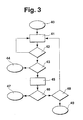
- FIG. 3 shows a first exemplary embodiment of a method sequence according to the invention.
- an initialization step 40 in which the method according to the invention is started for example at a Start of the passenger vehicle 1, is further branched to a determination step 41.
- the radar device 8, the camera device 9, the exterior mirror cameras 13, 15 and the distance sensors 16, 17, 19 are queried as to whether a critical situation exists. This is checked in a subsequent first test step 42. If there is no critical situation, then branching back to the determination step 41. On the other hand, if it is determined that a critical situation exists, a further branch is made to a second checking step 43. In the second checking step 43, it is checked whether the critical situation determined by the determining step 41 has a high priority.
- third test step 46 it is checked whether the determined attention is low or high. If the determined attention is low, it branches to an output step 47 in which a warning is issued in the same way as in the output step 44. On the other hand, in the third test step 46 If the driver's attention for the corresponding area has been determined to be high, a further branch is made to a fourth test step 48. In the fourth test step 48, it is checked whether the fourth test step 48 has already been achieved repeatedly for the same, determined, critical situation. This is the case, for example, when a driver exceeds the road boundary with the vehicle in the longer term. In this case, it branches to an output step 49 in which a warning as well as the output step 44 is output.
- the fourth checking step 48 if the fourth checking step 48 reveals that a critical situation ascertained in the determining step 41 is reached for the first time, then branching is made to the determining step 41 and subsequently it is checked whether the critical situation still exists.
- a counter not shown in FIG. 3, is incremented, which is reset after a predetermined time, if the critical situation has not recurred or not consists.
- the attention determination step 45 from FIG. 3 is shown in detail.
- a first test step 51 it is checked in a first test step 51 whether the physiological sensors 21 give an indication that the driver is tired. If fatigue is detected, for example, from a low body temperature or a low pulse beat, the procedure branches to a first setting step 52, which sets the driver's attention low.
- the memory unit 31 can store non-volatile specific physiological characteristics of the driver.
- the physiological data is in a denomination range If there is no conclusion as to driver fatigue, then a further branch is made to a second test step 53. In the second test step 53 it is determined based on an evaluation of the determined by the camera device 5 image of the driver, whether the driver is tired.
- a branch is made to a second setting step 54, in which it is likewise established that the driver's attention is low. Otherwise, a further branch is made to a third checking step 55, in which it is checked whether the mobile telephone is activated. If so, low driver attention is also set in a third commit step 56. If, on the other hand, it is determined that the mobile telephone is not being used, a further branch is made to a fourth checking step 57, in which it is checked whether an increased frequency of operation of the remaining electrical devices 22, for example the navigation device or the car radio device, has taken place within a predetermined time interval.
- a further branching step 58 in which a low attention of the driver is determined. If no increased operating frequency is detected, a further branch is made to a fifth checking step 59, in which it is checked whether the driver's line of sight coincides with the direction which is important for the critical situation determined in the determining step 41. If, for example, the critical situation is a reduced distance of the vehicle from an obstacle located behind it, in the event that the driver also looks backwards, the driver will receive a high level of attention in a fifth setting step 60 following the fifth checking step 59 determined. On the other hand, if it is determined that the viewing direction important for the critical situation does not coincide with the driver's line of vision, then the route branches to a sixth setting step 61 where a low driver's attention is detected.
- an output of the warning relevant to a direction in which the driver is not looking toward a warning of a direction in which the driver is watching, is issued first has directed. This ensures that alerts are issued first for critical situations that are not in the driver's field of vision.
Landscapes
- Engineering & Computer Science (AREA)
- Automation & Control Theory (AREA)
- Mechanical Engineering (AREA)
- Traffic Control Systems (AREA)
- Auxiliary Drives, Propulsion Controls, And Safety Devices (AREA)
Claims (7)
- Procédé pour avertir un conducteur d'un véhicule, selon lequel des capteurs du véhicule saisissant une situation critique on détermine une vigilance du conducteur, on émet un avertissement concernant la situation critique en fonction de la vigilance du conducteur, on saisit une commande et/ou une utilisation d'appareils disposés dans le véhicule par le conducteur et on détermine et une faible vigilance du conducteur, lorsqu'un des appareils est utilisé et/ou lorsqu'une valeur prédéterminée d'une fréquence de commande d'un des appareils est dépassée,
caractérisé en ce qu'
on émet un avertissement uniquement lorsque la vigilance du conducteur est faible. - Procédé selon la revendication 1,
caractérisé en ce qu'
on détecte une image du conducteur à l'aide d'un dispositif de caméra, on traite l'image avec une unité de calculateur et on détermine la vigilance du conducteur à partir de l'image. - Procédé selon la revendication 2,
caractérisé en ce qu'
on détermine la vigilance du conducteur à l'aide de la direction du regard, de la fréquence de battement des paupières et/ou de la position de la tête. - Procédé selon l'une quelconque des revendications 2 et 3,
caractérisé en ce qu'
on accorde une grande attention à la direction du regard du conducteur et on accorde peu d'attention à d'autres directions. - Procédé selon l'une quelconque des revendications précédentes,
caractérisé en ce qu'
on émet l'avertissement au moins de façon acoustique. - Dispositif pour la mise en oeuvre du procédé selon l'une quelconque des revendications précédentes, avec des capteurs du véhicule et avec au moins un appareil disposé dans le véhicule, les capteurs du véhicule saisissant une situation critique, selon lequel on détermine une vigilance du conducteur, on émet un avertissement contre la situation critique en fonction de la vigilance du conducteur, on saisit une commande et/ou une utilisation d'au moins un appareil par le conducteur, et on détermine une faible vigilance du conducteur, lorsque l'un des appareils est utilisé et/ou lorsqu'une valeur prédéterminée d'une fréquence de commande d'un des appareils est dépassée,
caractérisé en ce que
le dispositif émet un avertissement uniquement lorsque la vigilance du conducteur est faible. - Dispositif selon la revendication 6,
caractérisé en ce que
les capteurs du véhicule sont un dispositif d'aide au parcage, un dispositif de maintien de distance, un dispositif de reconnaissance d'obstacles dans un angle mort et/ou un dispositif de surveillance des limites de la chaussée, et le dispositif disposé dans le véhicule est un autoradio, un dispositif de navigation ou un téléphone mobile.
Applications Claiming Priority (3)
| Application Number | Priority Date | Filing Date | Title |
|---|---|---|---|
| DE10039795 | 2000-08-16 | ||
| DE10039795A DE10039795C2 (de) | 2000-08-16 | 2000-08-16 | Verfahren zur Warnung eines Fahrers eines Fahrzeugs |
| EP01119211A EP1182089B2 (fr) | 2000-08-16 | 2001-08-09 | Procédé pour avertir un conducteur d'un véhicule |
Related Parent Applications (1)
| Application Number | Title | Priority Date | Filing Date |
|---|---|---|---|
| EP01119211A Division EP1182089B2 (fr) | 2000-08-16 | 2001-08-09 | Procédé pour avertir un conducteur d'un véhicule |
Publications (2)
| Publication Number | Publication Date |
|---|---|
| EP1557321A1 EP1557321A1 (fr) | 2005-07-27 |
| EP1557321B1 true EP1557321B1 (fr) | 2007-07-18 |
Family
ID=7652459
Family Applications (2)
| Application Number | Title | Priority Date | Filing Date |
|---|---|---|---|
| EP01119211A Expired - Lifetime EP1182089B2 (fr) | 2000-08-16 | 2001-08-09 | Procédé pour avertir un conducteur d'un véhicule |
| EP05101988A Expired - Lifetime EP1557321B1 (fr) | 2000-08-16 | 2001-08-09 | Procédé pour avertir un conducteur d'un véhicule |
Family Applications Before (1)
| Application Number | Title | Priority Date | Filing Date |
|---|---|---|---|
| EP01119211A Expired - Lifetime EP1182089B2 (fr) | 2000-08-16 | 2001-08-09 | Procédé pour avertir un conducteur d'un véhicule |
Country Status (2)
| Country | Link |
|---|---|
| EP (2) | EP1182089B2 (fr) |
| DE (3) | DE10039795C2 (fr) |
Families Citing this family (83)
| Publication number | Priority date | Publication date | Assignee | Title |
|---|---|---|---|---|
| DE10223210A1 (de) * | 2002-05-24 | 2003-12-04 | Stotz Feinmesstechnik Gmbh | Verfahren und Vorrichtung zum Alarmieren eines Fahrzeugführers |
| DE10238324B4 (de) * | 2002-08-21 | 2014-02-13 | Volkswagen Ag | Verfahren und Vorrichtung zur Überwachung des Fahrers eines Kraftfahrzeugs |
| DE10240018B4 (de) * | 2002-08-27 | 2016-09-15 | Volkswagen Ag | Verfahren und Vorrichtung zur Erzeugung eines Warnsignals vor einer Notmaßnahme eines Fahrerassistenzsystems eines Fahrzeugs |
| DE10241922A1 (de) | 2002-09-10 | 2004-03-18 | Bayerische Motoren Werke Ag | Fahrerassistenzsystem für ein Strassenfahrzeug |
| DE10244205A1 (de) † | 2002-09-23 | 2004-03-25 | Robert Bosch Gmbh | Verfahren und Einrichtung zur Verhinderung der Kollision von Fahrzeugen |
| AU2002341216A1 (en) * | 2002-11-13 | 2004-06-03 | Hannah Collip | A vehicle interior air treatment apparatus |
| DE10305935A1 (de) * | 2003-02-13 | 2004-08-26 | Valeo Schalter Und Sensoren Gmbh | Vorrichtung zur Erfassung von Objekten im Umfeld eines Kraftfahrzeugs |
| DE10322458A1 (de) | 2003-05-16 | 2004-12-02 | Daimlerchrysler Ag | Verfahren und Vorrichtung zur Beeinflussung der Beanspruchung eines Fahrers in einem Kraftfahrzeug |
| DE10339647A1 (de) | 2003-08-28 | 2005-03-24 | Robert Bosch Gmbh | Vorrichtung zur Fahrerwarnung |
| DE10340870A1 (de) | 2003-09-04 | 2005-04-28 | Siemens Ag | Verfahren zur Steuerung der Ausgabe von Meldungen |
| DE10343683A1 (de) * | 2003-09-20 | 2005-04-21 | Daimler Chrysler Ag | Informationssystem für Kraftfahrzeuge |
| DE102004011950B4 (de) | 2004-03-11 | 2025-02-06 | Bayerische Motoren Werke Aktiengesellschaft | Verfahren zur Ausgabe von Informationen in einem Fahrzeug |
| DE102004012475A1 (de) * | 2004-03-15 | 2005-10-06 | Carl Zeiss Jena Gmbh | Anzeigevorrichtung |
| DE102004022113A1 (de) * | 2004-05-05 | 2005-11-24 | Robert Bosch Gmbh | Überwachung eines PKW-Anhängers mit einer Rückfahrkamera |
| DE102004039305A1 (de) | 2004-08-12 | 2006-03-09 | Bayerische Motoren Werke Ag | Vorrichtung zur Auswertung der Aufmerksamkeit eines Fahrers bei einem Kollisionsvermeidungssystem in Kraftfahrzeugen |
| DE102004047136A1 (de) * | 2004-09-27 | 2006-04-13 | Daimlerchrysler Ag | Verfahren zum Erlernen der Reaktionen des Fahrers eines Fahrzeugs |
| DE102004048009A1 (de) * | 2004-10-01 | 2006-04-06 | Robert Bosch Gmbh | Verfahren und Vorrichtung zur Fahrerunterstützung |
| DE102004048011A1 (de) | 2004-10-01 | 2006-04-06 | Robert Bosch Gmbh | Verfahren und Vorrichtung zur Fahrerunterstützung |
| DE102004054472B3 (de) * | 2004-11-11 | 2006-03-16 | Bayerische Motoren Werke Ag | Fahrerassistenzsystem |
| DE102005010229A1 (de) * | 2005-03-05 | 2006-09-14 | Daimlerchrysler Ag | Verfahren zum Ausgeben von Hilfeinformationen |
| DE102005010230B4 (de) * | 2005-03-05 | 2008-06-19 | Daimler Ag | Verfahren zum Ausgeben von Hilfeinformationen |
| DE102005018688B4 (de) * | 2005-04-22 | 2025-07-10 | Bayerische Motoren Werke Aktiengesellschaft | Fahrerassistenzsystem |
| DE102005021141A1 (de) * | 2005-05-06 | 2006-11-09 | Bayerische Motoren Werke Ag | Verfahren zum Aktivieren eines Warnsystems zum Vermeiden von Personen- und Sachschäden durch Kraftfahrzeugtüren |
| US7403124B2 (en) | 2005-05-10 | 2008-07-22 | Fuji Jukogyo Kabushiki Kaisha | Driving support equipment for vehicles |
| DE102005054152A1 (de) * | 2005-11-14 | 2007-05-16 | Viasys Healthcare Gmbh | Pulssensor, Pulsmeter, Oximeter, Steuerknüppel sowie Helm |
| EP1961622B1 (fr) * | 2005-12-12 | 2018-06-13 | Panasonic Intellectual Property Corporation of America | Dispositif d'assistance au voyage en securite |
| DE102006008981A1 (de) * | 2006-02-23 | 2007-08-30 | Siemens Ag | Assistenzsystem zur Unterstützung eines Fahrers |
| JP2007259931A (ja) * | 2006-03-27 | 2007-10-11 | Honda Motor Co Ltd | 視線検出装置 |
| JP4911453B2 (ja) * | 2006-08-03 | 2012-04-04 | トヨタ自動車株式会社 | 運転支援装置 |
| DE102006050017B4 (de) * | 2006-10-24 | 2019-07-11 | Volkswagen Ag | Kraftfahrzeug mit einer Sensoranordnung zur Bestimmung eines Zustandes eines Fahrers des Kraftfahrzeuges |
| DE102007038973A1 (de) * | 2007-08-17 | 2009-02-19 | GM Global Technology Operations, Inc., Detroit | Kraftfahrzeug mit einem Umgebungssensor |
| DE102007053721A1 (de) * | 2007-11-10 | 2009-05-14 | Götting jun., Hans-Heinrich | Automatisiertes Fahrzeug |
| DE102008040149A1 (de) * | 2008-07-03 | 2010-01-07 | Robert Bosch Gmbh | Vorrichtung und Verfahren zur Freigabe einer automatischen Führung eines Fahrzeugs |
| DE102008038585A1 (de) * | 2008-08-21 | 2010-02-25 | Continental Automotive Gmbh | Assistenzsystem und Verfahren zum Ansteuern mindestens einer Ausgabevorrichtung |
| DE102008046695A1 (de) * | 2008-09-10 | 2010-03-11 | Volkswagen Ag | Verfahren und Vorrichtung zur Identifikation kritischer Fahrsituationen |
| DE102008042521A1 (de) | 2008-10-01 | 2010-04-08 | Robert Bosch Gmbh | Verfahren für eine Anzeige einer visuellen Warndarstellung |
| DE102008056343B4 (de) * | 2008-11-07 | 2024-07-25 | Bayerische Motoren Werke Aktiengesellschaft | Warnsystem für ein Kraftfahrzeug |
| DE102009041187A1 (de) * | 2009-08-13 | 2011-02-17 | Volkswagen Ag | Verfahren und Vorrichtung zur Adaption von Parametern eines Fahrerassistenzsystems |
| DE102010044449B4 (de) * | 2009-12-31 | 2014-05-08 | Volkswagen Ag | Erkennen des Grades der Fahrfähigkeit des Fahrers eines Kraftfahrzeugs |
| DE102010003985A1 (de) * | 2010-01-04 | 2011-08-18 | Audi Ag, 85057 | Verfahren zum Betrieb eines Fahrerassistenzsystems eines Kraftfahrzeugs und Kraftfahrzeug |
| US9598070B2 (en) | 2010-03-02 | 2017-03-21 | GM Global Technology Operations LLC | Infotainment system control |
| DE102010021898B4 (de) | 2010-05-28 | 2025-06-12 | Volkswagen Ag | Verfahren zur Bestimmung einer Reaktionszeit eines Fahrers eines Fahrzeugs zur Betätigung eines Bremspedals sowie entsprechendes Assistenzsystem und Fahrzeug |
| DE102011112445A1 (de) | 2011-03-12 | 2012-09-13 | Volkswagen Aktiengesellschaft | Multifunktionsbedieneinrichtung |
| DE102011016772B8 (de) * | 2011-04-12 | 2024-08-14 | Mercedes-Benz Group AG | Verfahren und Vorrichtung zur Überwachung zumindest eines Fahrzeuginsassen und Verfahren zum Betrieb zumindest einer Assistenzvorrichtung |
| DE102011101708A1 (de) * | 2011-05-17 | 2012-11-22 | GM Global Technology Operations LLC (n. d. Gesetzen des Staates Delaware) | Verfahren und Steuermittel zum automatischen Steuern eines Kraftfahrzeugs |
| DE102011109564B4 (de) | 2011-08-05 | 2024-05-02 | Mercedes-Benz Group AG | Verfahren und Vorrichtung zur Überwachung zumindest eines Fahrzeuginsassen und Verfahren zum Betrieb zumindest einer Assistenzvorrichtung |
| DE102011110486A1 (de) | 2011-08-17 | 2013-02-21 | Daimler Ag | Verfahren und Vorrichtung zur Überwachung zumindest eines Fahrzeuginsassen und Verfahren zum Betrieb zumindest einer Assistenzvorrichtung |
| DE102011083770A1 (de) | 2011-09-29 | 2013-04-04 | Bayerische Motoren Werke Aktiengesellschaft | Verfahren zur rechnergestützten Verarbeitung des Nahfeldes eines Fahrzeugs |
| DE102011083836A1 (de) * | 2011-09-30 | 2013-04-04 | Bayerische Motoren Werke Aktiengesellschaft | Fahrzeug mir einer Vorrichtung zur Beeinflussung der Aufmerksamkeit des Fahrers und zur Ermittlung der Bediensicherheit |
| DE102011083833B4 (de) * | 2011-09-30 | 2026-04-16 | Bayerische Motoren Werke Aktiengesellschaft | Fahrzeug mit einer Vorrichtung zur Beeinflussung der Aufmerksamkeit des Fahrers und zur Ermittlung der Blickrichtung des Fahrers |
| DE102011084367A1 (de) | 2011-10-12 | 2013-04-18 | Bayerische Motoren Werke Aktiengesellschaft | Feststellen der fahrerseitigen Wahrnehmung eines in der Umgebung eines Kraftfahrzeugs befindlichen Objektes |
| DE102012208822A1 (de) | 2012-05-25 | 2013-11-28 | Robert Bosch Gmbh | Verfahren und Vorrichtung zur Fahrerzustandserkennung |
| DE102012022819A1 (de) * | 2012-11-17 | 2014-05-22 | GM Global Technology Operations LLC (n. d. Ges. d. Staates Delaware) | Verfahren und Vorrichtungen zur Ausgabe von Informationen in einem Kraftfahrzeug |
| DE102012024319B4 (de) * | 2012-12-13 | 2024-01-25 | Volkswagen Aktiengesellschaft | Vorrichtung, Verfahren und Computerprogramm zur Verarbeitung von Bilddaten in einem Fahrzeug |
| DE102012112801A1 (de) * | 2012-12-20 | 2014-06-26 | Continental Teves Ag & Co. Ohg | Verfahren zum Betreiben eines Fahrerassistenzsystems |
| DE102013007257A1 (de) * | 2013-04-26 | 2014-10-30 | Audi Ag | Verfahren und System zum blickrichtungsabhängigen Betreiben eines Kraftwagens |
| JP6023654B2 (ja) | 2013-05-15 | 2016-11-09 | 本田技研工業株式会社 | 運転支援装置および運転支援方法 |
| DE102013106347A1 (de) * | 2013-06-18 | 2014-12-18 | MULAG FAHRZEUGWERK Heinz Wössner GmbH & Co. KG | Verfahren und Vorrichtung zur Überwachung der Augen des Fahrers |
| EP2848488B2 (fr) | 2013-09-12 | 2022-04-13 | Volvo Car Corporation | Procédé et agencement pour avertissement de transfert de commande dans un véhicule possédant des capacités de conduite autonome |
| DE202013008392U1 (de) * | 2013-09-21 | 2015-01-08 | GM Global Technology Operations LLC (n. d. Gesetzen des Staates Delaware) | Vorrichtung zum Abschätzen einer Fahreraufmerksamkeit |
| DE102013221526A1 (de) | 2013-10-23 | 2015-04-23 | Robert Bosch Gmbh | Steuervorrichtung für ein Fahrzeug, Anzeigevorrichtung und Verfahren zum Betreiben einer Anzeigeeinrichtung in einem Fahrzeug |
| DE102014100672A1 (de) * | 2014-01-22 | 2015-07-23 | Dr. Ing. H.C. F. Porsche Aktiengesellschaft | Verfahren und Vorrichtung zur Aufmerksamkeitssteuerung |
| DE102015201588B4 (de) | 2015-01-29 | 2022-01-05 | Volkswagen Aktiengesellschaft | Verfahren und System zur Durchführung einer automatischen Steuerung der Bewegung eines Fahrzeugs |
| DE102015003498A1 (de) * | 2015-03-18 | 2016-09-22 | Audi Ag | Verfahren zum Betrieb wenigstens eines Informationen an einen Fahrer ausgebenden Fahrerassistenzsystems eines Kraftfahrzeugs und Kraftfahrzeug |
| DE102015212676A1 (de) * | 2015-07-07 | 2017-01-12 | Bayerische Motoren Werke Aktiengesellschaft | Bestimmung der Fahrtüchtigkeit des Fahrers eines ersten Kraftfahrzeugs |
| DE102016113939A1 (de) | 2016-07-28 | 2018-02-01 | Valeo Schalter Und Sensoren Gmbh | Blickrichtungserkennung für ein Fahrerassistenzsystem eines Kraftfahrzeugs |
| WO2018023387A1 (fr) * | 2016-08-02 | 2018-02-08 | 张阳 | Procédé d'affichage d'informations reposant sur un avertissement de changement de voie et système d'alarme |
| CN106183986A (zh) * | 2016-09-12 | 2016-12-07 | 北海和思科技有限公司 | 一种智能化行车安全系统及方法 |
| KR102529915B1 (ko) * | 2018-07-26 | 2023-05-08 | 현대자동차주식회사 | 차량의 주행 제어 장치 및 방법 |
| CN109523450A (zh) * | 2018-12-10 | 2019-03-26 | 鄂尔多斯市普渡科技有限公司 | 一种公交车驾驶监控系统 |
| JP7259356B2 (ja) * | 2019-01-28 | 2023-04-18 | スズキ株式会社 | 制御装置及び電動車両 |
| DE102019205004A1 (de) * | 2019-04-08 | 2020-10-08 | Volkswagen Aktiengesellschaft | Verfahren und Vorrichtung zur Darstellung von Verkehrsinformationen |
| DE102019206500A1 (de) * | 2019-05-07 | 2020-11-12 | Volkswagen Aktiengesellschaft | Verfahren zum Betreiben eines Sprachassistenzsystems eines Kraftfahrzeugs und Sprachassistenzsystem für ein Kraftfahrzeug |
| CN110194105A (zh) * | 2019-06-06 | 2019-09-03 | 厦门大学嘉庚学院 | 载客汽车锁闭状态车内儿童呼救报警系统 |
| CN110606041A (zh) * | 2019-09-16 | 2019-12-24 | 江苏天安智联科技股份有限公司 | 一种红外感应汽车熄火滞留人员检测预警系统 |
| DE102019127077A1 (de) * | 2019-10-09 | 2021-04-15 | Bayerische Motoren Werke Aktiengesellschaft | Verfahren zur Unterstützung eines Fahrers beim Steuern eines Kraftfahrzeugs |
| DE102020214908B4 (de) | 2020-11-27 | 2024-01-04 | Volkswagen Aktiengesellschaft | Verfahren und Vorrichtung zur Überwachung der Blickrichtung eines Fahrers beim Führen eines Kraftfahrzeugs |
| FR3118444B1 (fr) * | 2020-12-31 | 2023-01-06 | Valeo Comfort & Driving Assistance | Dispositif d’analyse de la perception d’un danger par un conducteur de véhicule et procédé associé |
| DE102021212664A1 (de) | 2021-11-10 | 2023-05-11 | Volkswagen Aktiengesellschaft | Verfahren und Benachrichtigungssystem für ein Fahrzeug zum Bereitstellen eines an wenigstens einen Insassen zu übermittelnden Benachrichtigungssignals |
| DE102021214286B3 (de) * | 2021-12-14 | 2023-03-23 | Robert Bosch Gesellschaft mit beschränkter Haftung | Verfahren zum Betreiben eines Kollisionswarnsystems eines Fahrzeugs |
| DE102021214283A1 (de) | 2021-12-14 | 2023-06-15 | Robert Bosch Gesellschaft mit beschränkter Haftung | Verfahren zum Erfassen eines physiologischen Parameters eines Fahrers eines Fahrzeugs |
| DE102022119772B4 (de) | 2022-08-05 | 2024-03-14 | Cariad Se | Verfahren zum Betreiben eines Kraftfahrzeugs mit zumindest einer Umgebungserfassungseinrichtung |
| DE102023002261A1 (de) | 2023-06-05 | 2023-09-14 | Mercedes-Benz Group AG | Verfahren zum Betrieb eines Assistenzsystems eines Fahrzeuges |
Family Cites Families (8)
| Publication number | Priority date | Publication date | Assignee | Title |
|---|---|---|---|---|
| DE3108874C2 (de) * | 1980-03-10 | 1984-11-08 | Hitachi, Ltd., Tokio/Tokyo | Alarmeinrichtung für Kraftfahrzeuge |
| DE3803916A1 (de) * | 1988-02-09 | 1989-08-17 | Messerschmitt Boelkow Blohm | Verfahren und vorrichtung zur ermittlung der fahrtauglichkeit eines fahrzeugfuehrers |
| JPH06150199A (ja) * | 1992-11-13 | 1994-05-31 | Mitsubishi Electric Corp | 車両予防安全装置 |
| JPH06197888A (ja) * | 1993-01-06 | 1994-07-19 | Mitsubishi Motors Corp | 車両用居眠り警報装置 |
| EP0614104A3 (fr) * | 1993-03-05 | 1995-12-20 | Hughes Aircraft Co | Système de gestion d'afficheur d'image virtuelle avec système afficheur tête haute. |
| DE19518914A1 (de) * | 1994-05-30 | 1995-12-07 | Kord Stelter | Einrichtung zur Aufmerksamkeits-/Reaktionsprüfung eines Autofahrers und Verwendung von Kontaktmitteln für eine solche Einrichtung |
| JP3134667B2 (ja) * | 1994-06-02 | 2001-02-13 | 日産自動車株式会社 | 車両用表示装置 |
| SE515699C2 (sv) * | 1996-06-12 | 2001-09-24 | Saab Automobile | Signalindikeringsanordning samt förfarande för indikering av tillstånd i system i ett fordon |
-
2000
- 2000-08-16 DE DE10039795A patent/DE10039795C2/de not_active Expired - Fee Related
-
2001
- 2001-08-09 DE DE50105598T patent/DE50105598D1/de not_active Expired - Lifetime
- 2001-08-09 DE DE50112751T patent/DE50112751D1/de not_active Expired - Lifetime
- 2001-08-09 EP EP01119211A patent/EP1182089B2/fr not_active Expired - Lifetime
- 2001-08-09 EP EP05101988A patent/EP1557321B1/fr not_active Expired - Lifetime
Also Published As
| Publication number | Publication date |
|---|---|
| EP1557321A1 (fr) | 2005-07-27 |
| DE50112751D1 (de) | 2007-08-30 |
| EP1182089A3 (fr) | 2002-10-09 |
| DE10039795A1 (de) | 2002-03-28 |
| EP1182089B2 (fr) | 2008-02-27 |
| DE10039795C2 (de) | 2003-03-27 |
| DE50105598D1 (de) | 2005-04-21 |
| EP1182089A2 (fr) | 2002-02-27 |
| EP1182089B1 (fr) | 2005-03-16 |
Similar Documents
| Publication | Publication Date | Title |
|---|---|---|
| EP1557321B1 (fr) | Procédé pour avertir un conducteur d'un véhicule | |
| DE112015003771B4 (de) | System und Verfahren zum Warnen vor einer drohenden Kollision zwischen Zugfahrzeug und Anhänger beim Rückwärtsfahren eines Zugfahrzeuges mit Anhänger | |
| EP2172801B1 (fr) | Procédé d'affichage d'une représentation d'alerte visuelle | |
| EP3834189B1 (fr) | Procédé et dispositif de commande servant à avertir un conducteur d'un véhicule automobile, et véhicule automobile équipé d'un dispositif de commande de ce type | |
| DE102015201456B4 (de) | Verfahren und System zur Ausgabe einer Warnmeldung in einem Fahrzeug | |
| EP2720899B1 (fr) | Procede et moyen d'affichage pour afficher un etat de marche d'un vehicule et produit correspondant de programme pour ordinateur | |
| DE102011083770A1 (de) | Verfahren zur rechnergestützten Verarbeitung des Nahfeldes eines Fahrzeugs | |
| DE102015116280B4 (de) | Fahrzeuginformation-Präsentationseinrichtung | |
| EP3437929A1 (fr) | Système de vision à champs de vision / effet d'incrustation de la zone de vision en fonction de la situation de conduite | |
| DE102011084367A1 (de) | Feststellen der fahrerseitigen Wahrnehmung eines in der Umgebung eines Kraftfahrzeugs befindlichen Objektes | |
| EP1630756A1 (fr) | Dispositif avertisseur dans un véhicule | |
| WO2005119624A1 (fr) | Systeme d'assistance pour automobile | |
| EP2643188A1 (fr) | Procédé et dispositif d'assistance à un conducteur d'un véhicule automobile lorsqu'il quitte un créneau de stationnement et véhicule automobile | |
| DE102019201407A1 (de) | Verfahren und Vorrichtung zum Steuern der Aufmerksamkeit eines Fahrers | |
| EP3695395A1 (fr) | Procédé de représentation d'un environnement d'un véhicule | |
| DE102012005075A1 (de) | Verfahren zur Warnung vor einer möglichen Kollision eines Objektes mit einer Fahrzeugtür eines stehenden Kraftfahrzeuges | |
| DE112019007195T5 (de) | Anzeigesteuerungseinrichtung, anzeigesteuerungsverfahren und anzeigesteuerungsprogramm | |
| EP3280625A1 (fr) | Système de commande et procédé d'aide au rabattement de véhicules à moteur en toute sécurité après une manoeuvre de dépassement | |
| DE102005062275A1 (de) | Verfahren zur Erkennung eines drohenden Heckaufpralls | |
| DE112019003127T5 (de) | Head-up-display-einrichtung | |
| DE102015206209A1 (de) | Verfahren zur Bestimmung einer die Aufmerksamkeit eines Fahrzeugführers abbildenden Maßzahl und Vorrichtung zur Aufmerksamkeitsüberwachung eines Fahrzeugführers | |
| DE102005013335B4 (de) | Auffahr-Warnsystem | |
| DE102009003220B4 (de) | Verfahren zur Kollisionswarnung sowie Kollisionswarneinrichtung | |
| DE102015208570A1 (de) | Verfahren zum Steuern von Fahrzeugfunktionen | |
| DE102019110623A1 (de) | Assistenzsystem zur Abstandswarnung in Kraftfahrzeugen und dazugehöriges Verfahren |
Legal Events
| Date | Code | Title | Description |
|---|---|---|---|
| PUAI | Public reference made under article 153(3) epc to a published international application that has entered the european phase |
Free format text: ORIGINAL CODE: 0009012 |
|
| AC | Divisional application: reference to earlier application |
Ref document number: 1182089 Country of ref document: EP Kind code of ref document: P |
|
| AK | Designated contracting states |
Kind code of ref document: A1 Designated state(s): DE FR GB IT |
|
| 17P | Request for examination filed |
Effective date: 20060127 |
|
| AKX | Designation fees paid |
Designated state(s): DE FR GB IT |
|
| 17Q | First examination report despatched |
Effective date: 20060810 |
|
| GRAP | Despatch of communication of intention to grant a patent |
Free format text: ORIGINAL CODE: EPIDOSNIGR1 |
|
| GRAS | Grant fee paid |
Free format text: ORIGINAL CODE: EPIDOSNIGR3 |
|
| GRAA | (expected) grant |
Free format text: ORIGINAL CODE: 0009210 |
|
| AC | Divisional application: reference to earlier application |
Ref document number: 1182089 Country of ref document: EP Kind code of ref document: P |
|
| AK | Designated contracting states |
Kind code of ref document: B1 Designated state(s): DE FR GB IT |
|
| REG | Reference to a national code |
Ref country code: GB Ref legal event code: FG4D Free format text: NOT ENGLISH |
|
| REF | Corresponds to: |
Ref document number: 50112751 Country of ref document: DE Date of ref document: 20070830 Kind code of ref document: P |
|
| GBT | Gb: translation of ep patent filed (gb section 77(6)(a)/1977) |
Effective date: 20071024 |
|
| ET | Fr: translation filed | ||
| PLBE | No opposition filed within time limit |
Free format text: ORIGINAL CODE: 0009261 |
|
| STAA | Information on the status of an ep patent application or granted ep patent |
Free format text: STATUS: NO OPPOSITION FILED WITHIN TIME LIMIT |
|
| 26N | No opposition filed |
Effective date: 20080421 |
|
| PGFP | Annual fee paid to national office [announced via postgrant information from national office to epo] |
Ref country code: GB Payment date: 20140821 Year of fee payment: 14 |
|
| GBPC | Gb: european patent ceased through non-payment of renewal fee |
Effective date: 20150809 |
|
| PG25 | Lapsed in a contracting state [announced via postgrant information from national office to epo] |
Ref country code: GB Free format text: LAPSE BECAUSE OF NON-PAYMENT OF DUE FEES Effective date: 20150809 |
|
| REG | Reference to a national code |
Ref country code: FR Ref legal event code: PLFP Year of fee payment: 16 |
|
| PGFP | Annual fee paid to national office [announced via postgrant information from national office to epo] |
Ref country code: DE Payment date: 20161027 Year of fee payment: 16 |
|
| REG | Reference to a national code |
Ref country code: FR Ref legal event code: PLFP Year of fee payment: 17 |
|
| REG | Reference to a national code |
Ref country code: DE Ref legal event code: R119 Ref document number: 50112751 Country of ref document: DE |
|
| PG25 | Lapsed in a contracting state [announced via postgrant information from national office to epo] |
Ref country code: DE Free format text: LAPSE BECAUSE OF NON-PAYMENT OF DUE FEES Effective date: 20180301 |
|
| REG | Reference to a national code |
Ref country code: FR Ref legal event code: PLFP Year of fee payment: 18 |
|
| PGFP | Annual fee paid to national office [announced via postgrant information from national office to epo] |
Ref country code: IT Payment date: 20180823 Year of fee payment: 18 Ref country code: FR Payment date: 20180824 Year of fee payment: 18 |
|
| PG25 | Lapsed in a contracting state [announced via postgrant information from national office to epo] |
Ref country code: FR Free format text: LAPSE BECAUSE OF NON-PAYMENT OF DUE FEES Effective date: 20190831 |
|
| PG25 | Lapsed in a contracting state [announced via postgrant information from national office to epo] |
Ref country code: IT Free format text: LAPSE BECAUSE OF NON-PAYMENT OF DUE FEES Effective date: 20190809 |