EP1557511B1 - Verriegelungsbeschlag - Google Patents
Verriegelungsbeschlag Download PDFInfo
- Publication number
- EP1557511B1 EP1557511B1 EP05300038A EP05300038A EP1557511B1 EP 1557511 B1 EP1557511 B1 EP 1557511B1 EP 05300038 A EP05300038 A EP 05300038A EP 05300038 A EP05300038 A EP 05300038A EP 1557511 B1 EP1557511 B1 EP 1557511B1
- Authority
- EP
- European Patent Office
- Prior art keywords
- fitting
- coupling
- designed
- cam
- fitting according
- Prior art date
- Legal status (The legal status is an assumption and is not a legal conclusion. Google has not performed a legal analysis and makes no representation as to the accuracy of the status listed.)
- Expired - Lifetime
Links
- 230000008878 coupling Effects 0.000 claims description 14
- 238000010168 coupling process Methods 0.000 claims description 14
- 238000005859 coupling reaction Methods 0.000 claims description 14
- 230000000903 blocking effect Effects 0.000 claims description 7
- 230000001154 acute effect Effects 0.000 claims description 2
- 230000002427 irreversible effect Effects 0.000 abstract description 2
- 230000006835 compression Effects 0.000 description 1
- 238000007906 compression Methods 0.000 description 1
- 238000006073 displacement reaction Methods 0.000 description 1
- 230000000694 effects Effects 0.000 description 1
- 230000000717 retained effect Effects 0.000 description 1
Images
Classifications
-
- E—FIXED CONSTRUCTIONS
- E05—LOCKS; KEYS; WINDOW OR DOOR FITTINGS; SAFES
- E05B—LOCKS; ACCESSORIES THEREFOR; HANDCUFFS
- E05B9/00—Lock casings or latch-mechanism casings ; Fastening locks or fasteners or parts thereof to the wing
- E05B9/08—Fastening locks or fasteners or parts thereof, e.g. the casings of latch-bolt locks or cylinder locks to the wing
-
- E—FIXED CONSTRUCTIONS
- E05—LOCKS; KEYS; WINDOW OR DOOR FITTINGS; SAFES
- E05C—BOLTS OR FASTENING DEVICES FOR WINGS, SPECIALLY FOR DOORS OR WINDOWS
- E05C9/00—Arrangements of simultaneously actuated bolts or other securing devices at well-separated positions on the same wing
- E05C9/04—Arrangements of simultaneously actuated bolts or other securing devices at well-separated positions on the same wing with two sliding bars moved in opposite directions when fastening or unfastening
Definitions
- the invention relates to a fitting, including locking, comprising fixing means applied to a tubular section of a door opening frame, window or the like.
- the present invention will find its application in the field of hardware, including locking, door, window or other.
- a carpentry such as an opening frame or a door frame, window or the like.
- this attachment occurs on the internal side of a house, it is customary to use, as fastening means, screws which are housed in the thickness of the joinery itself.
- this fitting applies to the inner side of a door or window can co-act with a fitting on the external side to actuate locking members. It is, then, common to use the screws of the internal fitting to secure it, but also the external fitting on the joinery.
- the screw of the internal fitting passes through the thickness of the joinery in order to cooperate with a threaded nut bushing which comprises, in correspondence, the external fitting, on its side intended to be applied on the external face. said carpentry.
- These fastening means are, therefore, not accessible from outside the house.
- such a locking fitting for a sliding door, window or the like comprises, at the rear, two attachment members adapted to be placed at the ends of the aforementioned housing.
- These clipping members comprise means adapted to engage with the edge of a light made in the front post of the sliding leaf. They are thus designed to ensure perfect transverse and longitudinal immobility of the fixing plate on the edge of this light.
- these fasteners act in opposite longitudinal directions and at least one of them is provided elastically retractable.
- this fastening member is beveled so as to define a ramp facilitating its erasure at the time of assembly of the fitting on the joinery.
- this first ramp joins a second ramp through which it engages at the rear of the song defining the opening in this joinery. Under the action of the return spring, this second ramp produces a traction effect on the fixing plate. It is, therefore, pressed against carpentry.
- fastening members as described in the document FR-2761719 , are provided to allow disassembly of the fitting by acting on the same side where the assembly took place.
- a fitting intended to be applied on the outer side of a joinery, is usually provided with a key element and / or other control member able to cooperate with the drive members of the carpentry. internal fitting of this joinery. In these circumstances, it is necessary to ensure this cooperation before intervening the attachment, properly speaking, of this external fitting.
- the invention relates to a fitting, in particular a lock, comprising fastening means applied to a tubular profile of a door, window or similar opening frame, characterized in that said fixing means consist of at least one mobile coupling device, between an inactive position and an active position in which it is intended to extend under a hooking flange defined by an opening made in the joinery, said fitting comprising, in combination, a control member , such as a key element, provided to unlock, irreversibly, locking means designed to maintain said latching device in its inactive position, against the action of elastic return means.
- a control member such as a key element
- said locking means are further designed to maintain the attachment device in its active position and thus ensure the irreversibility of the unlocking maneuver.
- the solution according to the invention has, in addition, the advantage of offering the fitting a very good resistance to burglary. In particular, no unscrewing is possible and there is no risk that the hardware takes the game that would allow the engagement of a tool, during an attempted break-in.
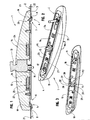
- Figure 1 is a schematic representation in longitudinal section, of a fitting, according to the invention, mounted on a tubular joinery profile.
- Figure 2 is a schematic representation in perspective of the fitting illustrated in Figure 1 illustrating the attachment devices in their inactive position.
- Figure 3 is a representation similar to Figure 2 showing the attachment devices in their active position.
- the present invention relates to the field of fittings more particularly intended to be mounted externally on a joinery, such as an opening frame or a door frame, window or the like .
- the present invention will find a particular interest in the field of lock fittings for sliding leaf.
- the fitting 1 which is the subject of the present invention, comes into application, on the external side 2, on a tubular section 3, corresponding, for example, to the front upright of a sliding door leaf. or window.
- this fitting 1 comprises, at its rear face 4, intended precisely to come to apply to this section 3, means 5 provided for securing it on the latter.
- such fastening means 5 consist of at least one attachment device 6, 7 designed movably, between an inactive position I, as shown in FIG. 2, and an active position A, corresponding to FIGS. 3.
- this attachment device 6, 7 is provided to extend under a hooking flange 8, 9 defined by an opening 10 made in the joinery, in this case the section 3.
- this opening 10 in the joinery is intended to allow the fitting 1 to cooperate with other fitting elements, in particular with locking members, or even in the context of a sliding door or window, with a fitting mounted on the inner side of the sliding leaf.
- locking means 11 are designed to keep the attachment device or devices 6, 7 in their inactive position I, against the action of resilient return means 12.
- these locking means 11 are designed to be released, irreversibly, by a control member 13 which is illustrated in the figures of the attached drawing, as being the key element.
- this control member 13 may borrow another embodiment, knowing that it is necessarily accessible at any of the external faces 14 of the fitting 1.
- an attachment device 6, 7 is in the form of a slider 15, 16 mounted longitudinally at the rear face 4 of the fitting 1.
- This slider 15, 16 has an end 17 in the form of a bolt 18 extending in a substantially offset plane, so as to be salient with respect to the face rear 4 of the fitting 1, to be able to engage under the hooking flange 8, 9 as indicated above.
- the fitting 1 comprises, as fastening means 5, two gripping devices 6, 7 acting in opposition and therefore coming to extend in opposite longitudinal directions at the rear face 4 of FIG. this fitting 1. Being thus able to fit under the hooking flanges 8, 9 that define the opposite ends 19, 20 of the opening 10 in the joinery, these attachment devices 6, 7 ensure perfect fitting of the fitting 1.
- the elastic return means 12 are in the form of a helical spring 24 taking up position in a housing 25 formed accordingly, at the rear face 4 of the fitting 1.
- this housing 25 is further engaged a tongue 27 extending perpendicularly to the rear of a slide 15, 16.
- the coil spring 24 is interposed between one end 26 of the housing 25 and said tongue 27. in such a way as to push the slider 15, 16 into a position corresponding to the active position of the attachment device 6, 7.
- these are constituted, at the end 28 of a slider 15, 16, opposite to that 17 of the bolt 18, by a gripping finger 29, 30 defined able to cooperate with a cam 31 associated with the control member 13.
- this cam 31 is in the form of a hub rotatably mounted on the axis 32 of the key element defining the control member 13.
- this cam 31 is defined so that, in a first angular position P1, it is located on the longitudinal path of the gripping finger 29, 30 and in a second angular position P2 is erased with respect to this trajectory.
- this cam 31 is able to register at the rear of a boss 33 that has, at its end, the latching finger 29, 30 to maintain the shackle 6, 7 in its inactive position I. More particularly, thus coming to register at the rear of this boss 33, the cam 31 retains, through the gripping finger 29, 30, the slide 15, 16 in a retracted position, against the action of the elastic return means 12.
- the blocking means have only a blocking function and not a training function.
- the sliders 15, 16, corresponding to the attachment devices 6, 7 and acting in opposite directions adopt a symmetrical arrangement with respect to the axis of pivoting of the cam 31. More particularly, the gripping fingers 29, 30 of these sliders 15, 16 act diametrically opposite on the cam 31.
- the fitting of the fitting 1 occurs after arming the system. More particularly, it is to bring the attachment devices 6, 7 in their inactive position I. For this, it comes to push the slides 15, 16 in the direction of the central cam 31 against the action of the springs 24
- the cam 31 initially in the second angular position P2 is turned in its first angular position P1 in which it fits behind the boss 33 at the end of the gripping fingers 28, 29 of these slides 15, 16 .
- stiffness of the springs 24 is chosen relatively important to secure the fixing and prevent any risk of disassembly of the hardware from outside a home.
- the first angular position P1 in which the cam 31 is in the path of the gripping fingers 29, 30, more particularly the boss 33 they have at their end may correspond to the rest position of the key element defining the control member 13. In this regard, it qualifies rest position, that in which the key 36 can be removed from the barrel. Also, after unlocking the locking means 11, resulting in the return of the attachment devices 6, 7 in their active position A, the cam 31, being returned to this angular position P1, or in the path of the bosses 33, can prevent the attachment devices 6, 7 to return to their inactive position I, even by acting directly on the slides 15, 16, through the profile 3 of the joinery.
- the blocking means 11 intervene, moreover, as means for maintaining the attachment device or devices 6, 7 in their active position A.
- the present invention responds advantageously to the problem posed.
Landscapes
- Engineering & Computer Science (AREA)
- Mechanical Engineering (AREA)
- Lock And Its Accessories (AREA)
- Joining Of Building Structures In Genera (AREA)
- Closing And Opening Devices For Wings, And Checks For Wings (AREA)
- Massaging Devices (AREA)
- Seal Device For Vehicle (AREA)
- Electrotherapy Devices (AREA)
- Medicines Containing Material From Animals Or Micro-Organisms (AREA)
- Wing Frames And Configurations (AREA)
Claims (10)
- Beschlag, insbesondere zur Verriegelung, umfassend Befestigungsmittel (5) aufliegend an einem röhrenförmigen Profil (3) einer Schreinerei, wie ein Flügel oder ein Blendrahmen eines Fensters, einer Tür oder dergleichen, dadurch gekennzeichnet, daß die besagten Befestigungsmittel (5) aus wenigstens einer Kupplungsvorrichtung (6, 7) bestehen, die beweglich zwischen einer inaktiven Position (I) und einer aktiven Position (A) vorgesehen ist, in welcher sie vorgesehen ist, um sich unter einem Kupplungsrand (8, 9) zu erstrecken, den eine Öffnung (10) bildet, die in der Schreinerei vorgesehen ist, wobei der besagte Beschlag (1) in Kombination ein Antriebsorgan (13) wie ein Schlüsselelement umfaßt, vorgesehen, um auf nicht umkehrbare Art und Weise die Entriegelung der Sperrmittel (11) zu sichern, die konzipiert sind, um die besagte Vorrichtung (6, 7) in ihrer inaktiven Position (I) gegen die Wirkung der elastischen Rückstellmittel (12) zu halten.
- Beschlag nach irgendeinem der vorgehenden Ansprüche, dadurch gekennzeichnet, daß er zwei Kupplungsvorrichtungen (6, 7) umfaßt, die entgegengesetzt wirken und sich nach einer entgegengesetzten Längsrichtung im Bereich der hinteren Seite (4) des Beschlages (1) erstrecken.
- Beschlag nach Anspruch 1 oder 2, dadurch gekennzeichnet, daß eine Kupplungsvorrichtung (6, 7) als ein Schieber (15, 16) ausgestaltet ist, der beweglich in Längsrichtung im Bereich der hinteren Seite (4) von Beschlag 1 montiert ist, vorgesehen, um auf der Schreinerei aufzuliegen, wobei dieser Schieber (15, 16) ein Ende (15) umfaßt, das eine Riegelartige Form (18) hat und geeignet vorgesehen ist, um in aktiver Position (A) der besagten Kupplungsvorrichtung (6, 7) unter einem Kupplungsrand (8, 9) einzugreifen.
- Beschlag nach Anspruch 3, dadurch gekennzeichnet, daß der Riegel (18), einerseits, hinsichtlich der Ebene des Schiebers (15, 16) verschoben ist, um hinsichtlich der hinteren Seite (4) des Beschlages (1) vorzuspringen, und, andererseits, um einen spitzen Winkel (21) hinsichtlich dieser hinteren Seite (4) zu bilden.
- Beschlag nach Anspruch 3 oder 4, dadurch gekennzeichnet, daß die Sperrmittel (11) am Ende (28) eines Schiebers (15, 16), das jenem (17) entgegengesetzt ist, das mit dem Riegel (18) ausgestattet ist, durch einen Kupplungsfinger (29, 30) gebildet sind, der geeignet gebildet ist, um mit einem Nocken (31) zusammenzuwirken, der mit dem Antriebsorgan (13) verbunden ist.
- Beschlag nach Anspruch 5, dadurch gekennzeichnet, daß der Nocken (31) dazu gebildet ist, um, in einer ersten Winkelstellung (P1), sich auf der Längsflugbahn des Kupplungsfingers (29, 30) zu befinden, und, in einer zweiten Winkelstellung (P2), sich hinsichtlich dieser Flugbahn zurückzuziehen, wobei in der besagten ersten Winkelstellung (P1) der besagte Nocken (31) fähig vorgesehen sei, um am hinteren Teil eines Buckels (33) aufgenommen zu werden, den der besagte Kupplungsfinger (29, 30) an seinem Ende umfaßt, um die Kupplungsvorrichtung (6, 7) in ihrer inaktiven Position (I) zu halten.
- Beschlag nach irgendeinem Anspruch 3 bis 6, dadurch gekennzeichnet, daß die elastischen Rückstellmittel (12) durch eine Spiralfeder (24) gebildet sind, die sich in einer Ausnehmung (25) positioniert, die im Bereich der hinteren Seite (4) des Beschlages (1) vorgesehen ist, wobei die besagte Feder (24) mit einem Zünglein (27) zusammenwirkt, das mit dem Schieber (15, 16) fest verbunden ist, der sich im Innern der Ausnehmung (25) erstreckt.
- Beschlag nach irgendeinem der Ansprüche 3 bis 7, dadurch gekennzeichnet, daß die Schieber (15, 16), die den beiden, entgegengesetzt wirkenden Kupplungsvorrichtungen (6, 7) entsprechen, eine symmetrische Anordnung hinsichtlich der Schwenkachse des Nockens (31) einnehmen, und ihren entsprechenden Kupplungsfinger (29, 30) umfassen, die auf diametral entgegengesetzte Art und Weise auf diesen Nocken (31) wirken.
- Beschlag nach irgendeinem der Ansprüche 3 bis 8, dadurch gekennzeichnet, daß der oder die Schieber 15, 16 zwischen den seitlichen Führungsrändern (34, 35) im Bereich der hinteren Seite (4) des Beschlages (1) aufgenommen werden können.
- Beschlag nach irgendeinem der vorgehenden Ansprüche, dadurch gekennzeichnet, daß die Sperrmittel (11) noch Mittel bilden, um die Kupplungsvorrichtung oder -vorrichtungen (6, 7) in ihrer aktiven Position (A) zu halten.
Applications Claiming Priority (2)
| Application Number | Priority Date | Filing Date | Title |
|---|---|---|---|
| FR0450107A FR2865229B1 (fr) | 2004-01-21 | 2004-01-21 | Ferrure notamment de verrouillage |
| FR0450107 | 2004-01-21 |
Publications (2)
| Publication Number | Publication Date |
|---|---|
| EP1557511A1 EP1557511A1 (de) | 2005-07-27 |
| EP1557511B1 true EP1557511B1 (de) | 2007-06-27 |
Family
ID=34630690
Family Applications (1)
| Application Number | Title | Priority Date | Filing Date |
|---|---|---|---|
| EP05300038A Expired - Lifetime EP1557511B1 (de) | 2004-01-21 | 2005-01-17 | Verriegelungsbeschlag |
Country Status (5)
| Country | Link |
|---|---|
| EP (1) | EP1557511B1 (de) |
| AT (1) | ATE365846T1 (de) |
| DE (1) | DE602005001451D1 (de) |
| ES (1) | ES2288733T3 (de) |
| FR (1) | FR2865229B1 (de) |
Cited By (1)
| Publication number | Priority date | Publication date | Assignee | Title |
|---|---|---|---|---|
| EP3307973B1 (de) | 2015-07-28 | 2020-09-02 | MACO Technologie GmbH | Verschluss für ein fenster, eine tür oder dergleichen |
Families Citing this family (2)
| Publication number | Priority date | Publication date | Assignee | Title |
|---|---|---|---|---|
| FR2888867B1 (fr) * | 2005-07-19 | 2007-09-07 | Ferco Int Usine Ferrures | Ferrure notamment de verrouillage |
| DE102015112261A1 (de) * | 2015-07-28 | 2017-02-02 | Maco Technologie Gmbh | Verschluss für ein Fenster, eine Tür oder dergleichen |
Family Cites Families (4)
| Publication number | Priority date | Publication date | Assignee | Title |
|---|---|---|---|---|
| GB183573A (en) * | 1921-04-26 | 1922-07-26 | Charles Herbert Smith | Improvements in locks and bolts for securing van and other doors |
| KR870001626Y1 (ko) * | 1985-05-24 | 1987-04-30 | 주식회사금성사 | 전자레인지의 도어 개폐장치 |
| FR2761719B1 (fr) * | 1997-04-03 | 1999-06-18 | Ferco Int Usine Ferrures | Ferrure de verrouillage pour ouvrant coulissant |
| FR2788547B3 (fr) * | 1999-01-19 | 2000-12-22 | Mecelec Ind | Serrure pour coffret hors sol et coffret hors sol de protection d'un dispositif de raccordement equipe d'une telle serrure |
-
2004
- 2004-01-21 FR FR0450107A patent/FR2865229B1/fr not_active Expired - Fee Related
-
2005
- 2005-01-17 EP EP05300038A patent/EP1557511B1/de not_active Expired - Lifetime
- 2005-01-17 DE DE602005001451T patent/DE602005001451D1/de not_active Expired - Lifetime
- 2005-01-17 AT AT05300038T patent/ATE365846T1/de not_active IP Right Cessation
- 2005-01-17 ES ES05300038T patent/ES2288733T3/es not_active Expired - Lifetime
Cited By (2)
| Publication number | Priority date | Publication date | Assignee | Title |
|---|---|---|---|---|
| EP3307973B1 (de) | 2015-07-28 | 2020-09-02 | MACO Technologie GmbH | Verschluss für ein fenster, eine tür oder dergleichen |
| EP3502386B1 (de) | 2015-07-28 | 2020-12-30 | MACO Technologie GmbH | Verschluss für ein fenster, eine tür oder dergleichen |
Also Published As
| Publication number | Publication date |
|---|---|
| FR2865229B1 (fr) | 2006-04-21 |
| ES2288733T3 (es) | 2008-01-16 |
| ATE365846T1 (de) | 2007-07-15 |
| DE602005001451D1 (de) | 2007-08-09 |
| FR2865229A1 (fr) | 2005-07-22 |
| EP1557511A1 (de) | 2005-07-27 |
Similar Documents
| Publication | Publication Date | Title |
|---|---|---|
| EP0869241B1 (de) | Schiebetürverschluss | |
| EP2317042B1 (de) | Schrank, der eine Vitrine bildet, mit Verriegelung mindestens einer Schiebescheibe | |
| FR3087218A1 (fr) | Ensemble de poignee pour ouvrants de type fenetre ou porte | |
| EP1927717A1 (de) | Führungskulisse für ein Verschluss-und/oder Verdunklungselement | |
| WO2006123075A1 (fr) | Dispositif de fixation d'une ventouse ou d'une contrepiaque de serrure electromagnetique dans un profile | |
| FR2865229A1 (fr) | Ferrure notamment de verrouillage | |
| EP1336716B1 (de) | Befestigungsvorrichtung für einen Verschlussdeckel auf einem Rolladenkasten | |
| EP2415954A1 (de) | Einsatzbeschlag, der einen Befestigungsflansch umfasst | |
| EP0892133B1 (de) | Verriegelungsbeschlag für Schiebeflügel und Einbruchssicherung für einen solchen Beschlag | |
| FR3001754A1 (fr) | Dispositif de blocage d'un panneau mobile en translation et dispositif d'occultation comportant un tel dispositif. | |
| EP1746224A1 (de) | Verriegelungsbeschlag | |
| EP0246989B1 (de) | Sicherheitstür, insbesondere für Kästen, Fächer und Geldschränke | |
| FR3022939A1 (fr) | Dispositif d'ouverture et de fermeture d'un article notamment de maroquinerie et article comportant un tel dispositif | |
| CH693218A5 (fr) | Ferrure de verrouillage d'ouvrant dotée pour sa fixation de moyens d'appui intérieur et extérieur décalés et ouvrant équipé d'un telle ferrure. | |
| EP0070576B2 (de) | Treibstangengetriebe für Tür, Fenster o.dgl. | |
| EP0997598B1 (de) | Schraubenführungsvorrichtung für Treibstange oder Treibstangenschloss | |
| FR2888602A1 (fr) | Serrure de porte | |
| EP1475497A1 (de) | Sperriegel für Tür- oder Fensterflügel | |
| EP2112303B1 (de) | Vorrichtung zur Verhinderung von Fehlbedienung und Treibstangenverriegelungsbeschlag für eine Schiebetür | |
| EP1088957B1 (de) | Treibstangenverschluss für Rahmen von Türen oder Fenstern | |
| FR2680825A1 (fr) | Ferrure de verrouillage pour porte, fenetre ou analogue. | |
| EP1241307B1 (de) | Feststeller für Tür, Fenster dgl. mit treibstangenverschlussartigen Beschlag | |
| EP2386706A1 (de) | Verrieglungsvorrichtung für halbfesten Fensterflügel | |
| EP4050182B1 (de) | Vorrichtung zur steuerung eines verriegelungs-/entriegelungsmechanismus eines öffnungsflügels | |
| FR2865231A1 (fr) | Ferrure de verrouillage pour ouvrant coulissant |
Legal Events
| Date | Code | Title | Description |
|---|---|---|---|
| PUAI | Public reference made under article 153(3) epc to a published international application that has entered the european phase |
Free format text: ORIGINAL CODE: 0009012 |
|
| AK | Designated contracting states |
Kind code of ref document: A1 Designated state(s): AT BE BG CH CY CZ DE DK EE ES FI FR GB GR HU IE IS IT LI LT LU MC NL PL PT RO SE SI SK TR |
|
| AX | Request for extension of the european patent |
Extension state: AL BA HR LV MK YU |
|
| 17P | Request for examination filed |
Effective date: 20050702 |
|
| AKX | Designation fees paid |
Designated state(s): AT BE BG CH CY CZ DE DK EE ES FI FR GB GR HU IE IS IT LI LT LU MC NL PL PT RO SE SI SK TR |
|
| GRAC | Information related to communication of intention to grant a patent modified |
Free format text: ORIGINAL CODE: EPIDOSCIGR1 |
|
| GRAP | Despatch of communication of intention to grant a patent |
Free format text: ORIGINAL CODE: EPIDOSNIGR1 |
|
| GRAS | Grant fee paid |
Free format text: ORIGINAL CODE: EPIDOSNIGR3 |
|
| GRAA | (expected) grant |
Free format text: ORIGINAL CODE: 0009210 |
|
| AK | Designated contracting states |
Kind code of ref document: B1 Designated state(s): AT BE BG CH CY CZ DE DK EE ES FI FR GB GR HU IE IS IT LI LT LU MC NL PL PT RO SE SI SK TR |
|
| REG | Reference to a national code |
Ref country code: GB Ref legal event code: FG4D Free format text: NOT ENGLISH |
|
| REG | Reference to a national code |
Ref country code: CH Ref legal event code: EP |
|
| REG | Reference to a national code |
Ref country code: IE Ref legal event code: FG4D Free format text: LANGUAGE OF EP DOCUMENT: FRENCH |
|
| REF | Corresponds to: |
Ref document number: 602005001451 Country of ref document: DE Date of ref document: 20070809 Kind code of ref document: P |
|
| PG25 | Lapsed in a contracting state [announced via postgrant information from national office to epo] |
Ref country code: SE Free format text: LAPSE BECAUSE OF FAILURE TO SUBMIT A TRANSLATION OF THE DESCRIPTION OR TO PAY THE FEE WITHIN THE PRESCRIBED TIME-LIMIT Effective date: 20070927 |
|
| PG25 | Lapsed in a contracting state [announced via postgrant information from national office to epo] |
Ref country code: PL Free format text: LAPSE BECAUSE OF FAILURE TO SUBMIT A TRANSLATION OF THE DESCRIPTION OR TO PAY THE FEE WITHIN THE PRESCRIBED TIME-LIMIT Effective date: 20070627 Ref country code: AT Free format text: LAPSE BECAUSE OF FAILURE TO SUBMIT A TRANSLATION OF THE DESCRIPTION OR TO PAY THE FEE WITHIN THE PRESCRIBED TIME-LIMIT Effective date: 20070627 |
|
| NLV1 | Nl: lapsed or annulled due to failure to fulfill the requirements of art. 29p and 29m of the patents act | ||
| REG | Reference to a national code |
Ref country code: ES Ref legal event code: FG2A Ref document number: 2288733 Country of ref document: ES Kind code of ref document: T3 |
|
| GBV | Gb: ep patent (uk) treated as always having been void in accordance with gb section 77(7)/1977 [no translation filed] |
Effective date: 20070627 |
|
| REG | Reference to a national code |
Ref country code: IE Ref legal event code: FD4D |
|
| PG25 | Lapsed in a contracting state [announced via postgrant information from national office to epo] |
Ref country code: NL Free format text: LAPSE BECAUSE OF FAILURE TO SUBMIT A TRANSLATION OF THE DESCRIPTION OR TO PAY THE FEE WITHIN THE PRESCRIBED TIME-LIMIT Effective date: 20070627 Ref country code: IS Free format text: LAPSE BECAUSE OF FAILURE TO SUBMIT A TRANSLATION OF THE DESCRIPTION OR TO PAY THE FEE WITHIN THE PRESCRIBED TIME-LIMIT Effective date: 20071027 Ref country code: CZ Free format text: LAPSE BECAUSE OF FAILURE TO SUBMIT A TRANSLATION OF THE DESCRIPTION OR TO PAY THE FEE WITHIN THE PRESCRIBED TIME-LIMIT Effective date: 20070627 Ref country code: LT Free format text: LAPSE BECAUSE OF FAILURE TO SUBMIT A TRANSLATION OF THE DESCRIPTION OR TO PAY THE FEE WITHIN THE PRESCRIBED TIME-LIMIT Effective date: 20070627 Ref country code: IE Free format text: LAPSE BECAUSE OF FAILURE TO SUBMIT A TRANSLATION OF THE DESCRIPTION OR TO PAY THE FEE WITHIN THE PRESCRIBED TIME-LIMIT Effective date: 20070627 Ref country code: SI Free format text: LAPSE BECAUSE OF FAILURE TO SUBMIT A TRANSLATION OF THE DESCRIPTION OR TO PAY THE FEE WITHIN THE PRESCRIBED TIME-LIMIT Effective date: 20070627 Ref country code: BG Free format text: LAPSE BECAUSE OF FAILURE TO SUBMIT A TRANSLATION OF THE DESCRIPTION OR TO PAY THE FEE WITHIN THE PRESCRIBED TIME-LIMIT Effective date: 20070927 Ref country code: PT Free format text: LAPSE BECAUSE OF FAILURE TO SUBMIT A TRANSLATION OF THE DESCRIPTION OR TO PAY THE FEE WITHIN THE PRESCRIBED TIME-LIMIT Effective date: 20071127 |
|
| PG25 | Lapsed in a contracting state [announced via postgrant information from national office to epo] |
Ref country code: SK Free format text: LAPSE BECAUSE OF FAILURE TO SUBMIT A TRANSLATION OF THE DESCRIPTION OR TO PAY THE FEE WITHIN THE PRESCRIBED TIME-LIMIT Effective date: 20070627 |
|
| PG25 | Lapsed in a contracting state [announced via postgrant information from national office to epo] |
Ref country code: DK Free format text: LAPSE BECAUSE OF FAILURE TO SUBMIT A TRANSLATION OF THE DESCRIPTION OR TO PAY THE FEE WITHIN THE PRESCRIBED TIME-LIMIT Effective date: 20070627 Ref country code: DE Free format text: LAPSE BECAUSE OF FAILURE TO SUBMIT A TRANSLATION OF THE DESCRIPTION OR TO PAY THE FEE WITHIN THE PRESCRIBED TIME-LIMIT Effective date: 20070928 Ref country code: GR Free format text: LAPSE BECAUSE OF FAILURE TO SUBMIT A TRANSLATION OF THE DESCRIPTION OR TO PAY THE FEE WITHIN THE PRESCRIBED TIME-LIMIT Effective date: 20070928 |
|
| PLBE | No opposition filed within time limit |
Free format text: ORIGINAL CODE: 0009261 |
|
| STAA | Information on the status of an ep patent application or granted ep patent |
Free format text: STATUS: NO OPPOSITION FILED WITHIN TIME LIMIT |
|
| PG25 | Lapsed in a contracting state [announced via postgrant information from national office to epo] |
Ref country code: GB Free format text: LAPSE BECAUSE OF FAILURE TO SUBMIT A TRANSLATION OF THE DESCRIPTION OR TO PAY THE FEE WITHIN THE PRESCRIBED TIME-LIMIT Effective date: 20070627 Ref country code: RO Free format text: LAPSE BECAUSE OF FAILURE TO SUBMIT A TRANSLATION OF THE DESCRIPTION OR TO PAY THE FEE WITHIN THE PRESCRIBED TIME-LIMIT Effective date: 20070627 |
|
| 26N | No opposition filed |
Effective date: 20080328 |
|
| BERE | Be: lapsed |
Owner name: FERCO INTERNATIONAL FERRURES ET SERRURES DE BATIM Effective date: 20080131 |
|
| PG25 | Lapsed in a contracting state [announced via postgrant information from national office to epo] |
Ref country code: MC Free format text: LAPSE BECAUSE OF NON-PAYMENT OF DUE FEES Effective date: 20080131 |
|
| PG25 | Lapsed in a contracting state [announced via postgrant information from national office to epo] |
Ref country code: EE Free format text: LAPSE BECAUSE OF FAILURE TO SUBMIT A TRANSLATION OF THE DESCRIPTION OR TO PAY THE FEE WITHIN THE PRESCRIBED TIME-LIMIT Effective date: 20070627 |
|
| PG25 | Lapsed in a contracting state [announced via postgrant information from national office to epo] |
Ref country code: FI Free format text: LAPSE BECAUSE OF FAILURE TO SUBMIT A TRANSLATION OF THE DESCRIPTION OR TO PAY THE FEE WITHIN THE PRESCRIBED TIME-LIMIT Effective date: 20070627 Ref country code: BE Free format text: LAPSE BECAUSE OF NON-PAYMENT OF DUE FEES Effective date: 20080131 |
|
| PGFP | Annual fee paid to national office [announced via postgrant information from national office to epo] |
Ref country code: ES Payment date: 20090122 Year of fee payment: 5 |
|
| PG25 | Lapsed in a contracting state [announced via postgrant information from national office to epo] |
Ref country code: CY Free format text: LAPSE BECAUSE OF FAILURE TO SUBMIT A TRANSLATION OF THE DESCRIPTION OR TO PAY THE FEE WITHIN THE PRESCRIBED TIME-LIMIT Effective date: 20070627 |
|
| REG | Reference to a national code |
Ref country code: CH Ref legal event code: PL |
|
| PG25 | Lapsed in a contracting state [announced via postgrant information from national office to epo] |
Ref country code: CH Free format text: LAPSE BECAUSE OF NON-PAYMENT OF DUE FEES Effective date: 20090131 Ref country code: LI Free format text: LAPSE BECAUSE OF NON-PAYMENT OF DUE FEES Effective date: 20090131 |
|
| PG25 | Lapsed in a contracting state [announced via postgrant information from national office to epo] |
Ref country code: LU Free format text: LAPSE BECAUSE OF NON-PAYMENT OF DUE FEES Effective date: 20080117 Ref country code: HU Free format text: LAPSE BECAUSE OF FAILURE TO SUBMIT A TRANSLATION OF THE DESCRIPTION OR TO PAY THE FEE WITHIN THE PRESCRIBED TIME-LIMIT Effective date: 20071228 |
|
| PG25 | Lapsed in a contracting state [announced via postgrant information from national office to epo] |
Ref country code: TR Free format text: LAPSE BECAUSE OF FAILURE TO SUBMIT A TRANSLATION OF THE DESCRIPTION OR TO PAY THE FEE WITHIN THE PRESCRIBED TIME-LIMIT Effective date: 20070627 |
|
| REG | Reference to a national code |
Ref country code: ES Ref legal event code: FD2A Effective date: 20110225 |
|
| PGFP | Annual fee paid to national office [announced via postgrant information from national office to epo] |
Ref country code: FR Payment date: 20110202 Year of fee payment: 7 |
|
| PG25 | Lapsed in a contracting state [announced via postgrant information from national office to epo] |
Ref country code: ES Free format text: LAPSE BECAUSE OF NON-PAYMENT OF DUE FEES Effective date: 20110224 |
|
| PG25 | Lapsed in a contracting state [announced via postgrant information from national office to epo] |
Ref country code: ES Free format text: LAPSE BECAUSE OF NON-PAYMENT OF DUE FEES Effective date: 20100118 |
|
| REG | Reference to a national code |
Ref country code: FR Ref legal event code: ST Effective date: 20120928 |
|
| PG25 | Lapsed in a contracting state [announced via postgrant information from national office to epo] |
Ref country code: FR Free format text: LAPSE BECAUSE OF NON-PAYMENT OF DUE FEES Effective date: 20120131 |
|
| PGFP | Annual fee paid to national office [announced via postgrant information from national office to epo] |
Ref country code: IT Payment date: 20210121 Year of fee payment: 17 |
|
| PG25 | Lapsed in a contracting state [announced via postgrant information from national office to epo] |
Ref country code: IT Free format text: LAPSE BECAUSE OF NON-PAYMENT OF DUE FEES Effective date: 20220117 |